Note: Descriptions are shown in the official language in which they were submitted.
CA 03194070 2023-03-06
WO 2022/056044
PCT/US2021/049533
METHODS AND APPARATUS FOR METAL STRUCTURE FABRICATION
FIELD OF INVENTION
The invention relates generally to welded components and metallurgy, and,
particularly
the pre- and post-heat treatment to welding of pressurized containers.
BACKGROUND OF ART
Storing and transporting various materials, such as gas and liquids, by road,
rail and sea
under pressure and/or refrigeration can present problems due to weight,
potential failure, and/or
cost of the pressure vessel systems. Materials used in the manufacture of such
vessels are heavy
and are prone to corrosion and weakening. The vessels can also be limited to
usage at near
ambient storage temperatures as the potential danger for brittle/ductile
failure exists due to Joule
Thompson effects caused by decompression.
Manufacturing and building these large structures, especially pressure
vessels, provides
various challenges during assembly. For example, welding portions of the walls
or panels of the
structures require significant resources, including, but not limited to,
workers, time, energy, non-
structural materials, and safety equipment. This is because the welds require
certain steps be
taken to provide a sound structure, e.g., pressure vessels used in the oil
industry.
Many industries use pressure vessels for transporting, transferring and/or
storing various
materials under high pressure, e.g., gas or liquid. Given the applications of
pressure vessels,
welds undergo considerable quality inspections, including X-rays and
certifications. If the weld
fails the inspections, then the weld is removed and replaced with a patch.
Given high demands
for such vessels in these industries, a failed weld is costly. Thus, material
preparation and proper
welding techniques are necessary to avoid lost profits and wasted resources.
Material preparation can include preheating all or portions of the vessel
walls or
components of the vessel walls that are to be welded together. Such
preparation requires proper
placement of heating components and insulating components because the weld
placements are
important for creating welds that meet manufacturer's design specifications
and pass inspection.
In currently practiced methods of manufacturing such vessels, excessive time
must be taken for
allowing materials to cool after heating to allow personnel to further
manipulate the metals. In
other situations, time is lost in pretreating metals with heat in preparation
for welding. What is
needed to address this and other issues is a temporary, mobile apparatus for
weld preparation
and completion to address loss of resources, such as loss of time, space, and
fabrication
production due to the impossibility of workers beginning or continuing work on
the subject
materials due to high temperatures. These needs are addressed by the present
invention.
1
CA 03194070 2023-03-06
WO 2022/056044
PCT/US2021/049533
SUMMARY
Provided herein are embodiments of the invention providing a temporary and
mobile
convection apparatus and methods related weld projects requiring weld
preparation and/or
completion.
In some embodiments, an apparatus and methods are provided for pre-heating
substrate
materials for joining portions of a vessel body, and/or mechanical lining, for
mechanical strength
of a welded joint portion, and giving options for shape of the weld joint
portion and position.
Certain embodiments of the invention provide an apparatus and methods for pre-
heating
substrate materials and maintaining the pre-heat temperatures throughout the
welding of the
substrate materials. Embodiments of the invention provide an apparatus and
methods for
reducing resources required for achieving and maintaining pre-heated
temperatures for the
welding.
In some embodiments, a temporary, mobile convection apparatus is provided,
wherein
convection occurs internal to a space created by the convection apparatus. In
further
embodiments, panels (barrier or walls) form a convection section of the
convection apparatus.
In one embodiment, a convection apparatus of the invention can have a
manifold, wherein a pipe
or pipes of the manifold are housed within the internal space of the
convection apparatus as the
apparatus is temporarily affixed to or abutted with the substrate materials
being treated and/or
welded. Some embodiments of the invention provide terminus throttles for
aiding in pre-heating,
maintaining a desired pre-heated temperature, or cooling of substrate
materials for the weld
exposed to an interior area of the convection section of the convection
apparatus. Various
embodiments provide an extension to the manifold for purposes of attachment to
heating and/or
cooling equipment. Additional embodiments include heating and/or cooling
equipment for
attachment to the manifold of the convection apparatus. Some embodiments of
the invention
have one or more manifolds coated with a thermal barrier. In yet other
embodiments, the
materials, lengths and dimensions of the manifold components can be varied to
address the
requirements of the job. In some embodiments, there can be one, two or more
manifolds
provided as part of the convection apparatus.
Certain embodiments of the invention provide a convection apparatus for
placement
internally or externally to a pressure vessel or other equipment. In certain
embodiments,
insulation and heating elements are provided for pre-heating and maintaining
the achieved
temperature of a substrate material for welding. In various embodiments, the
heating elements
with insulation can be placed external or internal to the vessel, and can be
positioned to form a
2
CA 03194070 2023-03-06
WO 2022/056044
PCT/US2021/049533
heated band and heating gradient bands in relevant locations to a weld site of
the substrate
materials.
The present invention provides embodiments of an apparatus and methods for
fabrication
or repair of pressure vessels and other products requiring welds.
Additional features, advantages, and embodiments of the invention may be set
forth or
apparent from consideration of the following detailed description, drawings,
and claims.
Moreover, it is to be understood that both the foregoing summary of the
invention and the
following detailed description are exemplary and intended to provide further
explanation without
limiting the scope of the invention as claimed.
BRIEF DESCRIPTION OF THE DRAWINGS
The accompanying drawings, which are included to provide a further
understanding of
the invention and are incorporated in and constitute a part of this
specification, illustrate
preferred embodiments of the invention and together with the detailed
description serve to
explain the principles of the invention. In the drawings:
Fig. 1 is a side view of various embodiments of the present invention
assembled for
purposes of one type of pre-heat of substrate materials of a weld.
Fig. 2 is (2a) a side view of a convection apparatus constructed according to
certain
principles of the invention, and (2b) a side view of an apparatus without a
convection aspect as
known in the prior art.
Fig. 3 is a side view of a manifold system according to certain principles of
the invention.
Figs. 4(a) and 4(b) depict heating elements positioned around a piece of steel
wrapped in
portions of ceramic fiber.
Figs. 5(a) and 5(b) depict the installation of ceramic fiber inside of steel
used in Trial 1.
The ceramic fiber was supported and held in position using wire mesh.
Figs. 6(a) and 6(b) depict the installation of ceramic fiber inside of steel
used in Trial 1.
The ceramic fiber was supported and held in position using wire mesh.
Figs 7(a) and 7(b) depict the installation of ceramic fiber inside of steel
used in Trial 2
prior to the installation of internal panels. The ceramic fiber was supported
and held in position
using wire mesh.
Figs. 8(a) and 8(b) depict internal panels made in accordance with the
disclosure
contained herein positioned inside of a piece of steel used for Trial 2
Figs. 9(a) and 9(b) depict a piece of steel covered in panels in accordance
with
embodiments of the present invention and including a blower positioned on the
panels
3
CA 03194070 2023-03-06
WO 2022/056044
PCT/US2021/049533
Fig. 10 is a graph showing temperature as a function of time produced as a
result of the
test in Trial 1.
Fig. 11 is a graph showing temperature as a function of time produced as a
result of the
test in Trial 2.
Fig. 12 is a graph showing the data produced via Trial 3.
Fig. 13 is a graph comparing the results of Trials 1-3.
Figs. 14(a) and 14(b) depict an embodiment containing an angled portion of a
manifold
inlet.
Figs. 15(a) and 15(b) depict a slidable end vent positioned on a panel in
accordance with
the disclosure.
Fig. 16(a) depicts a spring-loaded end vent for a panel made in accordance
with the
disclosure.
Fig. 16(b) shows an isometric view of a valve flap for a spring-loaded end
vent made in
accordance with the disclosure.
Fig. 16c shows a top view of a valve flap made for use in conjunction with a
spring-
loaded end vent.
Fig. 16d shows a bracket cutout for a spring-loaded valve flap.
DETAILED DESCRIPTION OF THE PREFERRED EMBODIMENTS
Various embodiments of the present invention are illustrated and/or explained
herein.
Fig. 1 provides an embodiment of the invention. As shown, a temporary, mobile
convection apparatus is provided in relation to a substrate material, e.g.,
sections of pipes 101.
A weld site or area 120 is provided, showing where sections of pipes 101 are
to be joined via a
weld at 120. Pipe 101 may comprise a convention section that is positioned on
either side of the
weld site or area 120. As described herein, a convection section is positioned
in proximity to
weld site or area 120 for multiple purposes. One purpose can be to pre-heat
the substrate material
of pipes 101 to be welded together. As will be appreciated by those in the
art, the requirements
of any job will determine whether one or more convection sections are
required. For example,
small jobs may only require or provide for use of one convection section in
close proximity to
weld site or area 120. By way of example, Fig. 1 illustrates the use of two
convection sections,
with one on each side of weld site or area 120 for pre-heating the substrate
material of pipes 101
to be welded together. As shown, convection sections can be configured to
encompass a portion
or the entire circumference (360 degrees) of pipes 101 on each side of weld
site or area 120.
4
CA 03194070 2023-03-06
WO 2022/056044
PCT/US2021/049533
Heat is applied into convection sections or boxes 110 to control the pre-heat
weld temperature.
Conversely, convection sections or boxes 110 could be used for passing cooled
air through the
internal space of convection sections or boxes 110 to control the weld
interpass temperature.
Certain aspects of the embodiments shown in Fig. 1 are discussed and described
in more detail
herein. As should be appreciated by the skilled artisan, weld sites or areas
as described herein
are not covered by any apparatus described herein during the pre-heating,
maintaining of pre-
heating temperatures for welding, or during post-weld cooling.
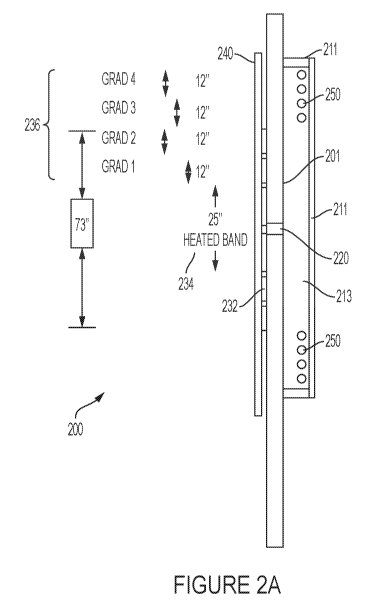
Fig. 2a shows a side view of a vessel wall 201 with an internal convection
apparatus.
The convection apparatus in this embodiment is a convection section, wherein
convection
section 200 comprises a panel 211 (e.g., barrier or wall). The convection
apparatus is a
temporary, mobile convection apparatus forming an internal space or internal
convection space
213 to provide internal convection of heated or cooled air as provided herein.
Unless otherwise
provided herein, the term "internal convection" refers to convection occurring
within the internal
space 213 created by the convection apparatus being affixed to or abutted
against, around and/or
on the substrate materials to be welded, being welded, or cooling from being
welded, such as the
vessel wall 201. The convection section provides a panel 211 (barrier or wall)
to form a desired
shape of a convection section. The convection section can be comprised of
multiple panels 211,
wherein the convection apparatus is mobile for temporary construction,
placement, and removal.
The panels 211 of the convection section 210 can be manufactured with low
grade aluminum or
other materials such as steel, as will be appreciated by those in the field.
The panels 211 of the
convection section 210 can have a high temperature coating. The high
temperature coating is
designed to contain the heat within the convection box and limit heat loss
through the panels 211
of the convection section 210. As an example, the coating is a lightweight,
high performance,
high temperature thermal insulating barrier coating. High temperature coating
can also comprise
an insulating material like lightweight refractory. Desirable characteristics
of the coatings used
in the present invention can include: 1) a shock cool from 1000F to 77F; 2)
direct flame
resistance of 15 minutes at 2000F; 3) thermal lag of 1,200F temperature drop
after 20 minutes
on a 15mil coating in freely circulating air; 4) maximum temperature of 210F
through coating
after 60 minutes exposure to 300F heat source; 5) maximum temperature of 535F
after 60
minutes exposure to 1000F heat source; and 6) a thermal conductivity of KC at
600 F ¨ 1.8
BTU/hr/ft., 2 deg F/in and KC at 900 F ¨ 2.2 BTU/hr/ft., 2/deg F/in. One
example of such
coating is the PT-209C Caliente High Temperature Thermal Lag.
Certain embodiments can also provide an external heating system. The heating
system
can be adapted to be positioned on a side of vessel wall 201 opposite the
internal convection box
5
CA 03194070 2023-03-06
WO 2022/056044
PCT/US2021/049533
210. The external heating system can comprise one or more external heating
components or
heating elements 232. The heating system is positioned in a manner to create
required heated
bands of various temperature gradients over a required area of the specific
product being
fabricated. By way of example, through the use of convection section, the
heating elements 232
in the heated band's 234 width will increase by at least 67% over that of
other methods, and the
heating elements 232 in the gradient band 236 widths will decrease by about
40%. In some
embodiments, the convention section can be structured as a box surrounding the
portion of the
vessel wall to be heated, and may be referred to as a convection box. However,
the shape of the
convection section is not particularly limited and one of skill in the art
would envisage how to
modify the shape of the convection section to heat and cool the product (i.e.,
substrate) being
fabricated and/or welded. The heating elements 232 in the gradient bands 236
can be used in
series thereby greatly reducing the power requirements and costs of the
embodiments of the
present invention compared to prior art devices. One of skill in the art would
immediately
envisage the types of heating elements that could be used to heat the
substrate and the convection
section. The heating elements can be flexible ceramic pads or electrical
resistance heating
elements and the like. These heating elements can be sized to accord with any
given weld project,
and can be, for example, 80 volt, 45 amp, 3.6KW heating elements. As seen in
Fig. 2a and by
way of example, gradient bands 236 are utilized, wherein the outer two
gradient bands, e.g.,
gradient bands 3 and 4 (GRAD 3 and GRAD 4), achieve temperature control with
use of external
insulation 240 and through heat from the internal space 213 of convection
section. The internal
convection section reduces the external heater requirements by over 30%
without impacting the
quality of the heat treatment.
Also provided is external insulation 240 positioned on a side opposite the
internal space
213 of convection section. The external insulation 240 is also positioned to
insulate the external
heating system, wherein the external heating system is between the external
insulation 240 and
vessel wall 201 sections to be welded. The external insulation 240 is adapted
to cover the
external heaters 232, including extending beyond the ends of the external
heaters 232 to varying
lengths as required by the convection section set up. Length and size of the
external insulation
240 will be determined based on the width of the heated band 234 and gradient
bands 236. The
choice of external insulation 240 can be made based on the size, cost and
requirements of the
fabrication job to be performed. By way of example, welding blankets can be
used to direct the
heat into the metal being prepared for a weld. The external insulation 240
material can be
attached or connected to each other via heavy insulated fiberglass heating
tapes as necessary
and/or affixed to vessel wall 201.
6
CA 03194070 2023-03-06
WO 2022/056044
PCT/US2021/049533
Illustrated in Fig. 2b is a known prior art method of pre-heating a substrate
material, e.g.,
vessel wall 201. As noted, heated band 234 is much narrower than the heated
band of an
embodiment of the invention (e.g., shown in Fig. 2a), which results in wasted
resources such as
electricity and work time for placement of external heater system. This
problem is overcome by
use of the convection section of Fig. 2a, which requires less external heater
elements 232. In
Fig. 2b, external insulation 240 is positioned to each side of a substrate
material to preheat for
welding, e.g., vessel wall 201. Insulation 240 on the opposite side of vessel
wall 201 from
external heating elements 232 does not produce a convection action as with
convection section
of Fig. 2a. Thus, embodiments of the instant invention improve over the prior
art because they
do not position insulation on the same side of the substrate where heating
elements are located.
This positioning can produce the improved results discussed herein, including
the improved
heating and cooling that is the result of the convection created by the
convection section. The
number and/or size of external heating elements 232 of external heater system
in Fig. 2b is also
larger than that required in the embodiments of the invention in Fig. 2a.
Therefore, more
resources are required in using a configuration seen in Fig. 2b. Embodiments
of the invention
avoid this unnecessary requirement of additional time and other resources.
It should be appreciated that the temporary, mobile convection apparatus of
Fig. 2a can
be used in pre-heating, maintaining a desired temperature from pre-heating for
the weld job, and
for cooling the substrate materials in the fabrication of welded products. All
aspects of the pre-
heating, maintaining of pre-heat temperatures, and cooling can utilize
manifolds 250. Manifold
250 can be positioned as required by specifications of each job. Depending on
the product and/or
job, there can be one, two or more manifolds 250. Manifolds can be heated
using a heater
configured to blow or convey hot air into the manifold, such as a commercially
available gas and
air propane mix burner.
In Fig. 3, one embodiment of a manifold 250 is provided. Manifold 250 can
serve as a
heating or cooling system for the temporary, mobile convection apparatus 200.
Manifold 250
can reside primarily within the internal space 213 of the convection section
or box 210. The
manifold 250 is adapted to rapidly and effectively cool the substrate material
exposed to internal
space 213 of the convection section or box 210. Conversely, manifold 250 is
also adapted to aid
in rapidly and effectively heating the substrate material exposed to internal
space 213 of
convection section or box 210.
The manifold's 250 cooling reduces steel temperature more rapidly than
controlled
cooling by about 15% to about 40%; about 20% to about 35%;about 30% to about
33%; and any
individual % points or ranges in between each. This rapid cooling allows for
considerable
7
CA 03194070 2023-03-06
WO 2022/056044
PCT/US2021/049533
reduction in time compared to normal procedures for allowing access for
further work that occurs
after heat treatment has been completed. For example, after the welding is
completed, a
temperature of a welded section could be thousands of degrees Fahrenheit ( F),
e.g., 1600 F.
Before workers can return to begin post-weld work and modifications, the
welded section must
achieve an ambient or similarly workable temperature. To achieve this ambient
or similar
temperature under practiced methods in the field, the temperature of the
welded section
undergoes a control cooling down to ambient or similarly workable temperature.
Through
embodiments of the invention, the temperature of the welded section is control-
cooled to
approximately 800 ¨ 600 F, and then a temporary, mobile convection apparatus
200 of the
invention is used to rapidly cool the temperature from 800 ¨ 600 F down to
ambient or similarly
workable temperatures. By this process, workers gain access to the weld area
sooner to continue
work in the relevant sections of the vessel, and clients can return to
production more rapidly.
The manifold 250 can be used for chilling or cooling the heated substrate
material and can also
be used for heating, as discussed herein regarding pre-heating. The material
of the manifold 250
can vary depending on the job requirements, and the various components or
portions of the
manifold 250 can be made of different materials. By way of example, the
manifold 250 can be
manufactured from SCH 40 stainless steel or copper tubing.
A manifold 250 of the invention can have one or more pipes 352 of various
lengths to be
determined based on the requirements of the job. By way of example, Fig. 3
shows four pipes
352. The diameter of the pipes 352 can also vary depending on the project
requirements. When
required, manifold 250 may require two or more pipes 352. Where two or more
pipes 352 are
required, then pipes 352 are in fluid communication through a cross-pipe 356,
which can be of
the same or different diameter and same or different material than pipes 352.
By way of
example, the pipes 352 can be a 1 inch standard wall pipe. In certain
scenarios, a lighter weight
material is chosen for the temporary, mobile convection apparatus 200. Each
pipe 352 is capped
with a throttle 354 adapted to properly vent hot or cold air passing through
the pipes 352. By
way of example, a 3/4 inch throttle 354 can be used with the 1 inch diameter
pipe 352. As
described herein, each pipe 352 can be capped with a throttle 354.
In the case of cooling the heated substrate materials, e.g., metal, a cooling
device is
attached (e.g., via a flange connection) to an extension portion 357 of the
manifold 250, wherein
the extension portion 357 passes through the convection section to panel 211
from the interior
of the convection section to the outside of the convection section to connect
to the cooling device
(not shown). The extension portion 357 can have an angled portion 358 (e.g.,
90 degrees) for
orienting and connecting to the cooling device. The size and requirements of
the cooling device
8
CA 03194070 2023-03-06
WO 2022/056044
PCT/US2021/049533
will be determined based on the size of the project and cool down
specifications. By way of
example, a 10 ton air-cooled chiller, or other similar chillers, or industrial
air-conditioning units
can be used.
As exemplified in Fig. 3, the invention also provides for using the manifold
250 for pre-
heating the substrate material, e.g., metal of vessel wall 201, for welding,
wherein pre-heating is
utilized prior to the weld as described herein. In this manner, the manifold
250 is used to pass
heated or cooled air through the internal space 213 of the convection section.
In cases of using
the manifold 250 for pre-heating the substrate materials, the manifold
extension portion 357,
with or without angled portion 358, can be attached to a heating unit. Various
aspects of the
manifold 250 are adaptable for attachment to differing heating units.
Likewise, post-weld
temperature treatments are achieved through attachment of a cooling device to
the manifold
extension 357, with or without angled portion 358.
While Fig. 2a depicts two manifolds 250 positioned within the interior of the
convection
section, there can be one, two or more manifolds 250 depending on the
requirements of the
project. The manifold 250 can be coated with a thermal barrier and/or be
modified in other
aspects to address the requirements of the project. By way of example, the
thermal barrier can
be the same as or similar to that of the high temperature coating applied to
the panels 211 of the
convection section.
Also contemplated by the invention is the monitoring and control of pressure
within the
convection section. The pressure can be controlled before it gets to the
manifold 250 by the
chilling or heating equipment. There can be access to measure the pressure
inside the convection
section by using a manometer (or other pressure measurement tools). The
pressure release can
be achieved via vents in the top and bottom panels (not shown) of the
convection section. These
vents can be opened during heating and cooling, which will help create air
movement to create
a scrubbing action that dissipates the heating and cooling more evenly.
Also contemplated are remote capabilities to monitor the metal temperatures,
which can
drive how much chilling/cooling or heat to be applied within the convection
section. Safety
features on the equipment can be manual or remote. The overall process
provides safety as it
reduces the number of people required to attach temporary heating elements
232. Reduced
heating elements 232 means reduced temporary cabling, and reduced cabling
means reduced job
site clutter. The process also reduces the number of total kilowatts required
for the job, which
reduces the temporary power and carbon emissions into the atmosphere.
The temporary, mobile convection apparatus 200 can be positioned to best
perform the
heat treatment for each job. Each job can have varying requirements related to
metals and alloys,
9
CA 03194070 2023-03-06
WO 2022/056044
PCT/US2021/049533
size and thickness of the weld substrate, and angles and curvatures of the
weld substrate. Thus,
the requirements for pre-heating and post-weld cooling are optimized by
efficient placement of
the temporary, mobile convection apparatus 200. Placement is important for
maximizing the
heated band 234 and the heated gradient bands 236. The placement is most
important to ensure
adequate temperatures are achieved across the connected metal materials at and
near the weld
site 220, wherein there is homogeneity or near homogeneity across the hardness
levels or zones.
While pressure vessels are discussed above, the instant invention provides for
ship repair,
weld interpass cooling control, pre-heat and post-weld heat treatment to any
form of piping and
any size, pressure and non-pressure vessels, tanks of any size, temporary
furnace applications,
power plant boilers, power plant drums and headers, valves and fittings, and
hydrogen bake out
after welding.
EXAMPLES
Trial 1: External Heat ¨ Internal Mimicked Convection Section
In this trial, it is shown that certain desired temperatures can be achieved
with the claimed
invention with less resources, e.g., less heaters (and less energy
expenditure). The results
demonstrate that embodiments of the disclosed invention achieve desired
temperatures, provide
improved temperature control, and improved energy efficiency. In this trial,
insulation was used
to create or mimic the convection section(s) described above.
The test piece was a 54" OD x 1" wall thickness by 5ft long carbon steel pipe
positioned
horizontally. Temporary ceramic fiber insulation, 1 inch thick with a 6#
density was set up
internally to mimic panels (convection section). A 4" gap was created between
the pipe internal
and the temporary insulation to mimic where the panels would be. Heaters and
thermocouples
were set up sufficient to achieve temperature profiles in accordance with ASME
Section VIII
thermocouples and additional addendums as shown in Figures 4-17.
As shown in Figures 4a and 4b, a total of 33 heating elements (401) were used:
21 heating
elements rated at 3.6 kW for an output of 76.6kW and 12 heating elements at
1.8 kW with an
output of 21.6kW for total of 98.2 kW. The work piece was insulated on
opposing sides (inner
and outer) using 1" x 6# density ceramic fiber, positioned on the outside of
the work piece to
retain the heat in the manner of a Post Weld Heat Treatment (PWHT). As shown
in Figs. 5(a)
and 5(b), the ends of the work piece were left open, and a 4" gap (501) was
created and a
temporary bulkhead was used to support the meshed area of internal insulation
as shown in
Figures 4-7. The aforementioned gap between the internal insulation and the
substrate allowed
for the convection of heat.
CA 03194070 2023-03-06
WO 2022/056044
PCT/US2021/049533
Heat was applied and controlled through heat treatment control consoles that
were
powered by a temporary generator. In this trial, the temperature was brought
up to 1150 F.
Trial 1: Results & Analysis
The required temperature profiles were achieved in all relevant soak band,
heated band
and gradient band areas in accordance with specifications while using a 30%
reduction in heaters
compared to prior art methods. Table 1 shows the temperatures achieved for
thermocouple ("TIC
Number") along with their location:
TARGET TEMP
CHART 1 LOCATION TEMP ACHIEVED
T/C NUMBER 1 WELD 1150 1150
T/C NUMBER 2 WELD 1150 1150
T/C NUMBER 3 WELD 1150 1150
T/C NUMBER 4 WELD 1150 1150
T/C NUMBER 5 WELD 1150 1150
T/C NUMBER NOT USED NOT USED NOT USED NOT USED
T/C NUMBER 7 WELD 1150 1150
T/C NUMBER 8 WELD 1150 1150
T/C NUMBER 9 GRAD 1 850 1060
T/C NUMBER 10 GRAD 1 850 1065
T/C NUMBER 11 GRAD 2 850 1060
T/C NUMBER 12 GRAD 2 850 1075
CHART 2 LOCATION TARGET TEMP TEMP ACHIEVED
T/C NUMBER 1 OUTER GRAD 700 800
T/C NUMBER 2 OUTER GRAD 700 780
T/C NUMBER 3 OUTER GRAD 700 875
T/C NUMBER 4 OUTER GRAD 700 805
T/C NUMBER 5 EDGE HB 1000 1070
11
CA 03194070 2023-03-06
WO 2022/056044 PCT/US2021/049533
CHART 2 LOCATION TARGET TEMP TEMP ACHIEVED
T/C NUMBER NOT USED NOT USED NOT USED NOT USED
T/C NUMBER NOT USED NOT USED NOT USED NOT USED
T/C NUMBER NOT USED NOT USED NOT USED NOT USED
T/C NUMBER 9 120' CLOCK REFERENCE AIR TEMP
T/C NUMBER 10 3 O'CLOCK REFERENCE AIR TEMP
T/C NUMBER 11 60' CLOCK REFERENCE AIR TEMP
T/C NUMBER 12 90' CLOCK REFERENCE AIR TEMP
Table 1: Trial 1 Temperature Profile
A typical heating set up allows for a 10% buffer for gaps between heaters, so
the
total coverage is 6732 sq inch / 120 sq inch per heater, which equates to 56
heaters
operating at 3.6 kW per heater, this produces a total of 201.6 kW. Trial 1, on
the other
hand, used a total of 33 heaters with 21 heaters rated at 3.6 kW, wherein
those 33 heaters
had an output of 76.6kW and 12 heaters rated at 1.8 kW, wherein those 12
heaters had an
output of 21.6kW. Thus, the total output of the system of Trial 1 was 98.2 kW.
This trial
proved a 51.3% reduction in power used compared to the prior art method.
Additionally,
the cooling down phase from 800 F to 180 F was reduced to 14 hours. Table 2
shows
the results achieved by Trial 1 (and illustrated in Figure 10):
DATE TIME TEMP
HIGH TARGET TEMP BY
TEMP CODE
9/6/2020 8:00 150
9:00 700 150
10:00 1000 700
11:00 1150 1100
START
12:00 1150 1150 SOAK
END
13:00 1020 1150 SOAK
14:00 890 800
15:00 780 400
16:00 700 120
17:00 620
18:00 550
19:00 490
20:00 420
21:00 395
22:00 335
12
CA 03194070 2023-03-06
WO 2022/056044
PCT/US2021/049533
DATE TIME TEMP
23:00 315
9/6/2020 0:00 290
1:00 260
2:00 225
3:00 215
4:00 195
5:00 185
5:30 175
Table 2
Trial 2: External Heat ¨ Internal Convection Box
The work piece for this trial was a 54" OD x 1" wall thickness by 5ft long
carbon steel
pipe (800) positioned horizontally (Figs. 8(a) and 8(b)). 16 sets of panels
(801) were applied to
the pipe section, serving as portions of the convection section, and brackets
to the internal section
of the pipe to form the convection section. The panels serving as sections of
the convection
section were secured with a stud gun and pin method that is commonly utilized
to attach heating
elements to work faces and would be understood by one of skill in the art in
view of the present
disclosure. A stud gun and pin method can be utilized to anchor brackets to
the substrate that are
used to attached panels to produce convection sections. Heaters, heating
elements,
thermocouples and insulation were added on the outside of the pipe as shown in
Figs. 8(a) and
8(b).
In the example, equipment such as heating cables and controls were connected
to the heat
treatment equipment. A total of 33 heaters (with necessary elements and
components) were
used: 21 heaters rated at 3.6 kW, which produced 76.6kW and 12 heaters at 1.8
kW, which
produced 21.6kW for total of 98.2 kW. A manifold (803) was placed and all
remaining
connections were made for both heating and cooling. Temperature monitoring
thermocouples
were positioned where needed, e.g., on surface(s) of panels. At least one
blower 901 (e.g., a 7.5
cfm blower) for the cooling phase was positioned as shown in Figs. 8(a) and
8(b).
With the exemplary components of the disclosed invention adequately
positioned, the
controlled PWHT cycle is started. After achieving a peak 1150 F temperature,
the cooling phase
was started until an 800 F temperature was achieved.
Temperature monitoring equipment remained running after close down. The 120
degree
target was achieved during normal cool down after switching off the cryogenic
equipment.
Trial 2: Results & Analysis
The work piece temperature of 1150 F was achieved per the configuration shown
in
Figs. 8(a) and 8(b). As was seen in Trial 1, there was an approximate 50%
reduction in power
13
CA 03194070 2023-03-06
WO 2022/056044
PCT/US2021/049533
usage for the heating phase compared to prior art methods. When the cooling
phase started, the
temperature dropped from 800 F to 180 F in 3.5 hours. Trial 1 (the control)
saw a temperature
drop from 800 F to 180 F in about 14 hours, so Trial 2 (using aspects of the
instant invention)
reduced the cool down time by over 10 hours. Thus, Trial 2 cooling time was
reduced by 75%
compared to Trial 1. The temperature then fell due to ambient conditions from
180 F to 120 F
in 1 hour. The external panel temperature was 600 F during the heating phase.
Table 3 below shows the Trial 2 temperature schedule (and illustrated in
Figure 11):
TARGET
TEMP BY
DATE TIME TEMP CODE
HIGH
TEMP
11/6/2020 9:00 120 150
9:15 120 150
10:15 600 600
11:15 950 1000
12:08 1170 1150
ENGAGED FORCED AIR
13:10 760 800 COOLING, OPEN VENTS
14:15 525 400
15:15 380 120
SWITCH OF FORCED
16:02 280 COOL
Table 3
Trial 3: Internal Heat ¨ External Convection Box The work piece was a 54" OD x
1"
wall thickness by 5 foot long carbon steel (901) positioned vertically. 23
panels (902) (forming
the convection box) and brackets were affixed to the external section of the
pipe. The convection
box panels were secured using the stud gun and pin method that is commonly
utilized to attach
heating elements to faces of the work piece whereby brackets were secured to
the pipe using pins
and the panels were attached to the brackets. Heaters (and related components)
and
thermocouples were set up internally on the pipe in sufficient numbers to
achieve temperature
profiles in accordance with ASME Section VIII. The face of the work piece was
insulated using
1" x 6# density ceramic fiber (903) which was also used on the inside of the
pipe to retain the
heat as would be typical for a normal Post Weld Heat Treatment as shown in
Figure 10.
Heating cables and controls to heat treatment equipment were connected as
shown in
Figure 10. A total of 30 heaters (and related components) were used, with 18
heaters rated at
3.6 kW having an output of 64.8kW and 12 heaters rated at 1.8 kW for an output
of 21.6kW for
14
CA 03194070 2023-03-06
WO 2022/056044
PCT/US2021/049533
a total of 86.4 kW. The manifold (904) and all remaining connections for both
heat and cooling
were assembled. Temperature monitoring thermocouples were positioned
accordingly on
external of panels. An adequate blower, e.g., 7500 cfm blower 1003, for
cooling phase was
connected to the manifold positioned as shown in Figs. 9(a) and 9(b). The air
manifold had two
egress ports which connected to inlet ports through the panels to guide
cooling inside the
convection sections.
Trial 3: Results & Analysis
The temperature profiles were achieved in all areas during the PWHT cycle for
soak
band, edge of heated band and gradient control band for the size of pipe used.
Cooling time was
4 hours from 800 F to 135 F which is a 75% reduction in cooling time from
the control (Trial
1). The total heat of the 30 heaters used was 86.4kW. The prior art industry
standard would
have used 52 heaters rated at 3.6 kW with an output of 187.2 kW for the same
total coverage
area and allowing for the same 10% buffer. A 1.5kW blower was used during the
cooling phase.
Trial 3 achieved a 53% reduction in total KW used for trial compared to the
industry standard.
Table 4 below shows the temperature schedule for Trial 3 (and illustrated in
Figure 12):
TARGET TEMP BY
DATE TIME TEMP CODE
HIGH
TEMP
12/16/2020 8:15 250 150
9:15 650 150
10:15 920 600
11:15 1030 1000
12:00 1130 1150 BEGIN SOAK
12:30 1140 1150 END SOAK
ENGAGE
13:10 760 800
FORCED COOL
14:15 450 400
15:15 280 120
16:02 190
17:15 135
Table 4
Figure 13 shows the significant time reduction in Trials 1, 2, and 3 due to
forced cooling
compared to the prior art along with the comparative results of each trial.
The disclosed
embodiments and processes meet temperature specifications with over 50%
reduction in power
usage and a 75% reduction in cooling time compared to industry standard, prior
art practices.
These results are consistent with the panels on the interior and exterior of
the pipe.
CA 03194070 2023-03-06
WO 2022/056044
PCT/US2021/049533
As will be understood by those of ordinary skill in the art, an apparatus
disclosed herein
is adaptable for placement for an internal or external welding. For example,
heating components
disclosed herein can be arranged about the exterior of a pipe work piece or
the interior of a pipe
work piece. Panels forming the convection box can be positioned about the
interior or exterior
of the work piece. These requirements will be determined by the job guidelines
and/or based on
the size, material, location, etc. of the structure to be welded, fabricated
and/or repaired. Figs.
14(a) and 14(b) show panels 1401 forming a convection box of the disclosed
invention about the
exterior of a work piece 1400. Also shown in Figures 14(a) and 14(b) is an
angled inlet portion
1402 of a manifold of the disclosed invention. Figure 14 also illustrates an
internal convection
box of the disclosed invention wherein an angled portion of a manifold inlet
is demonstrated.
Thus, the disclosed invention provides for both internal and external welds,
for example, as
shown in Figures 15(a) and 15(b) where the convection section is arranged on
the inside of the
pipe.
The connected panels forming a convection box of the disclosed invention can
house at
least one manifold system/apparatus. At least one end of at least one panel
forming a portion of
a convention box as described herein can have an operable vent to be engaged,
opened, released,
closed, disengaged, to prevent venting or to allow venting in and out of the
convection box. By
way of one embodiment, Figures 15(a) and 15(b) illustrate such a vent. Panel
vents 1501 can be
fabricated with the same or similar materials as that of the convection box
panels, wherein the
material is capable of remaining functional after exposure to the temperatures
achieved during
the processes discussed and disclosed herein. In one embodiment as shown in
Figures 15(a) and
15(b), the panel end vent apparatus is designed as a slidable vent capable of
sliding to either side,
whether the convection box is internal or external to the work piece. The
slidable vent can be
adjusted during heating of the convection box to adjust the temperature inside
of the convection
box. In this way, the panel end vent can operate as a damper. Embodiments of
the invention can
include any and all of the features discussed in Trials 1-3, including panel
vents as disclosed
herein.
In some embodiments, a panel end vent apparatus can be engaged through a
spring
system (Figure 16(a)). A panel end vent with a spring system allows the
convection box to
remain sealed while the substrate is being heated, and the spring loaded panel
end vent is
configured to open when a blower is engaged to cool the convection box. In
some embodiments,
the pressure increase in the convection box caused by the blower can cause the
panel end vent
(1601) with a spring system (1602) to open. Fig. 16(b) shows the panel end
vent that is retained
in place via the spring system (1602) shown in Fig. 16(a), which opens when,
e.g., a manifold
16
CA 03194070 2023-03-06
WO 2022/056044
PCT/US2021/049533
blower is engaged, forcing the panel open to vent the convection section for
cooling or control
of the rate of heating and/or temperature inside the convection box. Fig.
16(c) illustrates a top
view of a panel end vent (1601) used in conjunction with the spring system
shown in Fig. 16(a).
Panel end vent (1601) can include an eyelet (1603) that is configured to
interface with spring
system (1602). Fig. 16(d) depicts a valve flap of the spring loaded panel end
vent when
positioned in the end of a convection panel or a bracket portion of a
convection panel. As will
be appreciated, the dimensions of Figures 16(a)-(d) are illustrative only and
will be adjusted as
necessary based on the guidelines and requirements of each job to be performed
in view of the
instant disclosure.
Although the foregoing description is directed to the preferred embodiments of
the
invention, it should be noted that other variations and modifications will be
apparent to those
skilled in the art, and may be made without departing from the spirit or scope
of the invention.
Moreover, features described in connection with one embodiment of the
invention may be used
in conjunction with other embodiments, even if not explicitly stated above.
17