Note: Descriptions are shown in the official language in which they were submitted.
REPLACEMENT HEART VALVE APPARATUS AND METHODS
Technical Field
[0001] The present invention generally relates to medical procedures
and
devices pertaining to heart valves such as replacement techniques and
apparatus. More specifically, the invention relates to the replacement of
heart
valves having various malformations and dysfunctions.
Background
[0002] Complications of the mitrel valve, which controls the flow of
blood
from the left atrium into the left ventricle of the human heart, have been
known
to cause fatal heart failure. In the developed world, one of the most common
forms of valvular heart disease is mitrel valve leak, also known as mitrel
regurgitation, which is characterized by the abnormal leaking of blood from
the
left ventricle through the mitrel valve and back into the left atrium. This
occurs
most commonly due to ischemic heart disease when the leaflets of the mitrel
valve no longer meet or close properly after multiple infarctions, idiopathic
and
hypertensive cardiomyopathies where the left ventricle enlarges, and with
leaflet and chordal abnormalities, such as those caused by a degenerative
disease.
[0003] In addition to mitrel regurgitation, mitrel narrowing or
stenosis is
most frequently the result of rheumatic disease. While this has been virtually
eliminated in developed countries, it is still common where living standards
are
not as high.
[0004] Similar to complications of the mitrel valve are complications
of
the aortic valve, which controls the flow of blood from the left ventricle
into the
aorta. For example, many older patients develop aortic valve stenosis.
Historically, the traditional treatment had been valve replacement by a large
open heart procedure. The procedure takes a considerable amount of time for
recovery since it is so highly invasive. Fortunately, in the last decade,
great
advances have been made in replacing this open heart surgery procedure with
a catheter procedure that can be performed quickly without surgical incisions
or
the need for a heart-lung machine to support the circulation while the heart
is
stopped. Using catheters, valves are mounted on stents or stent-like
structures,
which are compressed and delivered through blood vessels to the heart. The
1
Date Recite/Date Received 2023-04-03
stents are then expanded and the valves begin to function. The diseased valve
is not removed, but instead it is crushed or deformed by the stent which
contains the new valve. The deformed tissue serves to help anchor the new
prosthetic valve.
[0005] Delivery of the valves can be accomplished from arteries which
can be easily accessed in a patient. Most commonly this is done from the groin
where the femoral and iliac arteries can be cannulated. The shoulder region is
also used, where the subclavian and axillary arteries can also be accessed.
Recovery from this procedure is remarkably quick.
[0006] Not all patients can be served with a pure catheter procedure.
In
some cases the arteries are too small to allow passage of catheters to the
heart, or the arteries are too diseased or tortuous. In these cases, surgeons
can make a small chest incision (thoractomy) and then place these catheter-
based devices directly into the heart. Typically, a purse string suture is
made in
the apex of the left ventricle and the delivery system is placed through the
apex
of the heart. The valve is then delivered into its final position. These
delivery
systems can also be used to access the aortic valve from the aorta itself.
Some
surgeons introduce the aortic valve delivery system directly in the aorta at
the
time of open surgery. The valves vary considerably. There is a mounting
structure that is often a form of stent. Prosthetic leaflets are carried
inside the
stent on mounting and retention structure. Typically, these leaflets are made
from biologic material that is used in traditional surgical valves. The valve
can
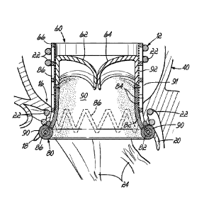
be actual heart valve tissue from an animal or more often the leaflets are
made
from pericardial tissue from cows, pigs or horses. These leaflets are treated
to
reduce their immunogenicity and improve their durability. Many tissue
processing techniques have been developed for this purpose. In the future,
biologically engineered tissue may be used or polymers or other non-biologic
materials may be used for valve leaflets. All of these can be incorporated
into
the inventions described in this disclosure.
[0007] There are, in fact, more patients with mitrel valve disease
than
aortic valve disease. In the course of the last decade, many companies have
been successful in creating catheter or minimally invasive implantable aortic
valves, but implantation of a mitrel valve is more difficult and to date there
has
been no good solution. Patients would be benefited by implanting a device by a
surgical procedure employing a small incision or by a catheter implantation
2
Date Recite/Date Received 2023-04-03
such as from the groin. From the patient's point of view, the catheter
procedure
is very attractive. At this time there is no commercially available way to
replace
the mitrel valve with a catheter procedure. Many patients who require mitrel
valve replacement are elderly and an open heart procedure is painful, risky
and
takes time for recovery. Some patients are not even candidates for surgery due
to advanced age and frailty. Therefore, there exists a particular need for a
remotely placed mitrel valve replacement device.
[0008] While previously, it was thought that mitrel valve replacement
rather than valve repair was associated with a more negative long-term
prognosis for patients with mitrel valve disease, this belief has come into
question. It is now believed that the outcome for patients with mitrel valve
leak
or regurgitation is almost equal whether the valve is repaired or replaced.
Furthermore, the durability of a mitrel valve surgical repair is now under
question. Many patients, who have undergone repair, redevelop a leak over
several years. As many of these are elderly, a repeat intervention in an older
patient is not welcomed by the patient or the physicians.
[0009] The most prominent obstacle for catheter mitrel valve
replacement
is retaining the valve in position. The mitrel valve is subject to a large
cyclic
load. The pressure in the left ventricle is close to zero before contraction
and
then rises to the systolic pressure (or higher if there is aortic stenosis)
and this
can be very high if the patient has systolic hypertension. Often the load on
the
valve is 150mmHg or more. Since the heart is moving as it beats, the
movement and the load can combine to dislodge a valve. Also, the movement
and rhythmic load can fatigue materials leading to fractures of the materials.
Thus, there is a major problem associated with anchoring a valve.
[0010] Another problem with creating a catheter delivered mitrel
valve
replacement is size. The implant must have strong retention and leak
avoidance features and it must contain a valve. Separate prostheses may
contribute to solving this problem, by placing an anchor or dock first and
then
implanting the valve second. However, in this situation, the patient must
remain
stable between implantation of the anchor or dock and implantation of the
valve.
If the patient's native mitrel valve is rendered non-functional by the anchor
or
dock, then the patient may quickly become unstable and the operator may be
3
Date Recite/Date Received 2023-04-03
forced to hastily implant the new valve or possibly stabilize the patient by
removing the anchor or dock and abandoning the procedure.
[0011] Another problem with mitrel replacement is leak around the
valve,
or paravalvular leak. If a good seal is not established around the valve,
blood
can leak back into the left atrium. This places extra load on the heart and
can
damage the blood as it travels in jets through sites of leaks. Hemolysis or
breakdown of red blood cells is a frequent complication if this occurs.
Paravalvular leak was one of the common problems encountered when the
aortic valve was first implanted on a catheter. During surgical replacement, a
surgeon has a major advantage when replacing the valve as he or she can see
a gap outside the valve suture line and prevent or repair it. With catheter
insertion, this is not possible. Furthermore, large leaks may reduce a
patient's
survival and may cause symptoms that restrict mobility and make the patient
uncomfortable (e.g., short of breathe, edematous, fatigued). Therefore,
devices, systems, and methods which relate to mitrel valve replacement should
also incorporate means to prevent and repair leaks around the replacement
valve.
[0012] A patient's mitrel valve annulus can also be quite large. When
companies develop surgical replacement valves, this problem is solved by
restricting the number of sizes of the actual valve produced and then adding
more fabric cuff around the margin of the valve to increase the valve size.
For
example, a patient may have a 45mm valve annulus. In this case, the actual
prosthetic valve diameter may be 30mm and the difference is made up by
adding a larger band of fabric cuff material around the prosthetic valve.
However, in catheter procedures, adding more material to a prosthetic valve is
problematic since the material must be condensed and retained by small
delivery systems. Often, this method is very difficult and impractical, so
alternative solutions are necessary.
[0013] Since numerous valves have been developed for the aortic
position, it is desirable to avoid repeating valve development and to take
advantage of existing valves. These valves have been very expensive to
develop and bring to market, so extending their application can save
considerable amounts of time and money. It would be useful then to create a
mitrel anchor or docking station for such a valve. An existing valve developed
for the aortic position, perhaps with some modification, could then be
implanted
4
Date Recite/Date Received 2023-04-03
in the docking station. Some previously developed valves may fit well with no
modification, such as the Edwards Sapien TM valve. Others, such as the
Corevalve TM may be implantable but require some modification for an optimal
engagement with the anchor and fit inside the heart.
[0014] A number of further complications may arise from a poorly
retained or poorly positioned mitrel valve replacement prosthesis. Namely, a
valve can be dislodged into the atrium or ventricle, which could be fatal for
a
patient. Prior prosthetic anchors have reduced the risk of dislodgement by
puncturing tissue to retain the prosthesis. However, this is a risky maneuver
since the penetration must be accomplished by a sharp object at a long
distance, leading to a risk of perforation of the heart and patient injury.
[0015] Orientation of the mitrel prosthesis is also important. The
valve
must allow blood to flow easily from the atrium to the ventricle. A prosthesis
that enters at an angle may lead to poor flow, obstruction of the flow by the
wall
of the heart or a leaflet and a poor hemodynamic result. Repeated contraction
against the ventricular wall can also lead to rupture of the back wall of the
heart
and sudden death of the patient.
[0016] With surgical mitrel valve repair or replacement, sometimes
the
anterior leaflet of the mitrel valve leaflet is pushed into the area of the
left
ventricular outflow and this leads to poor left ventricular emptying. This
syndrome is known as left ventricular tract outflow obstruction. The
replacement valve itself can cause left ventricular outflow tract obstruction
if it is
situated close to the aortic valve.
[0017] Yet another obstacle faced when implanting a replacement
mitrel
valve is the need for the patient's native mitrel valve to continue to
function
regularly during placement of the prosthesis so that the patient can remain
stable without the need for a heart-lung machine to support circulation.
[0018] In addition, it is desirable to provide devices and methods
that can
be utilized in a variety of implantation approaches. Depending on a particular
patient's anatomy and clinical situation, a medical professional may wish to
make a determination regarding the optimal method of implantation, such as
inserting a replacement valve directly into the heart in an open procedure
(open
heart surgery or a minimally invasive surgery) or inserting a replacement
valve
from veins and via arteries in a closed procedure (such as a catheter-based
implantation). It is preferable to allow a medical professional a plurality of
Date Recite/Date Received 2023-04-03
implantation options to choose from. For example, a medical professional may
wish to insert a replacement valve either from the ventricle or from the
atrial
side of the mitre! valve.
[0019] Therefore, the present invention provides devices and methods
that address these and other challenges in the art.
Summary
[0020] In one illustrative embodiment, the invention provides a
system for
replacing a native heart valve including an expansible helical anchor formed
as
multiple coils adapted to support a heart valve prosthesis. At least one of
the
coils is normally at a first diameter, and is expandable to a second, larger
diameter upon application of radial outward force from within the helical
anchor. A gap is defined between adjacent coils sufficient to prevent
engagement by at least one of the adjacent coils with the native heart valve.
An
expansible heart valve prosthesis is provided and is configured to be
delivered
into the helical anchor and expanded inside the multiple coils into engagement
with the at least one coil. This moves at least that coil from the first
diameter to
the second diameter while securing the helical anchor and the heart valve
prosthesis together. The system further includes a seal on the expansible
heart
valve prosthesis configured to engage the helical anchor and prevent blood
leakage past the heart valve prosthesis after implantation of the heart valve
prosthesis in the helical anchor.
[0021] The system may include one or more additional aspects. For
example, the helical anchor may include another coil that moves from a larger
diameter to a smaller diameter as the heart valve prosthesis is expanded
inside
the multiple coils. The seal may take many alternative forms. For example, the
seal can include portions extending between adjacent coils for preventing
blood
leakage through the helical anchor and past the heart valve prosthesis. The
seal may be comprised of many different alternative materials. The seal may
further comprise a membrane or panel extending between at least two coils of
the helical anchor after implantation of the heart valve prosthesis in the
helical
anchor. For example, one example is a biologic material. The helical anchor
may further comprise a shape memory material. The heart valve prosthesis
includes a blood inflow end and a blood outflow end and at least one of the
ends may be unflared and generally cylindrical in shape. In an illustrative
6
Date Recite/Date Received 2023-04-03
embodiment, the blood outflow end is flared radially outward and includes a
bumper for preventing damage to tissue structure in the heart after
implantation. The gap may be formed by a coil portion of the helical anchor
that
extends non-parallel to adjacent coil portions of the helical anchor.
[0022] In another illustrative embodiment, a system is provided as
generally described above, except that the seal is alternatively or
additionally
carried on the helical anchor instead of being carried on the heart valve
prosthesis. Any other features as described or incorporated herein may be
included.
[0023] In another illustrative embodiment, a system for docking a
heart
valve prosthesis includes a helical anchor formed as multiple coils adapted to
support a heart valve prosthesis with coil portions positioned above and/or
below the heart valve annulus. An outer, flexible and helical tube carries the
coils of the helical anchor to form an assembly. A helical delivery tool
carries
the assembly and is adapted to be rotated into position through a native heart
valve. Additional or optional features may be provided. For example, a heart
valve prosthesis may be expanded inside the multiple coils. The outer tube
may be formed from a low friction material adapted to slide off of the
multiple
coils of the helical anchor after rotating into position through the native
heart
valve. The outer tube may be secured to the helical delivery tool with suture
or
by any other method. The helical delivery tool may formed with a plurality of
coils, and the outer tube may further be secured to the distal end. The distal
end may further comprise a bullet or tapered shape to assist with delivery.
The
distal end can further comprise a resilient element, and the distal ends of
the
outer tube and the helical delivery tube are secured to the resilient element.
[0024] In another illustrative embodiment, a system for replacing a
native
heart valve includes a helical anchor formed as multiple coils adapted to
support a heart valve prosthesis at the native heart valve. An expansible
heart
valve prosthesis is provided in this system and is capable of being delivered
into the helical anchor and expanded inside the multiple coils into engagement
with the at least one coil to secure the helical anchor and the heart valve
prosthesis together. A guide structure on the expansible heart valve
prosthesis
7
Date Recite/Date Received 2023-04-03
is configured to guide the helical anchor into position as the helical anchor
is
extruded from a helical anchor delivery catheter.
[0025] The guide structure may further comprise an opening within a
portion of the expansible heart valve prosthesis, such as an opening in a
loop, a
tube or simply an opening in the stent structure of the expansible heart valve
prosthesis, for example. The opening may be configured to receive a helical
anchor delivery catheter that carries the helical anchor during the
implantation
procedure. The opening may be located on an arm of the expansible heart
valve prosthesis and the prosthesis may further comprise a plurality of arms
configured to engage beneath the native heart valve. The guide structure may
further comprise a tubular arm of the expansible heart valve prosthesis.
[0026] In another illustrative embodiment, a system for docking a
mitrel
valve prosthesis and replacing a native mitrel valve is provided and includes
a
coil guide catheter and a helical anchor adapted to be received in and
delivered
from the coil guide catheter. The helical anchor is formed as multiple coils
having a coiled configuration after being delivered from the coil guide
catheter
and adapted to support the mitrel valve prosthesis upon being fully delivered
from the coil guide catheter and implanted at the native mitre! valve. The
system further includes a tissue gathering catheter including loop structure
configured to be deployed to surround and gather the native chordea tendinae
for allowing easier direction of the helical anchor in the left ventricle.
[0027] In another illustrative embodiment, an anchor for docking a
heart
valve prosthesis includes an upper helical coil portion, a lower helical coil
portion, and a fastener securing the upper helical coil portion to the lower
helical
coil portion.
[0028] In another illustrative embodiment, a method of implanting a
heart
valve prosthesis in the heart of a patient includes holding a helical anchor
in the
form of multiple coils within an outer, flexible tube. The assembly of the
outer,
flexible tube and the helical anchor is secured to a helical delivery tool.
The
helical delivery tool is rotated adjacent to a native heart valve of the
patient to
position the assembly on either or both sides of the native heart valve. The
assembly is removed from the helical delivery tool, and the outer tube is
8
Date Recite/Date Received 2023-04-03
removed from the helical anchor. The heart valve prosthesis is then implanted
within the helical anchor.
[0029] Securing the assembly may further comprise positioning coils
of
the assembly generally along adjacent coils of the helical delivery
tool. Removing the outer tube may further comprise holding the helical anchor
with a pusher element, and pulling the outer tube off the helical anchor.
[0030] In another illustrative embodiment, a method of implanting an
expansible heart valve prosthesis in the heart of a patient includes
delivering an
expansible helical anchor in the form of multiple coils proximate the native
heart
valve. The expansible heart valve prosthesis is positioned within the multiple
coils of the expansible helical anchor with the expansible heart valve
prosthesis
and the expansible helical anchor in unexpanded states. The expansible heart
valve prosthesis is expanded against the expansible helical anchor thereby
expanding the expansible heart valve prosthesis while securing the expansible
heart valve prosthesis to the expansible helical anchor. A seal is carried on
the
helical anchor and/or on the heart valve prosthesis and extends between at
least two adjacent coils for preventing blood leakage through the helical
anchor
and past the heart valve prosthesis.
[0031] In another illustrative embodiment, a method of implanting an
expansible heart valve prosthesis to replace a native heart valve of a patient
includes delivering a helical anchor in the form of multiple coils proximate
the
native heart valve. The expansible heart valve prosthesis is delivered
proximate the native heart valve. The helical anchor is guided generally
around
a periphery of the expansible heart valve prosthesis using guide structure
carried on the expansible heart valve prosthesis. The expansible heart valve
prosthesis is expanded against the helical anchor. As discussed above, the
guide structure may take many different forms.
[0032] In another illustrative embodiment, a method of implanting a
helical anchor for docking a mitrel heart valve prosthesis in a patient
includes
gathering the chordea tendinae using a tissue gathering catheter. A helical
anchor is then delivered in the form of multiple coils proximate a native
heart
valve and around the gathered chordae tendinae.
[0033] In another illustrative embodiment, a method of implanting a
helical anchor for docking a heart valve prosthesis in a patient includes
delivering an upper helical anchor portion comprised of upper coils to a
position
9
Date Recite/Date Received 2023-04-03
above a native heart valve, and delivering a lower helical anchor portion
comprised of lower coils to a position below the native heart valve. The upper
and lower helical anchor portions are secured together with a fastener either
before or after delivery of each helical anchor portion.
[0034] In another illustrative embodiment, a system for replacing a
native
heart valve is provided and includes an expansible helical anchor formed as
multiple coils adapted to support a heart valve prosthesis. At least one of
the
coils is normally at a first diameter, and is expandable to a second, larger
diameter upon application of radial outward force from within the helical
anchor. A gap is defined between adjacent coils sufficient to prevent
engagement by at least one of the adjacent coils with the native heart valve.
An
expansible heart valve prosthesis is provided and is capable of being
delivered
into the helical anchor and expanded inside the multiple coils into engagement
with the at least one coil. In this manner, the expansible coil moves from the
first diameter to the second diameter while securing the helical anchor and
the
heart valve prosthesis together. The expansible heart valve prosthesis
includes
an inflow end and an outflow end. The inflow end is unflared and generally
cylindrical, while the outflow end is flared in a radially outward direction.
[0035] Various additional advantages, methods, devices, systems and
features will become more readily apparent to those of ordinary skill in the
art
Date Recite/Date Received 2023-04-03
upon review of the following detailed description of the illustrative
embodiments
taken in conjunction with the accompanying drawings.
Brief Description of the Drawings
[0036] FIG. 1 is a perspective view schematically illustrating the
introduction of a helical anchor to the position of the native mitre! valve.
[0037] FIG. 2A is an enlarged cross-sectional view illustrating an
initial
portion of the procedure shown in FIG. 1, but with use of a deflectable
catheter.
[0038] FIG. 2B is a cross-sectional view of the heart similar to FIG.
2A,
but illustrating deflection of the delivery catheter and introduction of the
helical
anchor underneath the native mitre! valve.
[0039] FIGS. 3A and 3B are enlarged elevational views illustrating
the
distal end of the delivery catheter and its deflecting capability.
[0040] FIGS. 4A and 4B are respective top views of FIGS. 3A and 3B.
[0041] FIG. 5A is a side elevational view similar to FIG. 3B, but
illustrating the use of a wire within the delivery catheter used for
deflecting or
steering the distal end.
[0042] FIG. 5B is a cross-sectional, top view of the delivery
catheter
shown in FIG. 5A.
[0043] FIG. 6A is a perspective view showing the combination of a
helical
anchor and an outer tube used for assisting with the delivery of the helical
anchor to the native mitrel valve location.
[0044] FIG. 6B is a perspective view of the helical anchor within the
outer
tube shown in FIG. 6A.
[0045] FIG. 7A is an elevational view showing a helical delivery tool
used
to deliver the assembly of FIG. 6B to the native mitrel valve location.
[0046] FIG. 7B is a perspective view illustrating the attachment of
the
assembly shown in FIG. 6B to the helical delivery tool shown in FIG. 7A.
[0047] FIG. 8A is a perspective view showing the heart in cross
section
and the helical delivery tool being used to implant the assembly of FIG. 6B.
[0048] FIGS. 8B through 8E are perspective views showing further
steps
in the method of implantation.
[0049] FIG. 8F is a perspective view showing the implanted helical
anchor.
11
Date Recite/Date Received 2023-04-03
[0050] FIG. 8G is a cross-sectional view showing a replacement heart
valve, such as a stent mounted valve, within the implanted helical anchor.
[0051] FIG. 9 is a perspective view illustrating another illustrative
embodiment of a tool and assembly for implanting a helical anchor.
[0052] FIG. 10 is a partially cross-section top view showing the
assembly
of FIG. 9.
[0053] FIG. 11A is a cross-sectional view of the distal end of an
alternative embodiment of a helical anchor and delivery catheter.
[0054] FIG. 11B is a perspective view of the distal end of another
embodiment of a helical anchor and delivery catheter.
[0055] FIG. 12 is a cross-sectional view of an implanted replacement
stent mounted valve and helical anchor at a native mitrel valve location
according to another illustrative embodiment.
[0056] FIG. 13 is an enlarged cross-sectional view showing another
illustrative embodiment of a stent mounted replacement heart valve.
[0057] FIG. 13A is an enlarged cross-sectional view showing a non-
flared
embodiment of the outflow end of the replacement heart valve shown in FIG.
13.
[0058] FIG. 14A is a cross-sectional view illustrating another
illustrative
embodiment of a replacement heart valve secured within a helical anchor.
[0059] FIG. 14B is an enlarged cross-sectional view of the
replacement
valve shown in FIG. 14A.
[0060] FIG. 15A is a schematic view showing a heart in cross section
and
initial introduction of a delivery catheter to the mitrel valve location.
[0061] FIG. 15B is an enlarged cross-sectional view of the heart
showing
a further step in the introduction of a stent mounted replacement heart valve
together with a helical anchor.
[0062] FIGS. 15C through 15F are views similar to FIG. 15B, but
illustrating progressively further steps in the method of introducing the
helical
12
Date Recite/Date Received 2023-04-03
anchor and stent mounted replacement heart valve at the native mitrel valve
location.
[0063] FIGS. 16A and 16B are schematic elevational views showing the
simultaneous deployment of a stent mounted replacement heart valve and a
helical anchor using an arm with a loop on the stent valve.
[0064] FIGS. 17A and 17B are similar to FIGS. 16A and 16B, but
illustrate another embodiment.
[0065] FIGS. 18A, 18B and 18C are views similar to FIGS. 16A and 16B,
however, these views progressively illustrate another embodiment of a method
for deploying a helical anchor and a stent mounted replacement heart valve.
[0066] FIG. 19A is a side elevational view of a helical anchor
constructed
in accordance with another illustrative embodiment.
[0067] FIG. 19B is a cross-sectional view taken along line 19B-19B of
FIG. 19A.
[0068] FIG. 20 is a schematic perspective view illustrating another
alternative system for delivering a helical anchor.
[0069] FIG. 21A is a schematic perspective view illustrating the
initial
delivery of an alternative helical anchor.
[0070] FIG. 21B is a schematic perspective view of the fully
delivered
helical anchor of FIG. 21A.
[0071] FIG. 22A is a cross-sectional view showing another
illustrative
embodiment of a helical anchor including a seal.
[0072] FIG. 22B is a cross-sectional view similar to FIG. 22A, but
showing the helical anchor implanted at the location of a native mitrel valve
and
an expandable stent mounted replacement valve held within the helical anchor.
[0073] FIG. 23A is a schematic elevational view showing another
illustrative embodiment of a helical anchor before expansion with a balloon
catheter.
[0074] FIG. 23B is an elevational view similar to FIG. 23A, but
illustrating
the helical anchor during expansion by the balloon catheter.
Detailed Description of the Illustrative Embodiments
[0075] It will be appreciated that like reference numerals throughout
this
description and the drawings refer generally to like elements of structure and
function. The differences between embodiments will be apparent from the
13
Date Recite/Date Received 2023-04-03
drawings and/or from the description and/or the use of different reference
numerals in different figures. For clarity and conciseness, description of
like
elements will not be repeated throughout the description.
[0076] Referring first to FIG. 1 in conjunction with FIGS. 2A and 2B,
as
previously discussed in Applicant's PCT Application Serial No.
PCT/U52013/024114, a deflectable catheter 10 makes implantation of a helical
anchor 12 much easier. The deflectable tip 10a of the catheter 10 assists with
the helical anchor 12 engaging a commissure 14 of the native mitre! valve 16,
as shown in FIG. 1. The tip 10a of the catheter 10 may be designed and
configured such that it can bend downward toward the native leaflets 18, 20 of
the mitre! valve 16. Once the tip 10a of the catheter 10 is placed generally
over
the commissure 14 as shown in FIG. 2A, the tip or distal end 10a may be bent
downward and it is then relatively easy to push or extrude the helical anchor
12
out of the distal end 10a and downward through the mitre! valve 16 as shown in
FIG. 2B.
[0077] Now referring to FIGS. 3A, 3B, 4A, 4B, 5A and 5B, the
deflectable
catheter, or anchor delivery catheter 10, may be deflectable at many different
points or locations. Deflecting the catheter tip 10a outward to increase the
radius of the delivery catheter tip 10a can be very helpful, as shown in FIGS.
3A, 3B and 4A, 4B which show the "before" and "after" effects of deflecting
the
distal end 10a. Deflecting the catheter 10 in this way will give the helical
anchor
12 a larger diameter starting turn or coil 22. As an example, this turn or
coil 22
of the helical anchor 12 may normally be 25mm but operating the distal end 10a
of the catheter 10 in this manner can enlarge the diameter to 30mm. Opening
up the first turn or coil 22 of the helical anchor 12 in this way would help
the
helical anchor 12 capture all chordae 24 and leaflets 18, 20 as the helical
anchor 12 is introduced as generally discussed above in connection with FIG. 1
and FIGS. 2A and 2B. As the helical anchor 12 advances, the distal end 10a of
the delivery catheter 10 could also deflect inward to help the helical anchor
12
capture all of the chordae 24 at the opposite commissure. Moving the distal
end 10a of the delivery catheter 10 from side to side as the helical anchor 12
is
essentially screwed or rotated into and through the native mitre! valve 16 is
essentially like tracking the delivery catheter 10 with the turn or coil 22.
In this
case, however, the delivery catheter 10 is stationary as only the tip 10a is
moving with the coils 22. Deflectability of the distal end 10a in any
direction
14
Date Recite/Date Received 2023-04-03
may be achieved by embedding a wire 26 that runs the length of the delivery
catheter 10. When the wire 26 is pulled, the delivery catheter tip 10a
deflects
and deforms into various shapes as desired or needed in the procedure.
[0078] A procedure will now be described for introducing or
implanting a
helical anchor 12 in connection with FIGS. 6A, 6B, 7A, 7B, and 8A through 8C.
A helical delivery tool 30 including coils 31 is used to deliver the helical
anchor
12 which is contained within an outer tube 32, for example, formed from a
Goretex or other low friction material, such as PTFE. Suture 34 is used to
secure the combination or assembly of the outer tube 32 and helical anchor 12
in place on the coils 31 of the helical delivery tool 30. A groove (not shown)
may be formed in the helical tool 30 so that it provides a secure seat for the
suture. Additional suture 36 is used to tie the leading end of the outer tube
32
through a loop 38 at the end of the helical delivery tool 30. The helical
delivery
tool 30 and outer tube/helical anchor combination 32, 12 is turned into the
heart
40, through the mitre! valve 16 as shown and the suture 34 is cut, for
example,
with a scalpel 42 (FIG. 8B). A pair of forceps 44 is used to turn the tool 30
in
through the native mitre! valve 16 slightly more and this breaks the suture 36
(FIG. 8C). The helical tool 30 is then rotated in an opposite direction and
removed from the heart 40, leaving the helical anchor 12 combined with the
outer tube 32 in the heart 40, as shown. A push rod 50 with a cupped end 52 is
inserted into the trailing end of the outer tube 32 (FIG. 8D). The outer tube
32
is then pulled backwards or rearward leaving the helical anchor 12 in place
while removing the outer tube 32. Due to the low friction material of the
outer
tube 32, it easily slides off of the helical anchor 12. FIGS. 8F and 8G,
respectively, show full implantation of this embodiment of the helical anchor
12
and a replacement heart valve 60 mounted within and firmly against the helical
anchor 12. The replacement valve 60 includes leaflets 62, 64, and a body 66
which may be of any suitable design, such as an expandable stent design.
[0079] In another embodiment shown in FIGS. 9 and 10, a bullet shaped
head 70 is provided on the helical tool 30. There is a slit 72 on the bullet-
shaped head 70 that runs parallel to the helical shaped wire or coil 22
adjacent
to the head 70. The bullet-shaped head 70 is formed from resilient, polymer,
for
example, and the slit 72 opens and closes by way of this resiliency. Again,
the
outer tube 32 is fixed to the helical delivery tool 30 with a suture (not
shown).
The leading end 32a of the outer tube 32 is inserted into the bullet-shaped
head
Date Recite/Date Received 2023-04-03
70, for example, with forceps 44. In this embodiment, the bullet-shaped head
70 provides for easier insertion due to its tapered shape.
[0080] FIGS. 11A and 11B show additional illustrative embodiments of
the combination of a delivery catheter 10 with a helical anchor 12 inside,
before
deployment. The distal tip 10a of the delivery catheter 10 includes a taper
which may be gradually tapered as shown in FIG. 11A, or more rounded as
shown in FIG. 11B. In each case, the distal tip 10a configuration allows for
smoother, easier delivery to a native mitrel valve location and can maneuver
through tissue structure, such as native tissue, within the heart 40. For
example, the distal end 10a of the delivery catheter 10 may be directed
through
the mitre! valve 16 and may need to encircle the chordae 24 either partially
or
fully (FIG. 1). As shown in FIG. 11A, the helical anchor 12 may be constructed
with an internal wire coil 12a and an external covering or coating 12b such as
fabric, and may include a soft tip 12c, such as formed from polymer, to avoid
damage to heart tissue during delivery and to enable easier delivery.
[0081] FIG. 12 is a cross-sectional view showing an illustrative
stent
mounted replacement heart valve or prosthesis 60 at the native mitre! valve 16
location docked in a helical anchor 12. In this embodiment, a "bumper"
structure 80 has been added to the annular edge at the outflow end of the
valve
60. This bumper structure 80 may be formed, for example, from foam 82
covered by a sealing material 84 such as fabric or another suitable material
or
coating. This sealing layer 84 extends upward over an open stent structure 86
of the valve 60 to prevent blood leakage past the valve 60 and through the
coils
22 of the helical anchor 12.
[0082] FIG. 13 is an enlarged view of a replacement heart valve 60
similar to the valve shown in FIG. 12, but showing radially outward flared
inflow
and outflow ends.
[0083] FIG. 13A is an enlarged sectional view showing a generally
cylindrical outflow end, without a radially outward flare.
[0084] FIGS. 14A and 14B illustrate another illustrative embodiment
of
the invention including a helical anchor 12 docking or mounting a replacement
stent valve 60 and including biological tissue seal 90, such as pericardium
tissue or other animal tissue used at both the location of the bumper 80 to
cover
the internal foam layer 82, as well as to seal and cover the open stent
structure
86 up to the location of an existing fabric layer 92 circumscribing the
16
Date Recite/Date Received 2023-04-03
replacement heart valve 60. The combination of the existing fabric layer 92 on
the stent valve 60 and the seal layer 90 circumscribing the lower or outflow
portion of the valve 60 prevents blood flow from leaking past the valve 60
through the stent structure 86. Instead, the blood passes as it should through
the leaflets 62, 64 of the replacement valve 60. As further shown in FIG. 14A,
the helical anchor 12 is preferably formed of spaced apart coils 22 creating a
gap 91 such as configured in any embodiment previously discussed in
connection with PCT Application Serial No. PCT/U52014/050525, or spaced
apart or formed as otherwise desired. As further described in
PCT/U52014/050525, the helical anchor 12 is expansible by the stent valve 60.
[0085] Referring to FIGS. 15A-15C, an initial portion of a procedure
according to another illustrative embodiment is shown. In this figure, a
sheath
100 and delivery catheter 101 have been advanced through a peripheral vein
into the right atrium 102 of the heart 40, across the atrial septum 104, to
the left
atrium 106. A distal end 10a of the delivery catheter 101 is positioned in the
left
ventricle 108 by being directed through the native mitre! valve 16. This
delivery
catheter 101 contains a self-expanding or stent mounted mitrel prosthesis or
replacement valve 60 that is to be implanted at the location of the native
mitre!
valve 16. A super elastic or shape memory type material, such as Nitinol, is
typically used to form the frame structure or body 66 of the self-expanding
replacement valve 60, but other materials may be used instead. The frame or
body 66 includes artificial valve leaflets 18, 20 typically formed from tissue
such
as pericardial cow or pig tissue. Leaflets 18, 20 could instead be formed of
other materials, such as synthetic or other biomaterials, e.g., materials
derived
from small intestinal mucosa. As described further below, the delivery
catheter
101 also contains a helical anchor 12 and delivery system. The helical anchor
12 may generally take the forms described herein or previously disclosed, for
example, in PCT Application Serial Nos. PCT/U52014/050525 and
PCT/I B2013/000593.
[0086] FIG. 15B illustrates the delivery catheter 101 inside the left
ventricle 108 with the distal tip 10a just below the native mitrel valve
leaflets 18,
20. The procedure has been initiated with exposure of the contents of the
delivery system.
[0087] FIG. 15C illustrates another portion of the procedure
subsequent
to FIG. 15B and illustrating that the prosthetic or replacement mitre! valve
60
17
Date Recite/Date Received 2023-04-03
has been partially delivered through the distal end 10a of the catheter 101.
The
end of the replacement valve 60 that is positioned in the left ventricle 108
has
arms 110 that wrap around the native mitre! leaflets 18, 20 and serve to
anchor
the replacement valve 60 firmly against the margins of the native mitrel valve
leaflets 18, 20. The arrows 112 show how the arms 110 have wrapped around
the lower margins of the native mitre! leaflets 18, 20 after the arms 110 have
been extruded or deployed outwardly from the delivery catheter 101. This
replacement valve 60 construction has been shown in the above-incorporated
PCT Application Serial No. PCT/IB2013/000593. These arms 110 will help
prevent the replacement valve 60 from dislodging upward into the left atrium
106 when the replacement valve 60 is fully positioned, because the arms 110
hook around the edges of the native mitre! leaflets 18, 20. Multiple arms 110
are useful to provide a lower plane of attachment of the mitrel valve
prosthesis
60 to the native mitre! valve 16. The arms 110 may vary in length and in
character and construction. It will be understood that a plurality of arms 110
is
used with this embodiment, but only two arms 110 are shown in these figures
for purposes of illustration and simplification. One of the arms 110 includes
a
loop 120 to direct or control the helical anchor delivery catheter 10 that
contains
a helical anchor 12. The anchor delivery catheter 10 has been preloaded into
the loop 120 before the assembly was loaded into the delivery sheath 100. The
arm with the loop 120 may be of heavier construction than the other arms 110
and does not have to resemble the other arms 110. The arms 110 have shape
memory property such that when they are extruded or deployed outwardly from
the anchor catheter 10 they wrap around the native mitre! leaflets 18, 20. The
arm 110 with the loop 120 wraps around the native mitre! leaflets 18,20 and
the
attached helical anchor delivery catheter 10 is carried with it so that the
chordae
24 and the native mitrel valve leaflets 18, 20 are positioned inside the
exposed
end of the helical anchor 12.
[0088] When the
helical anchor 12 is advanced or extruded as is initially
shown in FIG. 15C, it will encircle the chordae tendinae 24 so that all valve
and
chordae will be trapped inside the helical anchor 12. The loop 120 swings the
helical anchor delivery catheter 10 around the native mitre! leaflets 18,20
and
above the chordae 24 into a preferred position under the native mitrel valve
annulus 126. The arm 110 with the loop 120 may have a dual function of
attachment of the valve 60 to the native leaflet margin and for guidance
during
18
Date Recite/Date Received 2023-04-03
delivery of the helical anchor 12. The loop 120 may be sufficiently large to
allow the helical anchor delivery catheter 10 to pivot or swivel as the system
is
deployed. It is important for the helical anchor 12 to be extruded in a plane
close to parallel to the underside of the native mitre! valve 16. The helical
anchor delivery catheter 10 is also aimed or oriented to this plane by the
loop
120. The loop 120 may, in fact, be composed of a short tube (not shown)
instead of a wire as shown. A tube would force the helical anchor delivery
catheter 10 into a favorable plane and orientation. Alternatively, the helical
anchor delivery catheter 10 could be steerable in one of the manners known
through steerable catheter technology.
[0089] Other mitrel valve prosthesis or replacement valves may be
used
and have a wide range of attachment arms or wings, or stent structure, that
wrap around the native mitrel valve leaflets 18, 20. The arms or other similar
structures in such prostheses could all be fitted with a loop 120, or tube or
other
similar guidance structure, to perform similar functions as the loop 120
described immediately above. This function generally relates to directing the
delivery of the helical anchor 12. Furthermore, it is not necessary that a
loop
120 directs the helical anchor delivery. For example, a cell or opening of the
replacement valve stent structure 86 could also perform the same function as
the loop 120 shown and described in these figures. A hook or a tube may also
be used in lieu of the illustrated loop 120. Any structure that can function
to
direct the helical anchor 12 around the native mitrel valve leaflets 18, 20
may be
added to the prosthetic or replacement heart valve 60. The structure may be
permanently fabricated as part of the replacement valve 60 or may be
temporary structure used only during the procedure. For example, a loop of
suture (not shown) may be used to guide delivery of a helical anchor 12
including any helical anchor delivery catheter 10 associated therewith. After
use of the suture, it may be withdrawn from the patient.
[0090] The arms 110 illustrated in these figures are quite narrow or
slender. In practice, it may be more useful to have arms that are composed of
pairs or triplets of wires that are fused at the ends. The narrow terminal
ends of
the arms 110 facilitate the arms 110 passing between the chordae tendinae 24
at their margins with the free edge of the native mitre! leaflets 18, 20 to
allow
the arms 110 to wrap around the native leaflets 18, 20. The chordae 24 are
closely packed in some areas and slender arms 110 will allow the arms 110 to
19
Date Recite/Date Received 2023-04-03
pass between the chordae tendinae 24. Once the slender portion of the arms
110 pass, thicker portions of the arms 110 may move between the chordae 24
by spreading them apart. Therefore, an arm 110 that is slender or composed of
a single wire or fusion of wires at the tip and that is more robust or thicker
closer
to the main body of the prosthetic or replacement valve 60, may be a desirable
arrangement. The wires or arms 110 may also be much shorter than those
shown in these illustrative figures. In the illustrated method, delivery of
the
helical anchor 12 may be started at any desired location and not necessarily
at
the commissure 14 of the native mitre! valve 16. For example, delivery may
start in the middle portion of a native mitre! leaflet 18 or 20. This would be
advantageous for the surgeon who would not have to precisely locate the
comm issure 14 to begin the procedure, thereby greatly simplifying the
procedure.
[0091] FIG. 15D illustrates the helical anchor 12 being delivered
under
the native mitre! leaflets 18, 20. The arrow 130 indicates the helical anchor
12
being extruded from the helical anchor delivery catheter 10 under the native
mitre! valve 16. Any number of coils or turns 22 of the helical anchor 12 may
be
extruded depending on the particular configuration of helical anchor 12 being
used in the procedure. The inner diameter of the helical anchor 12 would
preferentially be slightly less than the outer diameter of the fully expanded
mitrel
valve prosthesis 60 to promote firm engagement or anchoring of the
replacement mitre! valve 60. The helical anchor 12 may be composed of bare
wire, or may have coatings or coverings for various reasons such as those
described in the above incorporated PCT applications. The partially delivered
mitrel valve prosthesis 60 serves an important function to center the delivery
of
the helical anchor 12. The mitrel valve prosthesis or replacement valve 60
also
provides a stable platform.
[0092] FIG. 15E illustrates that three turns 22 of the helical anchor
12
have been placed below the native mitre! valve 16. These turns or coils 22
have positioned the native mitrel valve leaflets 18, 20 between the helical
anchor 12 and the prosthetic mitre! valve 60 which is shown in a configuration
about to be expanded. Once the replacement valve 60 is expanded, this
securely positions the replacement valve 60 and prevents leaks around the
replacement valve 60 by sealing the native mitre! leaflets 18, 20 to the
prosthesis 60. The delivery sheath 101 for the replacement valve 60 has been
Date Recite/Date Received 2023-04-03
removed and when using a self-expanding valve, the valve 60 would spring
open upon removal of the delivery sheath 101. The arrows 132 indicate this
process prior to its occurrence. In this figure, the replacement valve 60 is
still in
a closed position to allow clear visualization of the turns or coils 22 of the
helical
anchor 12 beneath the native mitre! valve 16. In this configuration, there are
three helical anchor coils 22 below the native mitre! valve 16, however, any
number of coils 22 may be used instead. The coils 22 are positioned up against
the underside of the mitrel valve annulus 126 and leaflets 18,20 to provide a
solid buttress to fix the helical anchor 12 in position and prevent movement
into
the left atrium 106 when the powerful left ventricle 108 contracts. When the
arms 110 wrap around the helical anchor 12, the entire structure or assembly
is
stabilized in position. This embodiment provides a surgeon or
interventionalist a
considerable amount of choice due to the fact that the anchor 12 may be
delivered at the same time as the replacement valve 60. Many shape memory
framed prosthetic heart valves 60 may be re-sheathed. This means that during
a procedure, the replacement valve 60 may be partially advanced from a
catheter or sheath 101 and tested for its fit in the heart 40. If the surgeon
or
interventionalist is not satisfied with the positioning of the replacement
valve 60
before the final release of the replacement valve 60, this valve 60 may be
pulled
back into the sheath or catheter 101. Therefore, a prosthetic or replacement
valve 60 may be positioned initially with no helical anchor 12 in place. If
subsequent anchoring appeared strong and stable and there was no evidence
of movement or leakage, the valve 60 may be released. On the other hand, if
the surgeon or interventionalist is not satisfied, the valve 60 may be pulled
back
into the sheath 101. The helical anchor 12 may be implanted first, and then
the
valve 60 may be extruded from the delivery sheath 101. This would allow the
user to decide on the clinical need for additional anchoring under the native
mitre! valve 16.
[0093] FIG. 15F illustrates the fully implanted expandable
replacement
valve 60 shown in proper position. The arms 110 have wrapped around the
native mitrel valve leaflets 18, 20 to prevent the replacement valve 60 from
moving upward into the left atrium 106. The native mitre! leaflets 18, 20 are
compressed under the arms 110 and a very solid mechanical structure and
anchoring has been created to prevent the replacement valve 60 from migrating
to an undesirable position. The turns or coils 22 of the helical anchor 12
also
21
Date Recite/Date Received 2023-04-03
compress against the body 66 of the prosthetic or replacement valve 60 to
position, orient and prevent movement of the replacement valve 60. Therefore,
the helical anchor 12 provides a friction attachment of the replacement valve
60
and serves to anchor the arms 110 that wrap around the helical anchor 12. The
upper portion of the native mitre! valve 16 is shown with a wider area that
sits
inside the left atrium 106 to promote attachment to the wall of the left
atrium
106. However, the force moving the replacement valve 60 from the left atrium
106 toward the left ventricle 108 is low and this portion of the replacement
valve
60 may not be necessary and could be eliminated or reduced from a clinical
prosthesis. The turns or coils 22 of the helical anchor 12 are important
because
they can overcome a wide variety of variations in the lengths of the native
mitre!
leaflets 18, 20 from patient to patient and the length of the chordae tendinae
24
and the attachment points of the chordae 24 in the left ventricle 108. When a
replacement valve 60 with arms 110 wrapping around the native mitre! leaflets
18,20 is used without any helical anchor 12 encircling under the native
leaflets
18, 20, the depth of fixation of the prosthetic mitre! valve 60 may vary
around
the perimeter of the implanted replacement valve 60. For example, if the
chordae tendinae 24 attached to the middle part of the posterior leaflet 20
were
very elongated or ruptured, which is a common situation, the arms 110 may fail
to wrap around and engage the native leaflet 20 at this location.
Alternatively,
there may be a very limited engagement along or at a much higher plane. This
portion of the replacement valve 60 would be positioned higher, creating a
skew
in the replacement valve 60 so that the replacement valve 60 would be
positioned at an angle to the plane of inflowing blood through the replacement
valve 60. As the heart 40 beats, there is a large load on the replacement
valve
60 and it may begin to rock and shift. The heart 40 beats almost 100,000 times
per day and after several days or weeks or months, the valve 60 may shift,
move and/or dislodge. Also, if the leaflets 18, 20 and/or chordae 24 were very
elongated, there may be no contact with the arms 110. This could result in a
large perivalvular leak due to lack of engagement of the replacement valve 60
with the native mitre! leaflets 18, 20. An anchor 12 under the native mitrel
valve
leaflets 18, 20 would compress native leaflet tissue against the replacement
22
Date Recite/Date Received 2023-04-03
valve 60 and prevent this problem. The helical anchor 12 would be positioned
in one plane and prevent problems related to variations in patient anatomy.
[0094] In
clinical practice, there are virtually limitless variations in the size
of the native mitre! leaflets 18, 20, character of the native mitre! leaflets
18, 20,
the chordal lengths and the attachment of the chordae 24 as well as the
diameter of the mitre! annulus 126. The use of a helical anchor 12 or other
anchor structure under the native leaflets 18,20 neutralizes many of these
variables since the fixation point of the arms 110 may be brought to the
lowest
coil 22 of the helical anchor 12. This position may also be determined in
advance by selecting the number of coils 22 in the helical anchor 12 as well
as
the thickness of the coils 22 in the helical anchor 12 to match the turning
point
of the arms 110 on the lowest portion of the replacement valve 60. Thus, an
important feature of the helical anchor 12 delivered under the native mitre!
annulus 126 is that it can create a common and predefined plane for anchoring
the arms 110 of the replacement valve 60. In the situation described above in
which some of the chordae 24 are stretched, the attachment in this region of
the
replacement valve 60 could be to the helical anchor 12. This would create a
common plane for the lowest point on the replacement valve 60. To ensure that
the valve 60 anchors at a common lowest plane throughout its perimeter,
additional coils 22 may be added to the helical anchor 12, or the diameter of
the
coils 22 may be made larger. Additional options are, for example, waves or
undulations may be added to the coils 22 of the helical anchor 12 to expand
the
overall height of the helical anchor 12. The helical anchor 12 therefore
improves stability of the replacement valve 60 by providing an anchoring point
or location for the arms of the replacement valve 60 to wrap around while, at
the
same time, the helical anchor 12 can trap the perimeter of the replacement
valve 60 along its length. The combination of these features provides for
increased stability to the replacement valve 60 and can also seal the
replacement valve 60 against the native mitre! valve 16 to prevent
perivalvular
leakage of blood flow. As mentioned, the native mitrel valve and heart
structure
of patients comes in many varieties and combinations. It is not practical for
a
manufacturer to make different lengths and depths of anchoring arms 110 and
for the user to deliver these products optimally into position for each case.
Rather, it is much more practical to adjust for these variations by placing a
helical anchor 12 below the native mitre! valve 16 and using this to create a
23
Date Recite/Date Received 2023-04-03
lowest plane for the arms 110 to anchor against. The delivery system for the
helical anchor 12 may be any delivery or deployment system, for example,
described in the above-incorporated PCT applications. It will be appreciated
that such deployment methods and apparatus may be used to deliver the
helical anchor 12 such that the anchor 12 is positioned only below the native
mitre! valve 16 as shown herein.
[0095] FIGS. 16A and 16B illustrate another embodiment in which a
loop
120 is provided at the end of an arm 110 on the replacement valve 60 that
guides the helical anchor delivery catheter 10. This loop 120 allows the
delivery
catheter 10 to swivel as it is moved into position. In this embodiment, the
helical anchor delivery catheter 10 passes through the replacement valve 60
or,
in other words, within the replacement valve body 66, however, it may be
directed in manners other than that shown, and the helical anchor delivery
catheter 10 may be used for additional guidance along the path, such as by
being steerable after being directed through the loop 120 farther than as
shown
in FIGS. 16A and 16B for delivery of the helical anchor 12.
[0096] FIGS. 17A and 17B illustrate another embodiment in which a
helical anchor delivery tube 140 has been incorporated into the replacement
valve 60 instead of the helical anchor delivery catheter 10 previously
described.
In this embodiment, one arm of the replacement valve 60 is, in fact, the tube
140 that is loaded with and carries the helical anchor 12. When the tubular
arm
140 wraps around the native mitrel valve leaflet (not shown), the helical
anchor
12 is carried into the correct location and to the correct plane for delivery.
Any
structure on one of the arms 110 of the replacement valve 60 or any portion of
the replacement valve 60 that may guide the helical anchor 12 for delivery may
be used instead. In FIG. 17B, the helical anchor 12 has been extruded from the
tubular arm 140 for almost one complete rotation or turn. As previously
described, multiple turns or coils 22 of the helical anchor 12 may be deployed
in
this manner for ultimately securing the replacement valve 60 at the native
mitre!
valve 16 location generally as described above. The main difference with this
embodiment is that a helical anchor delivery catheter 10 is not needed.
[0097] FIGS. 18A through 18C illustrate another embodiment for
replacement valve and helical anchor deployment and implantation. In this
regard, the helical anchor delivery catheter 10 and the replacement valve 60
are essentially delivered side by side. FIG. 18A illustrates the helical
anchor
24
Date Recite/Date Received 2023-04-03
delivery catheter 10 outside or extruded from the delivery sheath 101 that
also
delivers the replacement valve 60. The helical anchor delivery catheter 10
passes through a loop 120 in one of the arms 110 of the replacement valve 60.
The arrow 150 indicates that the helical anchor 12 is about to be extruded
from
the end of the helical anchor delivery catheter 10. As shown in FIG. 18B, with
the end of the helical anchor delivery catheter 10 still in the loop 120,
almost
one full turn or coil 22 of the helical anchor 12 has been delivered under the
native mitre! valve (not shown). FIG. 18C illustrates a further point during
the
implantation process in which about three turns or coils 22 of the helical
anchor
12 have been delivered under the plane 152 of the native mitre! valve 16. In
this figure, the helical anchor delivery catheter 10 and the sheath 101
delivering
the replacement valve 60 have been removed. When the replacement valve 60
is formed with a self-expanding stent, the body 66 of the valve 60 will spring
open when the delivery sheath 101 is removed. For purposes of clarity and
illustration, the valve 60 is still shown in a closed or unexpanded state
simply for
clarity. However, in general, the fully implanted system or assembly will be
similar to that shown in FIG. 15F.
[0098] FIGS. 19A and 19B illustrate another embodiment of a helical
anchor 12. In this embodiment, the configuration of the helical anchor 12 in
terms of the spacings and size of the coils 22 may vary. The cross-sectional
construction includes a fabric covering 160 which may, for example, be PET
having a thickness of 0.008 +/- 0.002 inch, a weight of 2.12 +/- 0.18
ounce/yard2 (72 +/- 6 grams/m2), a wale/inch of 40 +/- 5, courses/inch of 90
+/-
10. A foam layer 162 may, for example, be 2mm thick polyurethane sheet
material. The foam may be attached to the fabric 160 using PTFE suture with a
light straight stitch. The fabric160 and foam 162 may then be folded around
the
center wire portion 22a of the coils 22 of the helical anchor 12 and cross-
stitched to the wire portion 22a using fiber suture.
[0099] FIG. 20 illustrates another system which may include the
delivery
of a helical anchor 12 as set forth above and/or in the above incorporated PCT
applications. In accordance with this embodiment, however, an additional
tissue gathering device 170 is included in the delivery system. The device 170
delivers a temporary ring or loop 172 which can corral or surround the bundles
of chordae tendinae 24 into a smaller area. This can facilitate easier
placement
of the helical anchor 12 without entanglement or obstruction with the chordae
Date Recite/Date Received 2023-04-03
tendinae 24. Also, shown in this figure is an introducer sheath 100, a
delivery
catheter 101 as well as a steerable helical anchor delivery catheter 10 all
generally as previously described.
[00100] FIGS. 21A and 21B illustrate another helical anchor device or
assembly 12. The assembly 12 is comprised of an upper or atrial helical anchor
portion 180 as well as a lower or ventricular helical anchor portion 182.
These
helical anchor portions 180, 182 are delivered simultaneously by extruding out
of a helical anchor delivery catheter 10. The lower anchor portion 182 is
delivered through the mitre! valve 16 between the native leaflets 18, 20. The
upper and lower anchor portions 180, 182 may be coupled together, for
example, by a crimp joint 184. The upper anchor portion 180 is deployed above
the native mitre! valve 16 in the left atrium 106 (FIG. 20). The upper and
lower
anchor portions 180, 182 may be staggered such that the lower anchor portion
182 is initially directed into the commissure 14 and through the native mitre!
valve 16. As shown, the upper and lower helical anchor portions 180, 182 wind
or rotate in opposite directions and then may be crimped together, as shown or
may be precrimped or otherwise attached prior to loading the catheter 10.
[00101] FIG. 22A and 22B illustrate another embodiment of a helical
anchor and replacement valve system similar to those discussed in connection
with the above-incorporated PCT Application Serial No. PCT/U52014/050525.
In this embodiment, however, the configuration of the helical anchor 12 is
shown to have a gap 200 between at least the upper coils 22a and the native
mitre! valve 16. As in the above incorporated PCT application, the helical
anchor 12 includes an annular seal 202 of any desired configuration extending
lengthwise through or otherwise along the length of the anchor 12. In this
embodiment, a panel or membrane seal 202 is shown extending downwardly
from one of the coils 22a and covering the portion of the stent mounted
replacement valve 60 that would otherwise be open due to the stent structure
86. The seal 202 therefore prevents leakage of blood past the replacement
valve 60 through the open stent structure 86. All other aspects of the
assembly
as shown in FIGS. 22A and 22B are as described herein and may include any
of the options or features described herein or otherwise, for example, in the
26
Date Recite/Date Received 2023-04-03
above-incorporated PCT applications. The gap 200 is formed by a coil portion
22b extending non-parallel to the adjacent coil portions 22a, 22c.
[00102] FIGS. 23A and 23B illustrate another embodiment of a helical
anchor 12, again similar to the above-incorporated PCT Application Serial No.
PCT/U52014/050525. The difference between this embodiment and the similar
embodiment shown in the above-incorporated PCT application is that a gap 200
has been created between two of the middle coils 22a, 22c of the anchor 12.
These two figures illustrate the feature of the helical anchor 12 in which the
coils 22 will move or rotate as the expandable anchor 12 is expanded by, for
example, a balloon catheter 210. As previously described, a gap 200 formed
between adjacent coils 22a, 22c may be used to ensure that native mitrel
tissue
is not trapped or engaged by the adjacent coils 22a, 22c. The gap 200 is
formed by a coil portion 22b extending non-parallel to the adjacent coil
portions
22a, 22c.
[00103] While the present invention has been illustrated by a
description
of preferred embodiments and while these embodiments have been described
in some detail, it is not the intention of the Applicants to restrict or in
any way
limit the scope of the appended claims to such detail. Additional advantages
and modifications will readily appear to those skilled in the art. The various
features and concepts of the invention may be used alone or in any
combination depending on the needs and preferences of the operator. This has
been a description of the present invention, along with the preferred methods
of
practicing the present invention as currently known. However, the invention
itself should only be defined by the appended claims.
27
Date Recite/Date Received 2023-04-03