Note: Descriptions are shown in the official language in which they were submitted.
CA 03195497 2023-03-14
Description
Medical syringe with needle guard
The invention relates to a medical syringe with needle protection having a
plunger
which is displaceable in the interior of a syringe body via an actuating
plunger.
To avoid or reduce the risk of contamination or injury after the use of
medicinal sy-
ringes and in particular to avoid multiple use of syringe needles by different
users,
syringes with so-called retraction or retraction systems for the syringe
needle are
increasingly used. In such syringes, in particular medical syringes, also
referred to
as "syringe with (passive) needle protection", the syringe needle is retracted
into
the syringe body after dispensing the active substance held in the syringe and
is
completely enclosed by the syringe body. Access to the syringe and thus a risk
of
injury, or even the risk of multiple use of the same needle, can thus be
largely ex-
cluded.
Such syringes with passive needle protection are known, for example, from EP 1
284 769 B1, EP 0 720 491 B1, EP 0 680 347 B1 or EP 1 764 127 B1.
Generally speaking, in the case of medical syringes, and thus also in the case
of
syringes with needle protection of the type mentioned, there is a need to
deliver
the active substance contained therein as completely as possible when using
the
syringe and to minimize as far as possible the retention of unused residual
quanti-
ties of the active substance within the syringe. The invention is now based on
the
task of specifying a syringe with needle protection of the above-mentioned
type,
with which this need is taken into account.
This task is solved according to the invention in that the plunger, which is
displace-
able in the interior of the syringe body, has a needle holder which is
provided for
receiving the syringe needle and whose needle bearing is arranged on a
retaining
bracket, leaving a number of lateral inflow surfaces free.
1
Date Recue/Date Received 2023-03-14
CA 03195497 2023-03-14
Advantageous embodiments of the invention can be taken from the subclaims
and/or the following description of the figures.
The invention is based on the consideration that the complete delivery of the
ac-
tive substance as a result of the displacement of the plunger within the
syringe
housing towards its distal end is essentially limited by the so-called dead
volume,
i.e. pockets or dead spaces within the housing due to the geometry, from which
the active substance can no longer flow out via the needle when the plunger is
completely displaced. For the intended minimization of the active substance
resi-
dues remaining in the syringe housing after use, these dead spaces should
there-
fore be kept particularly small, and outflow channels should be provided in a
tar-
geted manner, through which the active substance can still flow towards the
entry
end of the needle even when the plunger is pushed far forward. This can be
prob-
lematic, especially in syringes with needle protection, since in such systems
the
needle must be grasped when the plunger is far advanced and then retracted
with
the plunger into the interior of the syringe housing. The system for gripping
and
entraining the needle should therefore allow the active substance to flow as
far as
possible to the inner end of the needle, even when the plunger is advanced as
far
as possible. This is achieved by grasping the needle via a bracket that leaves
free
flow areas for the active substance in its lateral areas, through which the
active
substance can still flow to the needle.
Advantageously, the needle holder is made of plastic, preferably
polypropylene.
The polypropylene available under the designation "BormedTm" (HD810M0, ISO
10993 Information (Biocompatibility)) is particularly preferred as the basic
material
with regard to the expected required holding forces and the expected
mechanical
loads during intended use, but also with regard to approval-related
requirements.
Advantageously, the needle holder is surrounded by a plunger jacket which is
shaped in such a way that, when the needle holder is inserted, it leaves a
number
of inflow channels for the active substance at the side of the retaining clip.
The pis-
ton jacket is preferably made of rubber.
2
Date Recue/Date Received 2023-03-14
CA 03195497 2023-03-14
In a particularly preferred embodiment, the syringe body is manufactured as a
plastic part, preferably from cyclo-olefin polymer (COP). This material is
character-
ized by high breaking strength and glass-like transparency. Moreover, it does
not
release any alkali ions, so that the risk of a pH value shift in the active
ingredient
stored is excluded. Thus, according to the invention, this material is
considered
and used as suitable even for the primary packaging of demanding medicines, in
particular for sensitive biotechnologically produced active substances. In
addition,
this material is suitable for production by injection molding and thus for
particularly
precise dimensioning.
An embodiment of the invention is explained in more detail with reference to a
drawing. Shown therein:
Fig. 1 a medical syringe with needle protection,
Fig. 2 a side view of an actuation unit of the syringe according to Fig. 1,
Fig. 3 a cover plate of the syringe according to Fig. 1,
Fig. 4 the cover plate according to Fig. 3 with the actuating plunger
attached,
Fig. 5 a sequence of partial sections of the syringe according to Fig. 1,
Fig. 6A side view of a needle inserted into a needle holder for use in the
syringe
according to Fig. 1,
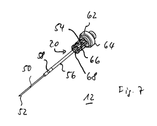
Fig. 7 the needle according to Fig. 6 in perspective view,
Fig. 8 a plunger of the syringe according to Fig. 1,
Fig. 9 an actuating plunger of the syringe according to Fig. 1,
Fig. 10 an alternative embodiment of a medical syringe with needle protection,
3
Date Recue/Date Received 2023-03-14
CA 03195497 2023-03-14
Fig. 11 a cartridge or cartridge unit of the syringe according to Fig. 10,
Fig. 12 a cap of the cartridge unit according to Fig. 11,
Fig. 13 an exploded view of the needle head of the syringe according to Fig.
10,
Fig. 14 a syringe frame of the syringe according to Fig. 10,
Fig. 15 the cartridge unit according to Fig. 11 immediately before (Fig. 15a)
and
after (Fig. 15b) insertion into the syringe frame according to Fig. 14,
Fig. 16 a longitudinal section of the connection area between the plunger and
the
actuating plunger of the syringe as shown in fig. 10,
Fig. 17 the syringe as shown in Fig. 10 with the needle attached and exposed,
Fig. 18 the syringe according to Fig. 10 after application of the active
substance
and retraction of the needle,
Fig. 19 the cartridge body of the syringe shown in Fig. 10 with the needle re-
tracted therein, and
Fig. 20 another alternative embodiment of a medical syringe with needle protec-
tion and double chamber system in longitudinal section.
Identical parts are marked with the same reference signs in all figures.
The medical syringe 1 with needle retraction according to Fig. 1 essentially
com-
prises two assemblies, namely on the one hand a cartridge unit 2 and on the
other
hand an actuating plunger 4 . In the embodiment example, the medical syringe 1
has a two-component design, with the two said assemblies forming separate com-
4
Date Recue/Date Received 2023-03-14
CA 03195497 2023-03-14
ponents that can be connected to one another in the manner described below. Al-
ternatively, the syringe could also have a single-component design, in which
case
the two assemblies mentioned are connected to each other from the outset and
the distinction between the two assemblies is merely functional.
The cartridge unit 2 forms the actual syringe and comprises a cylindrical or
tubular
hollow body 6 which forms a syringe housing and is intended to receive the
medi-
cal active substance. A needle holder 10 is attached to the front or distal
end 8 of
the hollow body 6, in which the hollow needle 12 intended for injecting the
active
substance is mounted in a bearing sleeve 14. The needle holder 10 could be
made in one piece with the hollow body 6 forming the syringe housing. In the
em-
bodiment example, however, the needle holder 10 is designed as a separate com-
ponent in an embodiment considered to be independently inventive. The needle
holder 10 is attached or attachable to the hollow body 6 forming the syringe
hous-
ing or to the syringe cone, but could also be screwed on by means of a thread,
for
example a Luer thread.
With regard to the choice of material for the syringe housing or the hollow
body 6
forming it, which is considered to be inventive in its own right, particular
account is
taken of high demands on the reliable temporary storage of the medical active
substance together with a particularly high level of safety in handling the
compo-
nents. The syringe body 6, which is designed as a cylindrical hollow body, is
made
of the high-performance plastic cyclo-olefin polymer in an embodiment
considered
to be inventive. This material is characterized by high breaking strength and
glass-
like transparency. Moreover, it does not release any alkali ions, so that the
risk of
a pH shift in the active ingredient is excluded. The syringe body 6 is
preferably
manufactured by injection molding, whereby, among other things, the molding is
carried out in such a way that possible dead volumes in the interior are kept
partic-
ularly low.
To prevent injuries or the like, the needle 12 is surrounded by a removable
protec-
tive cap, not shown in greater detail, which is removed before the syringe 1
is
Date Recue/Date Received 2023-03-14
CA 03195497 2023-03-14
used. The rear or proximal end 16 of the hollow body 6 forming the syringe
hous-
ing, on the other hand, can be closed by a piston 18 whose outer dimensions
are
precisely adapted to the inner contour of the hollow body 6 and which can be
moved within the hollow body 6. In the state shown in Fig. 1, i.e. with the
actuating
plunger 4 connected to the cartridge or cartridge unit 2 and before the
medicinal
substance is taken up or dispensed, the medicinal substance is thus enclosed
in
the interior of the hollow body 6 closed at the end by the piston 18. On its
end sur-
face facing the interior of the hollow body 6, the piston 18 has a central
receiving
hole 20 for the needle 12.
The drive or actuating plunger 4 comprises a shaft 28 provided on one end with
a
plunger plate 22 and on the other end 24 opposite the plunger plate 22 with a
cou-
pling element 26 provided for connection to the piston 18. With its shaft 28
extend-
ing between the plunger plate 20 and the coupling element 26, the actuating
plunger 4 is guided through a cover plate 30 in the assembled state of the
compo-
nents and is mounted in the latter so as to be displaceable in its
longitudinal direc-
tion.
The piston 18 could be made in one piece with the actuating plunger 4. In the
em-
bodiment example, however, these components are designed separately. As can
be seen from the illustration in Fig. 2, for connection to the shaft 28 of the
actuat-
ing plunger 4, the piston 18 has a fastening pin 36 molded on at the end and
pro-
vided with a circumferential groove. Corresponding to this and adapted in its
di-
mensioning to it, the coupling element 26 molded onto the end of the shaft 28
is
provided with an elongated hole 38 open on one side. The fastening pin 36 can
be
pushed laterally into this, so that the lateral edge of the elongated hole 38
engages
in the circumferential groove of the fastening pin 36 and thus, viewed in the
longi-
tudinal direction, a form fit is created between these components.
The medical syringe 1 is provided with a needle protection in the form of a
retrac-
tion system by the components and parts mentioned. The purpose of this is that
after use of the syringe 1, i.e. after dispensing the active substance held in
the hol-
low body 6 forming the syringe housing via the needle 12, the latter is drawn
into
6
Date Recue/Date Received 2023-03-14
CA 03195497 2023-03-14
the syringe housing in such a way that it is completely enclosed by the
syringe
housing. This is intended to keep unintentional contact with the used needle
12,
for example by auxiliary or nursing personnel, and thus the risk of injury and
con-
tamination particularly low or, if possible, completely excluded.
For this purpose, the following procedure is basically intended for the use
and han-
dling of the components mentioned:
The syringe 1 could in principle be used with a pre-filled cartridge or
cartridge unit
2. In this case, the cartridge or cartridge unit 2 filled with the active
ingredient
would be provided with the plunger 18 already inserted into the hollow body 6
and
closing its interior. As a first step in use, the actuating plunger 4 is then
connected
at the end to the piston 18 in the manner shown in Fig. 2, and the system is
ready
to dispense the active substance.
In the embodiment example, however, it is intended that the syringe 1 is made
ready for use when empty and is filled with the active substance by drawing it
on.
For this purpose, the actuating plunger 4 carrying the plunger 18 is first
inserted
into the receiving hole 40 provided for this purpose in the cover plate 30, so
that
the plunger 18 is introduced into the interior of the hollow body 6, as can be
seen
from the enlarged representation of the cover plate 30 from above at an angle
ac-
cording to Fig. 3 and of the cover plate 30 with the actuating plunger 4
attached
from above at an angle according to Fig. 4. The receiving hole 40 with its
outer
edge 42 designed in the manner of a guide slot and the corresponding cross-sec-
tion of the shaft 28 of the actuating plunger 4 are designed in such a way
that the
insertion takes place in a predetermined rotational alignment of the actuating
plunger 4 relative to the hollow body 6 or its cover plate 30.
Subsequently, the actuating plunger 4 is pressed by the operator while
maintaining
this rotational orientation - this is achieved by a constant cross-sectional
geometry
of the shaft 28, seen in the longitudinal direction - so that the piston 18
moves in-
side the hollow body 6 towards its distal end 8. As soon as a predetermined
end
7
Date Recue/Date Received 2023-03-14
CA 03195497 2023-03-14
position is reached in which the piston 18 is still sufficiently far away from
the nee-
dle 12 in the sense of the mechanism described below, this movement is stopped
by a stop formed by the shaft 28. The stop is formed by an abrupt change or
wid-
ening of the cross-section of the shaft 28 in the manner of a step or edge, as
seen
in the longitudinal direction, so that the shaft 28 cannot be guided further
through
the outer edge 42 of the receiving hole 40 in the longitudinal direction.
The cross-section of the shaft 28 and correspondingly the contour of the outer
edge 42 of the receiving hole 40, which forms the guide slot, are designed in
such
a way that when the piston 18 reaches the said end position inside the hollow
body 6, the rotational lock between the actuating plunger 4 and the cover
plate 30
is cancelled at least to a certain extent and the plunger 4 can be rotated in
the
cover plate 30 about its longitudinal axis through a predetermined angle of
rota-
tion, preferably about 90 . This rotation achieves that, on the one hand, the
previ-
ously present stop preventing further displacement of the plunger 18 in the
direc-
tion of the distal end 8 is unlocked, so that the plunger 18 could now be
pushed
completely into the final position within the hollow body 6. On the other
hand, how-
ever, this rotation also forms - again achieved by a suitable design of the
cross-
section of the shaft 28 and adapted thereto the contour of the outer edge 42 -
a
new stop "upwards" or towards the proximal end 16 of the hollow body 6, so
that
the actuating plunger 4 and in particular the piston 18 attached thereto at
the end
cannot be pulled out of the hollow body 6 beyond an end point predetermined
thereby.
In this position, the free end of the needle 12 is now inserted into an
external res-
ervoir of the active substance, and then the piston 18 is retracted in the
hollow
body 6 by means of the actuating plunger 4. The active substance is sucked in
via
the needle 12 and the interior of the hollow body 6 is thus filled.
After the syringe 1 has been made ready for use in one of the aforementioned
ways, the needle 12 is positioned appropriately on the patient for the
administra-
tion of the medical agent so that it pierces the patient's skin at a suitable
point. The
retaining circle of the needle 12 in the bearing sleeve 14 is thereby
predetermined,
8
Date Recue/Date Received 2023-03-14
CA 03195497 2023-03-14
in particular by suitable dimensioning of the components and/or the choice of
ma-
terial pairing, in such a way that the needle 12 remains securely in its
position in
the bearing sleeve 14 when the operator pierces the needle 12 through the pa-
tient's skin by handling it on the hollow body 6.
The actuating plunger 4 is then pressed by the operator so that the piston 18
moves inside the hollow body 6 towards its distal end 8, thereby feeding the
me-
dicinal agent to the needle 12 and dispensing it via the latter. Shortly
before com-
plete dispensing of the active substance, i.e. shortly before complete
emptying of
the interior of the hollow body 6, the piston 18 reaches the end of the needle
12
projecting into the interior in the vicinity of the distal end 8 of the hollow
body 6, so
that the needle 12 penetrates the receiving hole 20 provided for this purpose
dur-
ing further movement. After complete dispensing of the active substance, the
pis-
ton 18 then reaches its end position directly at the distal end 8 of the
hollow body 6
and thereby encloses the part of the hollow needle 12 projecting into the
receiving
hole 20. This insertion of the corresponding part of the hollow needle 12 into
the
receiving hole 20 and the connection of the needle 12 with the piston 18
thereby
achieved is also referred to herein as "connecting".
After the active substance has been administered and in particular after the
hollow
body 6 has been completely emptied, the operator retracts the pusher plate 22
and with it the actuating plunger 4 as a whole. The piston 18, which is
connected
to the shaft 28 of the actuating plunger 4 via the coupling element 26, is
thus also
carried along and pulled within the hollow body 6 away from the distal end 8
to-
wards the proximal end 16. In turn, it takes the enclosed needle 12 with it
and pulls
it into the hollow body 6 so that it is completely positioned inside the
hollow body 6
in the final state.
For better clarification, this sequence is shown in the sequence of partial
sections
in Fig. 5. Fig. 5a shows the syringe 1 before administration of the active
substance
held in the interior of the hollow body 6. The plunger 18 guided in the
interior of the
hollow body 6 is located at its stop on the cover plate 30 arranged at the
proximal
end 16 of the hollow body 6. The actuating plunger 4 is accordingly fully
extended,
9
Date Recue/Date Received 2023-03-14
CA 03195497 2023-03-14
and the plunger plate 22 is located at the maximum distance D from the cover
plate 30 . The hollow needle 12 held in the needle holder 10 is extended ready
for
use in this state.
Starting from this state, the active substance is dispensed - in particular
when the
needle 12 is inserted into the patient's skin - by moving the plunger 18 from
its
starting position shown in Fig. 5a to the end position shown in Fig. 5b
immediately
adjacent to the distal end 8 of the hollow body 6. For this purpose, the
actuating
plunger 4 is pushed into the hollow body 6 up to the end position in which the
pusher plate 22 assumes the minimum distance d from the coupling plate 30. The
hollow needle 12 held in the needle holder 10 is still extended in this state,
but has
already entered the receiving opening 20 of the piston 18 and is enclosed by
the
piston 18 with its end projecting into the interior of the hollow body 6 and
is me-
chanically connected to it.
After the piston 18 or the actuating plunger 4 has reached the end position
shown
in Fig. 5b and the active substance has thus been completely dispensed, the
actu-
ating plunger 4 is retracted again by the operator to the end position shown
in Fig.
5c. In this end position, the pusher plate 22 is in a position with the end
distance
dE from the cover plate 30. Correspondingly, the plunger 18 has moved along in
the process, so that in this position it is in a central position within the
hollow body
6. The hollow needle 12 has been carried along by the piston 18 and is now com-
pletely inside the hollow body 6.
In order to achieve the mode of operation explained above in a particularly
reliable
and advantageous manner in several respects, the components are specifically
designed in various details, whereby the embodiments described below are each
considered to be both independently inventive and inventive in any combination
with one another.
For example, the hollow needle 12 is independently inventive according to the
fol-
lowing description. As can be seen from the enlarged representation in Fig. 6
(side
Date Recue/Date Received 2023-03-14
CA 03195497 2023-03-14
view) and Fig. 7 (perspective view), the hollow needle 12 comprises, in an
inde-
pendently inventive design, a needle tube 50 made of metal, which forms a
needle
tip 52, 54 at each of its two ends. The material for the needle tube 50 is
preferably
selected with regard to common requirements for medical applications, whereby
a
stainless material which can also be used for standard needles is particularly
pre-
ferred. In its middle length range, the needle tube 50 is sheathed and
surrounded
by a plastic sheath 56. The material for the plastic sheath 56 is preferably a
poly-
amide (PA12), most preferably the one commercially available under the designa-
tion Vestamid Care ML 17. The plastic sheath 56 is sprayed onto the needle
tube
50 in a particularly preferred embodiment, which is also considered to be inde-
pendently inventive, after the latter has been subjected to a plasma
pretreatment
in the manner of a surface activation. In this way, a particularly good
adhesion of
the plastic forming the plastic sheath 56 to the needle 50 can be achieved.
Two re-
taining grooves 58, 60 are formed in the plastic jacket 56 to enable the above-
de-
scribed mode of operation.
The first retaining groove 58 is provided for temporarily fixing the needle 12
in the
bearing sleeve 14 of the needle holder 10. For this purpose, an associated
circum-
ferential locking lip is provided inside the bearing sleeve 14, which engages
in the
holding groove 58 when the needle 12 is mounted and properly inserted into the
bearing sleeve 14 and fixes it in the longitudinal direction. According to an
embodi-
ment which is basically considered to be independently inventive, the
dimensions
of the retaining groove 58 and the detent lip are advantageously selected in
such a
way that, taking into account the deformability of the material of the plastic
sheath
56 and/or any adhesive force due to the material pairing of the material of
the plas-
tic sheath 56 and the material of the bearing sleeve 14 surrounding it, the
retaining
or breakaway force of the needle 12 thus engaged in the longitudinal direction
is,
on the one hand, sufficiently large, so that the needle 12 can be inserted
into the
patient's skin in accordance with the procedure described above, but on the
other
hand is also sufficiently small so that the described retraction movement of
the
needle 12 towards the interior of the hollow body 6 can be carried out. If
neces-
sary, the profile of the holding groove 58 can also be designed accordingly
asym-
11
Date Recue/Date Received 2023-03-14
CA 03195497 2023-03-14
metrically, with a comparatively steep flank angle on its side facing the tip
54 fac-
ing the interior and a comparatively flat flank angle on its side facing the
exposed
tip 52.
The second retaining groove 60, on the other hand, is provided for a
correspond-
ing catch in the piston 18. In Figs. 6, 7 the needle 12 is shown in the
inserted state
in the piston 18. The piston 18 is in turn made in several parts and comprises
the
needle holder 62 according to the invention, which is also shown in Figs. 6,
7. The
needle holder 62 is made as a plastic part and consists, in the example, of
the pol-
ypropylene available under the designation "BormedTm" (HD810M0, ISO 10993
Information (Biocompatibility)) with regard to the required holding forces and
the
mechanical loads expected during intended use, but also with regard to
approval-
related requirements.
As can be seen from the illustration in Fig. 6, and particularly well from the
per-
spective view in Fig. 7, the needle holder 62 comprises a retaining bracket 66
molded onto a base body 64, which supports the actual needle bearing 68
forming
the receiving hole 20. The needle bearing 68, analogous to the bearing sleeve
14
described above, is provided on the inside with an associated circumferential
latching lip which, when the needle 12 is inserted into the needle bearing 68,
en-
gages in the second retaining groove 60 and fixes it in the longitudinal
direction. In
accordance with an embodiment which is also regarded in principle as inde-
pendently inventive, the dimensions of the retaining groove 60 and of the
detent
groove in the needle bearing 68 associated therewith are advantageously
selected
in such a way that, taking into account the deformability of the needle 12,
the de-
formability of the needle bearing 68 is not impaired, that, taking into
account the
deformability of the material of the plastic jacket 56 and/or a possible
adhesive
force due to the material pairing of the material of the plastic jacket 56 and
the ma-
terial of the needle bearing 68 surrounding it, the holding or breakaway force
of the
needle 12 thus engaged in the longitudinal direction is greater than the corre-
sponding holding or breakaway force of the holding groove 58 in the bearing
sleeve 14, so that during the retraction movement of the piston 18 the needle
12 is
carried along by the latter towards the interior of the hollow body 6.
12
Date Recue/Date Received 2023-03-14
CA 03195497 2023-03-14
The design of the retaining clip 66 also creates a free space inside the
plunger 18
which, in the final phase of dispensing the active substance, when the needle
tip
54 has already penetrated the receiving hole 20 and is therefore no longer
readily
accessible to the active substance, allows the active substance to flow into
the
needle tube 50 via the needle tip 54 in the manner of a bypass. The inflow can
take place on both sides of the retaining clip 66 into the free space.
As already explained, in a further embodiment, which is also considered to be
in-
dependently inventive, the piston 18 is made of several parts. As can be seen
in
the enlarged view according to Fig. 8, in addition to the already described
needle
holder 62 for the needle 12, a piston jacket 70 surrounding the needle 12 is
pro-
vided. The piston skirt 70 is made of conventional rubber, particularly
preferably of
the material available from Kreiburg under the designation TM4RST (MC/RS Se-
ries), taking into account approval-related requirements. The piston jacket 70
is
shaped in such a way that, when the needle holder 62 is inserted, it leaves
free in-
flow channels for the active substance on both sides of the retaining clip 66,
so
that, in the sense of avoiding or minimizing the dead volume, the bypass for
the
desired zero volume output is formed.
In order to provide the stops required to carry out the sequence described
above
when operating the syringe 1 to specify the respective intended end positions
of
piston 18 or shaft 28 within the hollow body 6, a specific design of the shaft
28 of
the actuating plunger 4 is provided which is also considered to be
independently
inventive. For clarification, this is shown enlarged in Fig. 9. As can be seen
from
this illustration, the shaft 28 is essentially formed by two crossed shaft
ribs 72, 74
forming a cross in cross-section. The upper edges of the shaft ribs 72, 74, as
seen
in the longitudinal direction of the actuating plunger 4, run essentially in a
straight
line and over large parts of the total length of the actuating plunger 4
essentially
parallel to its longitudinal direction. However, at a position relatively
close to the
pusher plate 22, the shaft rib 74 has a projection so that an edge 76 is
formed
here. During the inward movement of the actuating plunger 4 into the hollow
body
13
Date Recue/Date Received 2023-03-14
CA 03195497 2023-03-14
6, which is initially intended for filling the syringe 1, the edge 76 strikes
the cover
plate 30 and thus limits this inward movement.
After the subsequently provided rotational movement of the actuating plunger 4
about its longitudinal axis through the preferably provided angle of rotation
of
about 900, the first shaft rib comprising the edge 76 is rotationally brought
into
overlap with a guide groove 78 formed by the outer contour 42 of the receiving
hole 40, so that in this orientation the actuating plunger 4 can be displaced
even
further towards the distal end 8 of the hollow body 6.
Furthermore, a notch 80 is also provided in the shaft ribs 72, 74, into which
a se-
curing spring 82 arranged in the cover plate 30 can engage when positioned ap-
propriately. This serves to fix the assumed position after retraction of the
needle
12 into the interior of the hollow body 6, so that the needle 12 remains
secured
there.
An alternative medical syringe 1' with needle retraction, considered to be
inde-
pendently inventive, is shown in Figs. 10 if. This medical syringe 1' is
intended in
particular for cartridges pre-filled with active substance and comprises
essentially
three subassemblies, namely a cartridge unit 102, a frame 106 provided with an
actuating plunger 104 and a needle head 108. In this embodiment example, the
cartridge unit 102 shown enlarged in Fig. 11 is pre-filled with the active
substance
and comprises the actual cartridge body 110, which is designed as a
cylindrical
hollow body and is closed at its proximal end 16 with the plunger 18'. At the
distal
end 8, however, it is closed by a clipped-on or attached cap 112, as shown in
Fig.
12.
The cap 112 shown in Fig. 12, which is considered to be independently
inventive,
comprises a cover 116 provided with a circumferential side skirt 114 which is
pro-
vided as a clip for connection to the edge of the cartridge body 110. This com-
prises a central receiving hole 118 for the hollow needle 12, and it is
provided on
the inside with a preferably injection-molded seal 120 of suitably selected
material,
in particular TPE. The side skirt 114 is surrounded by a slidable sleeve 122.
After
14
Date Recue/Date Received 2023-03-14
CA 03195497 2023-03-14
being clipped or sprung onto the edge of the cartridge body 110, the sleeve
122
can be slid over the side skirt 114, which is provided with latching hooks, so
that
the hooking is fixed and the connection is thus secured.
The needle head 108 shown in exploded view in Fig. 13 comprises the needle
holder 10, the hollow needle 12 and a needle protection cap 124. In addition,
a
seal 126 is provided to maintain sterility.
As can be seen from Fig. 14, the syringe frame 106 comprises a preferably
cylin-
drical or semi-cylindrical chamber body 130 which is open at the ends and is
pro-
vided for receiving the cartridge unit 102 and at the proximal end 132 of
which, in
addition to a finger rest 134, the actuating plunger 104, which in this
embodiment
example is provided at the ends with a finger tab 136, is arranged. The
chamber
body 130 is surrounded by a needle protection sleeve 138 that can be moved in
the longitudinal direction.
With regard to the above-mentioned design goals of a simple but high-quality
con-
struction that meets high safety requirements, the finger rest 134 and the
finger
tab 136 are made of polyphenylsulphone (PPSU), a highly technical special
plastic
that can be sterilized almost as often as required with high mechanical
stability
and resilience and is considered a metal substitute for medical products. The
actu-
ating plunger 104, on the other hand, is made of chrome steel. In its
entirety, the
handle 2 can thus be sterilized many times and repeatedly, in particular due
to its
choice of material, and can thus be reused many times.
When using the medical syringe 1', the filled and end-sealed cartridge body
110 is
first fully inserted through its open end into the chamber body 130, as shown
in
Fig. 15. Fig. 15a shows the components immediately before, Fig. 15b the compo-
nents immediately after this insertion. In this embodiment example, the piston
18'
is thereby designed for a particularly simple coupling with the actuating
plunger
104 in a manner considered to be independently inventive. As can be seen from
the illustration in longitudinal section according to Fig. 16, the end of the
actuating
Date Recue/Date Received 2023-03-14
CA 03195497 2023-03-14
plunger 104 has a thickening 140 with a circumferential locking groove 142.
Corre-
spondingly, the piston 18' in this embodiment is provided with a receiving
channel
144 into which the thickening 140 can be inserted. Corresponding to the detent
groove 142, the receiving channel 144 is provided with a circumferential
detent lip
146 which engages with the detent groove 142 when fully inserted. This
connects
the piston 18' to the actuating plunger 4'.
Fig. 17 shows how the medical syringe 1'is subsequently made ready for use.
For
this purpose, the needle head 108 is first attached after the cartridge body
110 has
been inserted into the chamber body 130, as shown in Fig. 17a. This can be
done
in a particularly simple manner by screwing on; for this purpose, preferably
the
needle holder 10 in this embodiment example is provided on the outside with a
preferably double-threaded Luer thread which cooperates with a corresponding
in-
ternal thread in the end region of the chamber body 130. In this assembly, the
in-
ternal needle tip 54 pierces the seal 120 in the receiving hole 118 and thus
pro-
trudes into the interior of the cartridge body 110. Then, as shown in Fig.
17b, the
needle guard 138 is moved towards the needle 12 so that it lifts off the
needle
guard 124. This is thus removed without the user running the risk of pricking
them-
selves, and then the needle guard 138 is retracted so that the needle 12 is
now
ready for use and exposed, shown in Fig. 17c.
The active substance can then be administered by pressing the actuating
plunger
104, whereby, analogous to the mode of operation already described above, the
"connecting" of the needle 12 with the plunger 18' and the insertion of the
corre-
sponding partial area of the hollow needle 12 into the receiving hole 20 of
the
plunger 18' takes place after complete delivery of the active substance. The
opera-
tor then retracts the actuating plunger 104 again. Thus, also in this case,
the pis-
ton 18' connected to the actuating plunger 104 and, with it, the encased
needle 12
are carried along, so that the latter is completely drawn into the cartridge
body
110. As can be seen from the representation of this state in Fig. 18, the
needle
holder 10 can then be unscrewed again. Subsequently, by pulling the actuating
plunger 104, the user can release its engagement with the plunger 18' again,
so
16
Date Recue/Date Received 2023-03-14
CA 03195497 2023-03-14
that the cartridge body 110, which now completely encloses the needle 12, can
be
removed from the chamber body 130.
The cartridge body 110, which is thus ready for safe disposal and completely
en-
closes the needle 12, is shown in Fig. 19. After its removal from the chamber
body
130, the frame 106, designed as a reusable system and intended for multiple
use,
can be put to further use.
An alternative embodiment of a medical syringe 1" with passive needle
protection
of the type mentioned, which is also considered to be independently inventive,
is
shown in longitudinal section in Fig. 20. Fig. 20 shows the medical syringe 1"
be-
fore the active substance is dispensed. In this alternative embodiment, the
medical
syringe 1" is equipped with a double chamber or double piston system. In an
oth-
erwise largely identical design to the aforementioned embodiment, the medical
sy-
ringe 1" has, in addition to the plunger 18, a further, upstream plunger 150
inside
the hollow body 6. A first active substance chamber 154 is formed by the space
between the piston 18 and the further piston 150, and the second active
substance
chamber 156 is then located between the further piston 150 and the apical end
8
of the hollow body 6.
Such a double-chamber system is particularly used for liquid and/or
lyophilized
(freeze-dried) or powdered medicines that need to be dissolved before
administra-
tion. Such double-chamber systems are thus a particularly suitable solution
for ly-
ophilized/liquid or liquid/liquid drug combinations. The system offers a
variety of
advantages for sensitive injectable medications.
The solvent, for example, is kept in the first active substance chamber 154,
whereas the actual active substance, e.g. freeze-dried or powdered, is located
in
the second active substance chamber 156. When the active ingredient is adminis-
tered, the solvent provided in the first active ingredient chamber 154 is
first intro-
duced into the second active ingredient chamber 156 by actuating the actuating
plunger 4 via a bypass channel 160 arranged in the housing wall of the hollow
body 6 and formed by a molding 158 in the housing jacket, past the additional
17
Date Recue/Date Received 2023-03-14
CA 03195497 2023-03-14
plunger 150. There it dissolves the active substance held there so that it is
ready
for administration. Subsequently, by further actuation of the actuating
plunger 4,
the plunger 18 is moved up to the stop against the plunger 150, and then the
plungers 18, 150 are moved further together, so that the meanwhile dissolved
ac-
tive substance located in the second active substance chamber 156 is dispensed
via the needle 12.
As soon as the further plunger 150 reaches the needle 12 and the latter pene-
trates the plunger body, the remaining active substance is dispensed and then
the
retraction system is triggered according to the mode of operation described
above.
The reduction of the dead volume in the end region of the hollow body 6 is
thereby
made possible by a further formation 164 forming a bypass channel 162, via
which
the residual amount of active substance can flow towards the end 54 of the
needle
12 in a manner comparable to the embodiment already described above.
In this alternative embodiment of the medical syringe 1", the needle holder 10
could also be made in one piece with the hollow body 6 forming the syringe
hous-
ing. However, in the present embodiment example, which is considered to be
inde-
pendently inventive, the needle holder 10 is designed as a separate component
and is plugged or attachable to the hollow body 6 forming the syringe housing
or to
the syringe cone. Alternatively, the needle holder 10 could also be designed
to be
screwed onto the hollow body 6 by means of a thread, in particular a Luer
thread
in this case.
18
Date Recue/Date Received 2023-03-14
CA 03195497 2023-03-14
List of reference signs
1, 1', 1" Medical syringe
2 Cartridge or cartridge unit
4 Actuating plunger
6 Hollow body
8 Distal end
Needle holder
12 Hollow needle
14 Bearing sleeve
16 Proximal end
18 Piston
Receiving hole
22 Pusher plate
24 End
26 Dome element
28 Shaft
Lid plate
36 Fixing pin
38 Long hole
Receiving hole
42 Outer rim
needle tube
52, 54 Needle point
56 Plastic sheath
58,60 Holding groove
62 Needle holder
64 Body
66 Holding bracket
68 Needle bearing
70 Piston skirt
72, 74 Shaft rib
76 Edge
19
Date Recue/Date Received 2023-03-14
CA 03195497 2023-03-14
78 Guide groove
80 Notch
82 Safety spring
102 Cartridge or cartridge unit
104 Operating plunger
106 Frame
108 Needle head
110 Cartridge body
112 Cap
114 Side Skirt
116 Lid
118 Receiving hole
120 Seal
122 Sleeve
124 Needle protection cap
126 Sealing
130 Chamber body
132 proximal end
134 Finger rest
136 Finger flap
138 Needle protection sleeve
140 Thickening
142 Locking groove
144 Receiving channel
146 Snap lip
150 Pistons
154, 156 Active substance chamber
158, 164 Molding
160, 162 Bypass channel
D maximum distance
d minimum distance
dE end distance
Date Recue/Date Received 2023-03-14