Note: Descriptions are shown in the official language in which they were submitted.
WO 2022/119761
PCT/US2021/060954
DEVICES AND METHODS FOR MOUNTING AN ARTICLE TO A SURFACE
Cross-Reference to Related Applications
100011 This application claims priority to and the benefit of U.S.
Provisional Patent
Application No. 63/121,440, filed December 4, 2020, and entitled "Devices and
Methods for
Mounting an Article to a Surface," the disclosure of which is incorporated
herein by reference in
its entirety.
Background
100021 The embodiments described herein relate to devices and
methods for mounting an
article to a surface. More specifically, embodiments described herein relate
to a holder that can
be used to removably mount an article to a surface, such as a wall.
100031 There are many known mounting devices such as, for example,
brackets, shelves,
hooks, supports, etc., that can be used to removably hold or secure an item or
article to a surface,
such as a wall (e.g., any wall such as a shower wall, a bathroom wall, a
garage wall, a kitchen wall,
etc.), a refrigerator, a tool box, or any of a variety of other surfaces.
Various types of fastening
techniques can be used to secure such mounting devices to the surface such as
threaded fasteners,
nails, suction cups, adhesive, and the like. In addition, various mechanisms
are provided in such
devices for holding an item or article to the device, such as, for example,
hooks and magnets.
100041 Although there are many known mounting devices, such devices
may have a design
that limits the particular type of item or article that can be held or secured
with the device. Some
known devices may also have shortfalls as to how easy the device is to mount
to the surface and/or
how easy it is to attach and remove an item or article to the device. For
example, some devices
may require threaded fasteners and tools to secure the device to a mounting
surface such as a wall.
Some devices may have features to secure an item or article that make it
difficult to remove the
item once it has been attached to the device. Some devices may have limited
access to grasp the
item or article after it has been secured to the device.
1
CA 03195586 2023-4- 13
WO 2022/119761
PCT/US2021/060954
[0005] Thus, a need exists for improvements in organizing items and
articles and providing a
holder for removably mounting items or articles to a surface, such as a wall,
while providing easy
access to the item or article for removal when needed.
Summary
[0006] This summary introduces certain aspects of the embodiments
described herein to
provide a basic understanding. This summary is not an extensive overview of
the inventive subject
matter, and it is not intended to identify key or critical elements or to
delineate the scope of the
inventive subject matter.
[0007] In some embodiments, a holder for removably holding an
article includes a body, a rear
portion coupled to the body and haying a first surface, a front portion
coupled to the body and
having a second surface, and a magnet disposed within the body. The first
surface is configured
to be coupled to a mounting surface. The second surface is opposite the first
surface. The magnet
is positioned within the body such that a portion of the second surface is
magnetically attractable
to a first portion of the article. At least one of the body or the front
portion form a protrusion
configured to engage a second portion of the article. The article is removably
coupled to the
holder when the first portion of the article is magnetically coupled against
the portion of the second
surface and the second portion of the article is engaged with the protrusion.
[0008] In some embodiments, the article is a razor having a razor
head and a handle. The
handle includes the first portion couplable to the second surface of the
holder. The razor head is
the second portion and is configured to be engaged with the protrusion. In
some embodiments,
the first portion of the handle couplable to the second surface of the holder
is flat and the portion
of the second surface is flat. In some embodiments, the portion of the second
surface is a planar
flat surface. In some embodiments, the second surface of the holder has a
surface area greater than
a surface area of the first portion of the handle couplable to the second
surface of the holder. This
arrangement allows a portion of the second surface to be uncovered when the
razor is coupled to
the holder.
[0009] In some embodiments, an apparatus includes a holder including
a first surface, a second
surface, a body portion in between the first surface and the second surface,
and a protrusion. The
2
CA 03195586 2023-4- 13
WO 2022/119761
PCT/US2021/060954
first surface is configured to be coupled to a mounting surface. A magnet is
disposed within the
body portion such that a portion of the second surface is magnetically
attractable to a first portion
of an article. The protrusion is configured to engage a second portion of the
article. The article is
removably coupled to the holder when the first portion of the article is
magnetically coupled
against the portion of the second surface and the second portion of the
article is engaged with the
protrusion.
100101 In some embodiments, an apparatus includes a holder including
a first surface, a second
surface, a body portion in between the first surface and the second surface,
and a protrusion. The
first surface is configured to be coupled to a mounting surface. The
protrusion is configured to
engage a portion of an article to removably couple the article to the holder.
The second surface is
a planar flat surface and is angled relative to the first surface such that
when the article is coupled
to the holder a portion of the article that extends below the holder is spaced
a distance from the
mounting surface.
Brief Description of the Drawings
100111 FIG. 1A is a side view of a razor coupled to a holder,
according to an embodiment.
100121 FIG. 1B is a front view of the razor and holder of FIG. 1A.
100131 FIG. 1C is a back view of the razor and holder of FIG. 1A.
100141 FIG. 2A is a side view of the holder of FIG. 1A showing an
angle between a back
surface and a front surface of the holder.
100151 FIG. 2B is a side view of the holder of FIG. 2A showing width
dimensions of the holder.
100161 FIG. 3 is a front view of the holder of FIG. 2A.
100171 FIG. 4 is a rear view of the holder of FIG. 2A.
100181 FIG. 5 is a cross-sectional view showing portions of the
interior of the holder of FIG.
2A.
100191 FIG. 6 is an enlarged view of the circled portion C of the
razor and holder of FIG. 1B.
3
CA 03195586 2023-4- 13
WO 2022/119761
PCT/US2021/060954
[0020] FIG. 7 is a cross-sectional view of a razor coupled to a
holder, according to another
embodiment.
[0021] FIG. 8 is a perspective view of a holder, according to an
embodiment.
[0022] FIG. 9 is a side view of the holder of FIG. 8 with a razor
coupled thereto.
[0023] FIG. 10 is a perspective view of the razor and holder of FIG.
9.
[0024] FIG. 11 is a perspective view of a razor and holder according
to an embodiment, shown
uncoupled to each other.
[0025] FIG. 12 is a perspective view of the razor and holder of FIG.
11 shown with the razor
coupled to the holder.
[0026] FIG. 13 is a side view illustrating a portion of a handle of
the razor of FIG. 11 coupled
to the holder of FIG. 12 and illustrating magnets within the handle and
holder.
[0027] FIG. 14 is a schematic illustration of a kit, according to an
embodiment.
Detailed Description
[0028] The apparatus described herein can be used to removably hold
an article or item to a
mounting surface. More specifically, embodiments of a holder are described
herein that can be
used to removably hold a variety of different types of articles or items to a
mounting surface. For
example, the holders described herein can be mounted to a wall (e.g., a
bathroom, wall, shower
wall, kitchen wall, garage wall, etc.), to a refrigerator, a tool box, within
an office system, etc. The
holders can be used to hold a razor or other bathroom articles such as a
loofa, brush, nail clippers,
etc. to the mounting surface. The holders can also be used to removably hold
other types or articles
or items, such as kitchen items, or various tools (e.g., screw drivers, etc.),
office supplies, etc.
[0029] The holders described herein provide for easy access to
removably couple an article to
the holder and to easily remove the article from the holder for use. For
example, an article can be
coupled to a holder with unobstructed access to grasp the article or a portion
of the article (e.g., a
handle) for removal. The holders described herein can include one or more
coupling portions to
4
CA 03195586 2023-4- 13
WO 2022/119761
PCT/US2021/060954
removably couple an article to the holder. For example, the holders described
herein can include
a protrusion that functions similar to a hook to allow for a portion of an
article to be easily coupled
and decoupled from the holder. The holders can optionally include a magnet
that can be used to
provide a second coupling portion to couple an article to the holder. In this
manner, the holder can
produce two distinct coupling points to which the article can be coupled,
which can improve the
attachment strength, limit undesired movement of the article (e.g., rotation
of the article relative
to the holder), and still allow for easy access for removal of the article.
100301 As used herein, the term -about- when used in connection with
a referenced numeric
indication means the referenced numeric indication plus or minus up to 10
percent of that
referenced numeric indication. For example, the language "about 50" covers the
range of 45 to
55. Similarly, the language "about 5" covers the range of 4.5 to 5.5.
100311 Similarly, geometric terms, such as "parallel", "perpendicular",
"round", or "square", are
not intended to require absolute mathematical precision, unless the context
indicates otherwise.
Instead, such geometric terms allow for variations due to manufacturing or
equivalent functions.
For example, if an element is described as "round" or "generally round," a
component that is not
precisely circular (e.g., one that is slightly oblong or is a many-sided
polygon) is still encompassed
by this description.
100321 In addition, the singular forms "a", "an", and "the" are intended to
include the plural forms
as well, unless the context indicates otherwise. The terms "comprises",
"includes", "has", and the
like specify the presence of stated features, steps, operations, elements,
components, etc. but do
not preclude the presence or addition of one or more other features, steps,
operations, elements,
components, or groups.
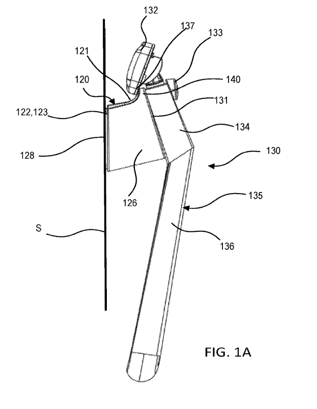
100331 FIGS. 1A-1C illustrate a holder 120 according to an
embodiment, shown holding a
razor 130 to a mounting surface S. FIG. IA is a side view, FIG. 1B is a front
view, and FIG. IC
is a rear view (as seen from a mounting surface S) of the holder 120 and razor
130. The holder
120 can be used to removably hold a variety of different types of articles,
such as the razor 130, to
a mounting surface S. For example, the holder 120 can be used to hold a razor
(such as razor 130)
or other bathroom articles such as a loofa, brush, nail clippers, etc.. The
holder 120 can also be
used to removably hold other types or articles or items, such as kitchen
items, or various tools
CA 03195586 2023-4- 13
WO 2022/119761
PCT/US2021/060954
(e.g., screw drivers, etc.). For example, the holder 120 can be mounted to a
wall (e.g., a bathroom,
wall, shower wall, kitchen wall, garage wall, etc.), to a refrigerator, a tool
box, within an office
system, etc.
[0034] The holder 120 includes a rear plate 122 (also referred to as
"rear portion") having a
first surface 123 (also referred to herein as a "rear surface"), a front plate
124 (also referred to as
a "front portion") having a second surface 125 (also referred to herein as a
"front surface"), and a
base portion 126. In some embodiment, the front plate 124, the base 126 and
the rear plate 122
are each separate components coupled together with, for example, an adhesive
or welding. In
some embodiments, the rear plate 122 can be formed integrally or
monolithically with the base
126 and coupled to the front plate 124, or the front plate 124 can be formed
integrally or
monolithically with the base 126 and be coupled to the rear plate 122. In yet
other embodiments,
the rear plate 122, the front plate 124, and the base 126 can be
monolithically formed.
[0035] The holder 120 can be mounted to the mounting surface S by
any suitable means. For
example, in some embodiments the holder includes an adhesive member 128
disposed on the rear
surface 123. The adhesive member128 can be, for example, a two-sided adhesive
tape that has a
first side that is adhesively attached to the rear surface 123 and a second
opposite side that includes
an adhesive to affix the holder 120 to the mounting surface S. The second side
of the adhesive
member 128 can include an adhesive cover that is removable by a user to expose
the adhesive and
mount the holder 120 to a mounting surface. This arrangement allows for
mounting the holder to
a variety of different materials, such as plastic, shower tiles, glass, stone,
metal, wood, or any other
surface to which the adhesive will stick. In other embodiments, the holder 120
can include a
magnetically attractable rear surface to allow the holder 120 to be mounted to
a magnetic material
(e.g., a ferromagnetic material, such as steel).
[0036] The holder 120 includes a protrusion 140 that extends from a
top surface 121 of the
holder 120. The protrusion 140 functions similar to a hook to allow for a
portion of an article to
be easily coupled and decoupled from the holder 120 as described in more
detail below. The
protrusion 140 can be formed by the base 126 or the base portion and /or the
front plate 124. The
protrusion 140 is configured to engage a portion of an article to be removably
coupled to the holder
120 such as the contact portion 137 of the razor 130. The protrusion 140 can
maintain the article
6
CA 03195586 2023-4- 13
WO 2022/119761
PCT/US2021/060954
(e.g., razor 130) on the holder 120 while providing for easy removal of the
article when desired by
a user. As shown in the front view of the holder 120 in FIG. 3, the front
surface 125 of the holder
120 has a circular shape and is disposed in front of the protrusion 140. The
front surface 125
provides an area against which a second portion of the article can contact
when the contact portion
137 is removably coupled to the protrusion 140. In this embodiment, the front
surface is also a
planar flat surface across a width W and length L (or diameter) of the front
plate 124 (see, e.g.,
FIG. 3). The flat surface and size of the front surface 125 can accommodate a
variety different
articles to be coupled to the holder 120 as described in more detail below. In
addition, the holder
120 can accommodate holding more than one article as described below.
100371 In addition to the protrusion 140, the holder 120 can
optionally include a magnet 142
(see FIG. 5) disposed within the base 126 that can be used to provide a
further point of attachment
for an article to the holder 120. The magnet can be of any suitable size and
strength to produce
the desired magnetic field from the front surface 125. For example, in some
embodiments, the
front surface can be a nonmagnetic material (e.g., plastic) or can be coated
with a nonmagnetic
material (e.g., for durability) and the magnet 142 can be located at a desired
distance below the
front surface 125 such that the front surface remains magnetically
attractable. In other
embodiments, the front plate 124 can be formed at least in part with a
magnetic material rather
than providing a magnet 142 within the base 126 such that the front plate 124
can provide a
magnetic coupling to an article. In some cases, an article to be coupled to
the holder 120 can
include a portion formed of a ferromagnetic material such that the portion
will be magnetically
attracted to the magnet 142 of the holder 120 (or to the front plate 124). The
combination of the
protrusion 140 and the magnet 142 can provide for better fixation of the
article to the holder 120
by providing two coupling points for an article with the holder 120. In some
cases, an article to
be coupled to the holder 120 can include a magnet that can be magnetically
coupled to the magnet
142 of the holder 120. Such an embodiment is described below with respect to
FIG. 7. In addition,
in some situations, the holder 120 can accommodate holding more than one
article. For example,
a first article can be coupled to the protrusion 140 and a second article can
be magnetically coupled
to the holder 120. In some cases, more than one article can be coupled to the
holder 120 via the
protrusion 140. For example, an article, such as a razor, can be coupled to
the holder 120 (via the
protrusion 140 and the magnet 142) and a second article, such as a loofa, can
hang from the
protrusion 140.
7
CA 03195586 2023-4- 13
WO 2022/119761
PCT/US2021/060954
100381 As shown in FIG. 2A, the front plate 124 (and front surface
125) of the holder 120
forms an angle A relative to the back plate 122 such that when an article is
removably coupled to
the holder 120, at least a portion of the article is disposed non-parallel to
the mounting surface S.
This arrangement helps maintain the article coupled to the holder 120 by
providing an additional
point of contact (or attachment via the optional magnet 142). The angled front
surface 125 can
also maintain the position of a lower portion of the article disposed away
from the mounting
surface S. Said another way, a bottom portion of the holder 120 is disposed at
a greater distance
from the mounting surface S than a top portion of the holder 120. For example,
as shown in FIG.
2B, a bottom of the front surface 125 of the holder 120 is disposed at a
distance Di from a bottom
of the rear surface 123, and a top of the front surface 125 is disposed at a
distance D2 from a top
of the rear surface 123. The distance Di is greater than the distance D2 and
corresponds to a width
of the holder 120 at the top of the holder 120, and the distance D2
corresponds to a width of the
holder 120 at a bottom of the holder 120. As also shown in FIG. 2B, a contact
edge 141 of the
protrusion 140 is disposed at a distance D3 from the rear surface 123. The
contact edge 141 is
where an article can engage the protrusion 140 to be held on the holder 120.
The contact edge 141
can provide a surface for engagement with the article (the article can engage
protrusion 140 at any
other suitable surface). In some embodiments, the contact edge 141 has a
portion that includes a
substantially flat surface for engagement with the article. In some cases, the
distance D3 is selected
such that when an article is disposed on the holder 120, the engaging portion
of the article is spaced
a distance from the mounting surface S (e.g., does not contact the mounting
surface). Spacing the
article slightly apart from the mounting surface can prevent scratching or
damage to the mounting
surface S (e.g., from a razor blade as discussed below), can allow for ample
paths to drain water
(e.g., shower water) away from the article (e.g., the razor head 132 discuss
below), and can allow
sufficient clearance to allow the user to easily remove the article from the
protrusion 140.
Moreover, the angled front surface 125 can also accommodate an article (e.g.,
razor) that has an
angled (or bent design), and can keep the lower portion of the article (e.g.,
the bottom portion 136
of the handle 135 discussed below) spaced apart from the mounting surface S
and at least a portion
of the bottom portion 136 of the handle 135 is disposed outside of an envelope
defined by the
holder 120. For example, a portion of the bottom portion 136 of the handle 135
can be disposed
below or beside the holder 120. The angle A can be, for example, between about
5 and 30 degrees
8
CA 03195586 2023-4- 13
WO 2022/119761
PCT/US2021/060954
to accommodate an article (e.g., razor) that has an angled (or bent design).
For example in some
embodiments, the article has an article coupling (or handle) angle of about 5
and 30 degrees.
100391 As shown in FIGS. 1A-1C and 6, the razor 130 includes a
handle 135 and a razor head
132. The handle 135 includes a top portion 134 (also referred to herein as
"first portion) and a
bottom portion 136 (also referred to herein as "second portion"). The razor
130 also includes a
release button 133 that can be used to release the razor head 130 from the
handle 135. In this
embodiment, the top portion 134 is formed with a ferromagnetic material and is
disposed at an
angle (referred to as the coupling angle or handle angle) relative to the
bottom portion 136 to
provide for better ergonomics when using the razor 130. The top portion 134 of
the handle 135
includes a contact surface 131 that can engage the front surface 125 of the
holder 120. In some
embodiments, the contact surface 131 is angled (via the handle angle) to
correspond to the angle
of the front surface of the holder 120. As shown, for example, in FIG. 1A, the
razor 130 can be
coupled to the holder 120 with the razor head 132 disposed over the protrusion
140 with a contact
portion 137 of the razor head 132 engaged with the contact edge 141 of the
protrusion 140 to
prevent the razor 130 from falling downward. As described above, the contact
edge 141 provides
a surface such that the razor head 132 sits upwards against the contact edge
141 (does not angle
downwards), which can help prevent accumulation of water, humidity and rust on
the razor head
132 (see e.g., FIG. 1B). In addition, the contact surface 131 of the top
portion 134 of the handle
135 is engaged with the front surface 125 of the holder 120 such that top
portion 134 of the handle
135 is magnetically coupled to the holder 120 via the magnet 140. In some
embodiments, the
contact surface 131 is a substantially flat, planar surface to provide contact
with an area of the
front surface 125 (as opposed to just a point or line of contact). The razor
130 can be removed
from the holder 120 by grasping the handle 135 and lifting the razor head 132
off of the protrusion
140. Thus, the razor 130 cannot be removed by pulling downward on the razor
130. Moreover,
because in the embodiment, the front surface 125 does not surround the upper
portion 134 of the
handle, the razor 130 can be removed by pulling upward but in any lateral
direction (e.g., upward
at a 45 degree angle to a longitudinal axis of the handle 135). The lower
portion 136 of the handle
135 is unobstructed in all directions to provide for easy access to grasp the
handle 135 to remove
the razor 130 from the holder 120.
9
CA 03195586 2023-4- 13
WO 2022/119761
PCT/US2021/060954
100401 As shown in FIG. 6, when the razor 130 is coupled to the
holder 120, a portion of the
front surface 125 of the holder 120 is unobstructed. Said another way, the
front surface 125 of the
holder 120 has a surface area greater than a surface area of the contact
surface 131 of the top
portion 134 of the handle 135 such that a portion of the front surface 125 is
uncovered when the
razor 130 is coupled to the holder 120. More specifically, as shown in FIG. 6
a right side portion
R and a left side portion L of the front surface 125 are not covered by the
razor 130. This allows
for the razor 130 to be easily placed on the holder 120. In other words, the
size and shape of the
front surface 125 of the holder 120 is not limited to the size and shape of
the razor 130. Thus, the
holder 120 can be used to hold razors with different sizes and shapes and/or
various types of
different articles. In addition, the unobstructed space on the front surface
125 can allow for a
second article to be coupled to the holder 120 in some cases. For example, a
user may couple a
razor to the holder 120 and also a small item such as nail clippers or the
like that can be
magnetically coupled to the front surface 125. Moreover, although the razor
handle 135 is shown
as being centered on the front surface 125 (i.e., the exposed right side
portion R and left side
portion L are substantially equal), because the front surface 125 does not
surround the upper
portion 134 of the handle 135, the razor 130 can be coupled to the holder 120
asymmetrically.
Similarly stated, the design of the front surface 125 allows the razor 130 to
slide to the left or right
(as shown in FIG. 6) while remaining mounted to the holder 120. This can allow
for a larger
exposed surface area of the front surface area.
100411 FIG. 7 illustrates an alternative embodiment of a razor 230
couplable to the holder 120.
In this embodiment, the razor 230 includes a razor head 232, a handle 235 and
a release button
233. The handle 235 includes a top portion 234 (also referred to herein as
"first portion") and a
lower portion 236 (also referred to herein as -second portion") disposed at an
angle relative to the
top portion 234 as described above for razor 130. The razor head 232 can be
coupled to the
protrusion 140 of the holder 120 in the same manner as described above for
razor 130. In this
embodiment, the razor 230 includes a magnet 244 disposed within or coupled to
the top portion
234 of the handle 230. The magnet 244 can have an opposite polarity as the
magnet 142 within
the holder 120 such that the magnet 244 can be magnetically coupled to the
magnet 142 to couple
the razor 230 to the holder 120.
CA 03195586 2023-4- 13
WO 2022/119761
PCT/US2021/060954
[0042] Although the front surface 125 of the holder is shown as
being circular, in other
embodiments, the front surface can have any desired shape (elliptical, square,
rectangular, oval, or
the like). For example, FIGS. 8-10 illustrate another embodiment of a holder
that can be used to
removable couple an article to a mounting surface in the same or similar
manner as described
above for holder 120. The holder 320 includes a rear plate (not shown) (also
referred to as "rear
portion") having a first surface (not shown) (also referred to herein as a
"rear surface"), a front
plate 324 (also referred to as "front portion") having a second surface 325
(also referred to herein
as front surface), and a base portion 326. In some embodiment, the front plate
324, the base 326
and the rear plate are each separate components coupled together with, for
example, an adhesive
or welding. In some embodiments, the rear plate can be formed integrally or
monolithically with
the base 326 and coupled to the front plate 324, or the front plate 324 can be
formed integrally or
monolithically with the base 326 and be coupled to the rear plate. In yet
other embodiments, the
rear plate, the front plate 324, and the base 326 can be monolithically
formed.
[0043] The holder 320 can be mounted to the mounting surface S in
any suitable manner
described herein. In some embodiments, the holder 320 can be mounted with an
adhesive member
(not shown) disposed on the rear surface of the rear plate. The adhesive
member can be for
example, a two-sided adhesive tape that has a first side that is adhesively
attached to the rear
surface and a second opposite side that includes an adhesive to affix the
holder 320 to the mounting
surface S. The second side of the adhesive member can include an adhesive
cover that is
removable by a user to expose the adhesive and mount the holder 320 to a
mounting surface. In
other embodiments, the holder 320 can include a magnetically attractable rear
surface to allow the
holder 320 to be mounted to a magnetic material (e.g., a ferromagnetic
material, such as steel).
[0044] Similar to the holder 120, the holder 320 includes a
protrusion 340 that extends from a
top surface 321 of the holder 320. The protrusion 340 can be formed by the
base 326 or the base
portion and /or the front plate 324. The protrusion 340 is configured to
engage a portion of an
article to be removably coupled to the holder 320 such as the contact portion
337 of the razor 330.
The protrusion 340 can maintain the article (e.g., razor 330) on the holder
320 while providing for
easy removal of the article when desired by a user. As shown in FIG. 8, in
this embodiment, the
front surface 325 of the holder 320 has a square shape. The front surface 325
is also a planar flat
surface across a width and length of the front plate 324. The flat surface and
size of the front
11
CA 03195586 2023-4- 13
WO 2022/119761
PCT/US2021/060954
surface 325 can accommodate a variety different articles to be coupled to the
holder 320 as
described above for holder 120.
100451 In addition to the protrusion 340, the holder 320 can
optionally include a magnet (not
shown) disposed within the base 326 that can be used to provide a further
point of attachment for
an article to the holder 320. In some embodiments, the front plate 324 can be
formed at least in
part with a magnetic material rather than providing a magnet within the base
326 such that the
front plate 324 can provide a magnetic coupling to an article. In some cases,
an article to be
coupled to the holder 320 can include a portion formed of a ferromagnetic
material such that the
portion will be magnetically attracted to the magnet of the holder 320 (or to
the front plate 324).
The combination of the protrusion 340 and the magnet can provide for better
fixation of the article
to the holder 320 by providing two coupling points for an article with the
holder 320. In addition,
in some situations, the holder 320 can accommodate holding more than one
article. For example,
a first article can be coupled to the protrusion 340 and a second article can
be magnetically coupled
to the holder 320. In some cases, more than one article can be coupled to the
holder 320 via the
protrusion 340. For example, an article, such as a razor, can be coupled to
the holder 320 (e.g.,
via the protrusion 340 and the magnet) and a second article, such as a loofa,
can hang from the
protrusion 340.
100461 As shown in FIG. 9, as with the holder 120, the front plate
324 (and front surface 325)
of the holder 320 is disposed at angle relative to the back plate such that
when an article is
removably coupled to the holder 320, at least a portion of the article is
disposed non-parallel to the
mounting surface S to help maintain the article coupled to the holder 320. The
angled front surface
325 can also maintain the position of a lower portion of the article disposed
away from the
mounting surface S. Said another way, a bottom portion of the holder 320 is
disposed at a greater
distance from the mounting surface S than a top portion of the holder 320. A
contact edge 341
(see FIG. 9) of the protrusion 340 is disposed at a distance from the rear
surface of the holder 320
and is where an article can engage the protrusion 340 to be held on the holder
320. The contact
edge 341 can provide a flat surface such that when certain articles are
coupled to the holder 320,
the engaging portion of the article can rest against the flat surface. The
angle can be, for example,
between about 5 and 30 degrees. In some embodiments the angle can correspond
to an article
coupling angle (or bend angle of a handle), which can also be between about 5
and 30 degrees.
12
CA 03195586 2023-4- 13
WO 2022/119761
PCT/US2021/060954
100471 As shown in FIGS. 9 and 10, the razor 330 includes a handle
335 and a razor head 332.
The handle 335 includes a top portion 334 and a bottom portion 336. The razor
330 also includes
a release button 333 that can be used to release the razor head 330 from the
handle 335. In this
embodiment, the top portion 334 is formed with a ferromagnetic material and is
disposed at an
angle relative to the bottom portion 336 to provide for better ergonomics when
using the razor 330.
The top portion 334 of the handle 335 includes a contact surface 331 that can
engage the front
surface 325 of the holder 320. In some embodiments, the contact surface 331
has an angle that
corresponds to the angle of the front surface of the holder 320. As shown, for
example, in FIG. 9,
the razor 330 can be coupled to the holder 320 with the razor head 332
disposed over the protrusion
340 with a contact portion 337 of the razor head 332 engaged with the contact
edge 341 of the
protrusion 340 to prevent the razor 330 from falling downward. As described
above, the contact
edge 341 provides a flat surface such that the razor head 332 can sit upwards
(does not angle
downwards), which can help prevent accumulation of humidity and rust on the
razor head 332
(FIG. 9 illustrates the razor head 332 not fully engaged with the contact edge
for illustration
purposes). In addition, the contact surface 331 of the top portion 334 of the
handle 335 is engaged
with the front surface 325 of the holder 320 such that top portion 334 of the
handle 335 is
magnetically coupled to the holder 320 via the magnet within the holder 320.
The razor 330 can
be removed from the holder 320 by grasping the handle 335 and lifting the
razor head 332 off of
the protrusion 340. The handle 335 is unobstructed in all directions to
provide for easy access to
grasp the handle 335. As shown in FIG. 10, when the razor 330 is couple to the
holder 320, a
portion of the front surface 325 of the holder 320 is unobstructed. Said
another way, the front
surface 325 of the holder 320 has a surface area greater than a surface area
of the contact surface
331 of the top portion 334 of the handle 335 such that a portion of the front
surface 325 is
uncovered when the razor 330 is coupled to the holder 320. As with the holder
120, this allows
for the razor 330 to be easily placed on the holder 320. In other words, the
size and shape of the
front surface 325 of the holder 320 is not limited to the size and shape of
the razor 330. Thus, the
holder 320 can be used to hold razors with different sizes and shapes and/or
various types of
different articles.
100481 FIGS. 11-13 illustrate yet another embodiment of a holder
that can be used to
removably couple an article, such as razor 430 shown in FIGS. 11-13, to a
mounting surface in the
same or similar manner as described above for holder 120. The holder 420 can
include a rear plate
13
CA 03195586 2023-4- 13
WO 2022/119761
PCT/US2021/060954
(not shown) (also referred to as "rear portion") having a first surface (not
shown) (also referred to
herein as a "rear surface"), a front plate 424 (also referred to as "front
portion") having a second
surface 425 (also referred to herein as a first front surface) and a third
surface 427 (also referred
to herein as a second front surface), and a base portion 426. In some
embodiments, the front plate
424, the base 426 and the rear plate are each separate components coupled
together with, for
example, an adhesive or welding. In some embodiments, the rear plate can be
formed integrally
or monolithically with the base 426 and coupled to the front plate 424, or the
front plate 424 can
be formed integrally or monolithically with the base 426 and be coupled to the
rear plate. In yet
other embodiments, the rear plate, the front plate 424, and the base 426 can
be monolithically
formed.
100491 The holder 420 can be mounted to a mounting surface S (see
FIG. 12) in any suitable
manner described herein. In some embodiments, the holder 420 can be mounted
with an adhesive
member (not shown) disposed on the rear surface of the rear plate. The
adhesive member can be
for example, a two-sided adhesive tape that has a first side that is
adhesively attached to the rear
surface and a second opposite side that includes an adhesive to affix the
holder 420 to the mounting
surface S. The second side of the adhesive member can include an adhesive
cover that is
removable by a user to expose the adhesive and mount the holder 420 to a
mounting surface. In
other embodiments, the holder 420 can include a magnetically attractable rear
surface to allow the
holder 420 to be mounted to a magnetic material (e.g., a ferromagnetic
material, such as steel).
100501 In this embodiment, the first front surface 425 is a planar
flat surface that is angled in
a first direction relative to the first surface (i.e., rear surface) of the
rear plate and the second front
surface 427 is a planar flat surface that is angled in a second, opposite
direction relative to the first
surface of the rear plate. Said another way, the first front surface 425 and
the second front surface
427 come together at an apex Ap and are angled in a direction away from each
other. In some
embodiments, the first front surface 425 and the second front surface 427 are
angled to correspond
to an angled contact surface 431 of a top portion 434 (also referred to herein
as "first portion) of
the handle 435, and an angled contact surface 429 of a bottom portion 436
(also referred to herein
as "second portion") of the handle 435 of the razor 430.
14
CA 03195586 2023-4- 13
WO 2022/119761
PCT/US2021/060954
100511 The holder 420 can also include one or more magnets to
magnetically and removably
couple an article (e.g., the razor 430) to the holder 420. For example, as
shown in FIG. 13, the
holder 420 can include a first magnet 442 and a second magnet 443 disposed
within the base 426
that can be used to provide a point of attachment for an article to the holder
420 In some
embodiments, the front plate 424 can be formed at least in part with a
magnetic material rather
than providing a magnet within the base 426 such that the front plate 424 can
provide a magnetic
coupling to an article. In some cases, an article to be coupled to the holder
420 can include a
portion formed of a ferromagnetic material such that the portion will be
magnetically attracted to
one or both of the magnets 442 and 443 of the holder 420 (or to the front
plate 424). In some
embodiments, an article, such as razor 430, can include one or more magnets
that can be
magnetically coupled to the one or more magnets of the holder 420. For
example, as shown in
FIG. 13, a magnet 444 and a magnet 446 are disposed within the handle 435 of
the razor 430. The
magnet 444 and the magnet 446 can each have an opposite polarity as the first
magnet 442 and
second magnet 443 within the holder 420 such that the magnets 444 and 446 can
be magnetically
coupled to the first magnet 442 and the second magnet 443, respectively, to
removably couple the
razor 430 to the holder 420. In addition, in some situations, the holder 420
can accommodate
holding more than one article. For example, a first article can be
magnetically coupled to the
holder 420 via the first magnet 442 and a second article can be magnetically
coupled to the holder
420 via the second magnet 443.
100521 As best shown in FIG. 13, and as described above, the front
plate 424 (and front
surfaces 425 and 427) of the holder 420 are disposed at angles relative to the
back plate such that
when an article is removably coupled to the holder 420, at least a portion of
the article is disposed
non-parallel to the mounting surface S to help maintain the article coupled to
the holder 420.
100531 As shown in FIGS. 11 and 12, the razor 430 includes the
handle 435 and a razor head
432. As described above, the handle 435 includes the top portion 434 and the
bottom portion 436.
The razor 430 also includes a release button 433 that can be used to release
the razor head 430
from the handle 435. Although FIG. 13 shows the handle 430 including two
magnets 444 and 446,
in alternative embodiments, the top portion 434 of the handle 435 can be
formed with a
ferromagnetic material to magnetically couple to the holder 420. The top
portion 434 is disposed
at an angle relative to the bottom portion 436 to provide for better
ergonomics when using the
CA 03195586 2023-4- 13
WO 2022/119761
PCT/US2021/060954
razor 430. The top portion 434 of the handle 435 includes the contact surface
431 that can engage
the first front surface 425 of the holder 420 and the bottom portion 436
includes the contact surface
429 that can engage the second front surface 427 of the holder 420. As shown,
for example, in
FIG. 13, the contact surface 431 of the top portion 434 of the handle 435 is
engaged with the first
front surface 425 of the holder 420 such that the top portion 434 of the
handle 435 is magnetically
coupled to the holder 420 via the magnet 442 within the holder 420 and the
magnet 444 within the
handle 435. And the contact surface 429 of the bottom portion 436 of the
handle 435 is engaged
with the second front surface 427 of the holder 420 such that the bottom
portion 436 of the handle
435 is magnetically coupled to the holder 420 via the magnet 443 within the
holder 420 and the
magnet 446 within the handle 435. When the razor 430 is coupled to the holder
420, the handle
435 is unobstructed in all directions to provide for easy access to grasp the
handle 435 (see e.g.,
FIG. 12). As shown in FIG. 12, when the razor 430 is couple to the holder 420,
a portion of the
first front surface 425 of the holder 420 is unobstructed and a portion of the
second front surface
427 of the holder is unobstructed. Said another way, the first front surface
425 of the holder 420
has a surface area greater than a surface area of the contact surface 431 of
the top portion 434 of
the handle 435 such that a portion of the first front surface 425 is uncovered
when the razor 430 is
coupled to the holder 420. Similarly, the second front surface 427 of the
holder 420 has a surface
area greater than a surface area of the contact surface 429 of the bottom
portion 436 of the handle
435 such that a portion of the second front surface 427 is uncovered when the
razor 430 is coupled
to the holder 420. As with the holder 120, this allows for the razor 430 to be
easily placed on the
holder 420. In other words, the size and shape of the front surface 425 of the
holder 420 is not
limited to the size and shape of the razor 430. Thus, the holder 420 can be
used to hold razors with
different sizes and shapes and/or various types of different articles.
100541 The embodiments of a holder described herein can be provided
in a kit that can include
a holder and an article to be removably mounted on the holder. FIG. 14 is a
schematic illustration
of a kit 500 that includes a package 545 with a holder 520 and an article 530
disposed therein. The
holder 520 can be any of the holders (e.g., 120, 320, 420) described herein
and the article 530 can
be any article that can be coupled to the holder 520. For example, in some
embodiments, the
article 530 is a razor such as the razor 130, 230, 330 or 430 described
herein.
16
CA 03195586 2023-4- 13
WO 2022/119761
PCT/US2021/060954
100551 While various embodiments have been described above, it
should be understood that
they have been presented by way of example only, and not limitation. Where
methods and/or
schematics described above indicate certain events and/or flow patterns
occurring in certain order,
the ordering of certain events and/or operations may be modified. While the
embodiments have
been particularly shown and described, it will be understood that various
changes in form and
details may be made.
100561 Although various embodiments have been described as having
particular features
and/or combinations of components, other embodiments are possible having
various combinations
or subcombinations of any features and/or components from any of the
embodiments described
herein. For example, any of the embodiments of a holder (e.g., 120, 320, 420,
520) can include
only the protrusion (e.g., 140, 340, 440) for coupling an article to the
holder. Although the various
embodiments of a holder are shown only with a razor coupled thereto, as
described herein, the
holders can be used to removably coupled a variety of different types of
articles to a mounting
surface.
100571 Further, although the articles (e.g., razors 130, 230, 330,
430) are shown being coupled
to the holders (120, 320, 420) in a vertical orientation (i.e., longitudinal
axis substantially vertical)
by the flat, upper portion of the handle, in other embodiments, the magnetic
coupling of the holder
can facilitate coupling an article in any suitable orientation. For example,
the handle can be
coupled to the holder at a bottom portion of the handle, attached in a tilted
orientation, attached to
different side of the handle, attached with the razor head facing outward,
etc. In some
embodiments, the bottom portion of the handle can be formed at least in part
with a ferromagnetic
material and can be magnetically coupled to the front surface of the holder.
For example, in some
embodiments, the razor handle can have a ferromagnetic core that allows it to
be magnetically
coupled to the holder at any location along the handle.
17
CA 03195586 2023-4- 13