Note: Descriptions are shown in the official language in which they were submitted.
CA 03195689 2023-03-16
DESCRIPTION
DEVICE AND METHOD FOR CONTROLLABLY CARRYING OUT A
CHEMICAL REACTION
[0001] The invention relates to an apparatus and a method for regulatably
carrying out a chemical reaction in a reactor with at least one heatable
reaction
tube.
PRIOR ART
[0002] In a series of processes in the chemical industry, reactors are used in
which one or more reactants are conducted through heated reaction tubes and
are catalytically or non-catalytically converted there. The heating serves in
particular to overcome the required activation energy for the chemical
reaction
taking place. The reaction can proceed endothermically overall, or
exothermically after overcoming the activation energy. The present invention
relates in particular to strongly endothermic reactions.
[0003] Examples of such processes are steam cracking, different reforming
processes - in particular, steam reforming, dry reforming (carbon dioxide
reforming), mixed reforming processes, processes for dehydrogenating
alkanes, and the like. In steam cracking, the reaction tubes are guided
through
the reactor in the form of tube coils, which have at least one U-bend in the
reactor, whereas, in steam reforming, tubes which typically extend through the
reactor without U-bend are used.
[0004] The invention is suitable for all such processes and embodiments of
reaction tubes. Merely illustratively, reference is made to the articles,
"Ethylene," "Gas Production," and "Propenes," in Ullmann's Encyclopedia of
Industrial Chemistry - for example, the publications of April 15, 2009, DOI:
10.1002/14356007.a10_045.pub2, of December 15, 2006, DOI:
1
Date Recite/Date Received 2023-03-16
CA 03195689 2023-03-16
10.1002/14356007.a12_169.pub2, and of June 15, 2000, DOI:
10.1002/14356007.a22_211.
[0005] The reaction tubes of corresponding reactors are conventionally heated
by using burners. The reaction tubes are guided through a combustion
chamber in which the burners are also arranged.
[0006] However, as described, for example, in DE 10 2015 004 121 Al
(likewise, EP 3 075 704 Al), the demand for synthesis gas and hydrogen,
which are produced without or with reduced local carbon dioxide emissions, is
currently increasing. However, processes in which fired reactors are used
cannot meet this demand due to the combustion of, typically, fossil energy
carriers. Other processes are rejected due to high costs, for example. The
same also applies to the provision of olefins and/or other hydrocarbons by
steam-cracking or dehydrogenating alkanes. In such cases, too, there is a
desire for processes which emit lower amounts of carbon dioxide, at least on-
site.
[0007] Against this background, the cited DE 10 2015 004 121 Al proposes
electrical heating of a reactor for steam reforming, in addition to firing.
Here,
one or more voltage sources are used, which provide(s) a three-phase
alternating voltage on three outer conductors. Each outer conductor is
connected to a reaction tube. A star connection is formed, in which a star
point
is realized by a collector into which the tube lines open and to which the
reaction tubes are conductively connected. In this way, the collector ideally
remains potential-free. In relation to the vertical, the collector is arranged
below
and outside the combustion chamber and preferably extends transversely to
the reactor tubes or along the horizontal. WO 2015/197181 Al likewise
discloses a reactor whose reaction tubes are arranged in a star-point
connection. WO 2020/035575 Al relates to a device for electrically heating a
fluid by means of at least one direct current. DE 10 2011 077 970 Al relates
to
2
Date Recite/Date Received 2023-03-16
CA 03195689 2023-03-16
an apparatus with electrically-conductive heating elements, arranged in a
treatment chamber, for the temperature treatment of corrosive gases.
[0008] During operation of such reactors with electrically-heated reaction
tubes, a change in the electrical properties (resistances) of the reaction
tubes
can occur on the one hand, and changes in the amount and/or the composition
of the reaction products can be desired on the other. The object is therefore
to
be able to adapt the operating conditions of the reactor, or the reaction
parameters of a chemical reaction carried out therewith, to such changes
during operation. Furthermore, there is also the object of being able to adapt
the electrotechnical operating conditions to such changes - in particular,
when
using multiphase AC voltage on the outer conductors.
DISCLOSURE OF THE INVENTION
[0009] This object is achieved by a method and an apparatus for regulatably
carrying out a chemical reaction with the features of the independent claims.
The chemical reaction proceeds in several reaction tubes through which the
process fluid, i.e., the fluid with the reactants (typically a gas or gas
mixture),
is conducted. Tube sections of the reaction tubes are electrically heatable,
wherein the tube sections are connected with power connections to one (or
several) controllable power source or voltage source, at which electrical
currents or voltages for electrical heating are provided. The voltages are
provided as phases of a multiphase AC voltage. According to the invention, the
voltages applied to the power connections can be changed - in particular,
individually. This makes it possible, on the one hand, to keep constant the
heating powers at the tube sections in the event of varying electrical
properties.
A change in the electrical properties can be caused, for example, by inductive
effects due to electromagnetic fields of current-conducting components,
variable temperatures within the reactor, a coke layer formed during
operation,
variable heat demand as a result of changing endothermy/exothermy of the
3
Date Recite/Date Received 2023-03-16
CA 03195689 2023-03-16
reactions, or also manufacturing tolerances or material variations. On the
other
hand, the heating powers can be varied in a targeted manner in order to enable
an adaptation of the composition of the reaction products, which is in
particular
dependent upon the process temperature. Furthermore, the heating power
may also be varied in a targeted manner in order to be able to carry out an
adjustment of the quantity of the reaction products, in the case of a
controlled
composition.
The chemical reaction one of the following: steam cracking, steam reforming,
dry reforming (carbon dioxide reforming), propane dehydrogenation, generally
reactions with hydrocarbons that are carried out at least partially at over
500 'C. In more general terms, the chemical reaction may be a chemical
reaction that proceeds at least partially at a temperature in the range of 200
C
to 1,700 C, and in particular of 300 C to 1,400 C or of 400 C to 1,100 C.
The chemical reaction is preferably a chemical reaction that proceeds at least
partially at a temperature of at least 500 C, more preferably of at least 700
00,
and in particular at least partially in a temperature range of 500 C or 700
C
to 1,100 C. The provided electrical voltages/currents are accordingly
suitable
for providing corresponding heating powers. The reactor and the power source
are likewise configured to carry out chemical reactions at these temperatures
and to provide corresponding heating powers.
[0010] More specifically, the reactor is provided with several reaction tubes
which have a number of electrically heatable tube sections, wherein several
power connections are provided, which are each connected in a current input
area to at least one of the tube sections, wherein at least one connecting
element is provided in a current output area, and each of the tube sections is
connected to a connecting element. Specifically, the method according to the
invention for regulatably carrying out a chemical reaction in a reactor
comprises conducting a process fluid through the several reaction tubes,
providing several variable voltages at the several power connections, wherein
the several voltages are provided as phases of a multiphase AC voltage so
4
Date Recite/Date Received 2023-03-16
CA 03195689 2023-03-16
that the at least one connecting element forms a star point (connecting-
element star point), setting the several voltages, detecting one or more
measured variables, and changing the several set voltages, so that measured
values of the detected measured variables correspond to predetermined
values or value ranges of the measured variables.
[0011] The several provided voltages in this case are in one or more
predetermined voltage ranges, which correspond to heating powers that are
delivered to the electrically heated tube sections and which enable the
chemical reaction in the tube sections, i.e., which heat the latter to a
suitable
temperature.
[0012] Measuring devices, with which these measured variables are detected,
and their arrangement are described in connection with embodiments of the
apparatus according to the invention. The change or control of the voltages at
the power connections takes place as a function of measured values of the
measured variables detected by the measuring devices. This change takes
place such that the measured values correspond to specified values or value
ranges of the measured variables. The wording, "correspond," is to be
understood here to mean that the measured values are equal to or as close as
possible to the specified values or are in the specified value ranges. In
particular, a control loop is thus implemented, wherein the voltages can be
regarded as manipulated variables, and the measured variables can be
regarded as control variables.
[0013] The voltages or the corresponding electrical currents are provided as
alternating voltages or alternating currents. The current input takes place in
the
form of multiphase alternating current into the directly heated reaction tubes
or
the tube sections thereof via M separately connected phases which are
assigned to the power connections (each power connection is thus connected
to one of the phases). The current-conducting reaction tubes or tube sections
which are connected via the power connections to the M phases are,
5
Date Recite/Date Received 2023-03-16
CA 03195689 2023-03-16
advantageously, likewise electrically-conductively connected at a star point
by
the connecting element (in the current output area). The phase number M is in
particular 3, corresponding to the phase number of conventional three-phase
alternating current sources or three-phase alternating current supply grids.
In
principle, however, the present invention is not limited to the use of three
phases, but can also be used with a different, and in particular larger, phase
number - for example, a phase number of 2, 4, 5, 6, 7, or 8. A phase offset is
in particular 360 /M, i.e., in the case of a three-phase alternating current,
1200
.
The advantage of multiphase alternating current is that the currents of the
phases in the star point cancel one another out when the load is substantially
symmetrical, so that no or only little electrical return current to the
voltage
supply or power source occurs. The voltages are thus provided as phases of
a multiphase AC voltage. The power source used for this purpose is,
accordingly, preferably a multiphase alternating current source.
[0014] Preferably, the measured variables comprise one or more of at least
one temperature, at least one current intensity, and/or at least one substance
composition. As a result, the control of the chemical reaction can take place
as
a function of at least one process temperature, at least one heating power
(which is dependent upon the current intensity), or at least one composition
of
the reaction product or the original reactants (i.e., a substance composition
of
the process fluid at the tube inlet or at the tube outlet). Corresponding
desired
values/ranges can thus be achieved.
[0015] The several voltages can be changed in the same way, i.e., they are
changed together, and not independently of one another. Preferably, the
several voltages are changed independently of one another, i.e., each of the
voltages can be individually set, independently of the other voltages.
[0016] Preferably, the one or more measured variables comprise one or both
of: a tube outlet temperature, measured at a tube outlet of the several
reaction
tubes, of the process fluid, and/or a substance composition, measured at a
6
Date Recite/Date Received 2023-03-16
CA 03195689 2023-03-16
tube outlet of the several reaction tubes, of the process fluid. More
preferably,
the several voltages are changed such that the measured tube outlet
temperature and/or the measured substance composition is equal to or as
close as possible to a predetermined tube outlet temperature and/or a
predetermined substance composition, or is within a predetermined value
range. The composition of the reaction product is, in particular, dependent
upon the process temperature (of which the tube outlet temperature is a
measure) with which the chemical reaction proceeds and can therefore be
directly influenced via said process temperature in terms of control
technology.
By changing the voltages and thus the heating power, particular desired
compositions of the reaction product can thus be achieved. If several reaction
tubes are present, the measured variables can accordingly comprise several
tube outlet temperatures and/or several substance compositions at tube
outlets. It is also possible to additionally or alternatively use, as measured
variables, corresponding temperatures or substance compositions measured
at one or more tube inlets, i.e., the measured variables can comprise one or
more tube inlet temperatures and/or one or more tube inlet substance
compositions. Furthermore, it is possible to additionally or alternatively
use, as
measured variables, corresponding temperatures measured at one or more
intermediate positions on one or more reaction tubes, i.e., the measured
variables can comprise one or more intermediate position temperatures on one
or more reaction tubes.
[0017] Preferably, the one or more measured variables comprise one or both
of: two or more tube section temperatures measured at tube sections
connected to various power connections, or two or more power connection
current intensities measured at various power connections. Further preferably,
the several voltages at the various power connections are controlled such that
the measured tube section temperatures correspond to predetermined tube
section temperatures, and/or power outputs, calculated from the current
intensities, at the tube sections connected to the various power connections
correspond to predetermined power outputs. This makes it possible to supply
7
Date Recite/Date Received 2023-03-16
CA 03195689 2023-03-16
heating powers of different strengths to tube sections connected to different
power connections, so that, in particular, different temperatures can also be
set at these different tube sections. Here, an increased return current may
occur via a neutral conductor.
[0018] If different tube sections of a single reaction tube (tube coil) are
connected to different power connections, a desired heating power profile or
temperature profile along the reaction tube can be generated. Preferably, the
method thus comprises setting different voltages at different tube sections of
a
reaction tube, which are connected to different power connections, in order to
supply these tube sections with different heating powers.
[0019] Preferably, the one or more measured variables comprise one or both of:
a neutral conductor current intensity measured at a neutral conductor, or two
or more power connection current intensities measured at various power
connections. Further preferably, the voltages are changed such that the
neutral
conductor current intensity is minimized, and/or a sum, calculated taking into
account the relative phases, of the power connection current intensities is
minimized. In other words, the neutral conductor current intensity or the sum
of the power connection current intensities should correspond as far as
possible to a current intensity value of zero. The second possibility is in
particular advantageous when no neutral conductor is provided. Obviously, this
change in the voltages can take place only within certain voltage ranges which
correspond to heating powers which are suitable or necessary for the chemical
reaction to proceed (the voltages are thus, in particular, not set to zero).
If a
non-symmetrical load through the electrically heated tube sections occurs (for
example, when various tube sections have various electrical resistances), this
can at least partially be compensated for by this embodiment.
[0020] The apparatus according to the invention for regulatably carrying out a
chemical reaction in a process fluid comprises: a reactor having several
reaction tubes, which have a number of electrically heatable tube sections,
8
Date Recite/Date Received 2023-03-16
CA 03195689 2023-03-16
wherein several power connections are provided, which are each connected
in a current input area to at least one of the tube sections, wherein at least
one
connecting element is provided in a current output area, and each of the tube
sections is connected to a connecting element so that the latter forms a star
point (connecting-element star point); at least one controllable power source
(alternating current source) which is configured to provide several variable
voltages at the several power connections, wherein the power source provides
the several voltages as phases of a multiphase alternating voltage; one or
more measuring devices which are configured to detect one or more measured
variables; a control apparatus which is connected to the at least one power
source and to the one or more measuring devices for communication and
which is configured to control the at least one power source as a function of
the one or more measured variables. Here, the tube sections connected to
various phases of the same power source should be connected to the same
connecting element. The change in the voltage can (here, and also in the
above-described method) consist of a change in the (voltage) amplitude itself
(e.g., by means of variable transformers) and/or in a change in an amplitude
averaged over time (in particular, in the root mean square), e.g., by means of
phase angle control or wave packet control (in particular, full wave control).
[0021] The control apparatus is configured to carry out one of the methods
described above or in the further description. In particular, the chemical
reaction is one of the following reactions: steam cracking, steam reforming,
dry reforming, propane dehydrogenation, a reaction with hydrocarbons which
is at least partially carried out at more than 500 C (i.e., the reactor is
configured to carry out one of these chemical reactions).
[0022] Preferably, the one or more measuring devices comprise one or more
of: one or more temperature sensors, which are further preferably configured
to measure temperatures of at least one of the tube sections and/or
temperatures of the process fluid at at least one tube inlet and/or at least
one
tube outlet and/or in at least one tube section, one or more current sensors,
9
Date Recite/Date Received 2023-03-16
CA 03195689 2023-03-16
which are further preferably configured to measure current intensities at at
least one power connection and/or a neutral conductor (which connects the
connecting element to a star point of the power source), or one or more
substance-composition sensors, which are further preferably configured to
measure substance compositions of the process fluid at at least one tube inlet
and/or at least one tube outlet.
[0023] The voltages can be variable together in the same way (i.e., the power
source is configured accordingly), wherein the at least one power source
preferably comprises power controllers, and in particular thyristor power
controllers, by means of which the voltages can be changed. Alternatively, and
more preferably, the voltages can be variable independently of one another,
wherein the at least one power source preferably comprises, for each voltage,
a variable transformer, by means of which the voltages can be changed
independently of one another. Furthermore, alternatively or in addition to
power controllers and/or variable transformers, power electronics may also be
provided, which implement the same functionality, e.g., a so-called flexible
alternating current transmission system (FACTS).
[0024] The one or more measuring devices preferably comprise one or both
of: one or more temperature sensors arranged at tube outlets of the several
reaction tubes, in order to measure one or more temperatures (tube outlet
temperatures) of the process fluid, or one or more substance-composition
sensors arranged at the tube outlets of the several reaction tubes, in order
to
measure one or more substance compositions of the process fluid.
Alternatively or additionally, one or more temperature sensors and/or one or
more substance-composition sensors can likewise be arranged at tube inlets
of the several reaction tubes, in order to measure tube inlet temperatures or
tube inlet substance compositions.
[0025] Preferably, the one or more measuring devices comprise one or both
of: two or more tube-section temperature sensors arranged at tube sections
Date Recite/Date Received 2023-03-16
CA 03195689 2023-03-16
connected to various power connections, or two or more power-connection
current sensors arranged at various power connections. With these measuring
devices, it is possible to measure in particular tube section temperatures
and/or power connection current intensities which may be used in a method
according to the invention as described above. The control apparatus is
accordingly configured to regulate the temperatures of the tube sections
and/or
the heating powers delivered to the tube sections. If the at least one power
source is able to provide the voltages at various power connections
independently of one another, the temperatures of different tube sections or
the heating powers delivered thereto can be regulated independently of one
another, i.e., they can be set to different values / value ranges.
[0026] Preferably, the at least one power source is configured to provide the
voltages independently of one another, and the one or more measuring devices
comprise one or both of: a neutral-conductor current sensor arranged on a
neutral
conductor connected to the connecting element, or several power-connection
current sensors arranged at various power connections. With these sensors, in
particular the neutral conductor current intensity and/or the power connection
current intensities can be measured. Further preferably (as already mentioned
in
connection with the method), the control device is configured to control the
at least
one power source such that voltages with which the neutral conductor current
intensity and/or the sum, calculated taking into account the phases, of the
power
connection current intensities is minimized are provided at the power
connections.
In principle, this establishes equipotentiality between the elements connected
by
the neutral conductor, i.e., between the connecting element and a star point
of the
at least one power source. In particular, it is thereby also possible to the
risk that
outward currents flow into a production system in which the apparatus
according
to the invention is set up and which is electrically-conductively connected
via the
reaction tube at the tube inlet and the tube outlet, and cause electrical
disturbances or associated risks.
11
Date Recite/Date Received 2023-03-16
CA 03195689 2023-03-16
[0027] Within the scope of this application, the terms, "connected,"
"connection," etc., are to be understood in the sense of an electrically-
conductive connection, unless stated otherwise.
[0028] In addition to the electrical heating according to the invention of the
tube
sections, the method or the apparatus may also provide non-electrical heating
of the reaction tube - for example, by fossil fuels. However, the regulation
of
the carrying out of the chemical reaction is achieved according to the
invention
by controlling the voltages applied to the power connections.
[0029] The present invention is described below first with reference to
reaction
tubes and reactors as used for steam cracking or for steam reforming.
However, the invention may also be used in other reactor types. Generally, as
mentioned, the reactor proposed according to the invention can be used for
carrying out all endothermic chemical reactions.
[0030] The invention is explained in more detail below with reference to the
accompanying drawings, which illustrate embodiments of the present
invention.
BRIEF DESCRIPTION OF THE FIGURES
[0031] Figure 1 shows an apparatus according to a preferred embodiment of
the invention;
[0032] Figure 2 shows an apparatus according to a further preferred
embodiment of the invention;
[0033] Figure 3 shows a power source which can be used according to a
preferred embodiment in an apparatus according to the invention;
12
Date Recite/Date Received 2023-03-16
CA 03195689 2023-03-16
[0034] Figure 4 shows a further power source which can be used according to
a preferred embodiment in an apparatus according to the invention; and
[0035] Figure 5 shows a flowchart according to one embodiment of the method
according to the invention.
DETAILED DESCRIPTION OF DRAWINGS
[0036] In the figures, elements corresponding structurally or functionally to
one
another are indicated by identical or similar reference signs and, for the
sake
of clarity, are not explained repeatedly. If components of apparatuses are
explained below, the corresponding explanations also in each case relate to
the methods carried out therewith, and vice versa. The description of the
figures repeatedly refers to alternating current heating.
[0037] Figure 1 schematically illustrates an apparatus for carrying out a
chemical reaction according to one embodiment according to the invention.
[0038] The apparatus comprises a reactor, denoted here by 100, which is
configured to carry out a chemical reaction. For this purpose, it in
particular
has a reaction tube 20 which runs from a tube inlet 22 to a tube outlet 23
through a thermally-insulated reactor vessel 10, wherein a number of tube
sections 24 of the reaction tube 20, which are denoted here by 24 only in two
instances, run in each case between a current input area 11 and a current
output area 12 in the reactor vessel 10. The tube sections 24 form sections of
the reaction tube 20, which are respectively fluidically connected to one
another in the current input area 11 and in the current output area 12 via
curved
portions of the reaction tube - more precisely, first U-bends 26 in the
current
input area 11 and second U-bends 27 in the current output area 12 -so that a
tube coil is formed through which a process fluid can be conducted from the
tube inlet 22 to the tube outlet 23. Here, the reaction tube 20 is fastened by
way of example to a support structure (not shown in greater detail) with
suitable
13
Date Recite/Date Received 2023-03-16
CA 03195689 2023-03-16
suspension means 13, wherein differently designed holding structures for the
reaction tube are in principle also conceivable. It is understood that, here
and
below, several reaction tubes may be provided in each case.
[0039] The material used for the reaction tube(s) is a material with an
electrical
conductivity suitable for electrical heating of the reaction tube(s), e.g.,
heat-
resistant steel alloys, and in particular heat-resistant chromium-nickel-steel
alloys. Such steel alloys can likewise be used for the power connections (via
which the electrical currents are conducted into the reactor vessel) and for
the
connecting element (which is arranged at least partially in the reactor
vessel).
For example, materials with the standard designations, GX40CrNiSi25-20,
GX40NiCrSiNb35-25, GX45NiCrSiNbTi35-25,
GX35CrNiSiNb24-24,
GX45NiCrSi35-25, GX43NiCrWSi35-25-4,
GX10NiCrNb32-20,
GX500rNiSi30-30, G-NiCr28W, G-NiCrCoW, GX45NiCrSiNb45-35,
GX13NiCrNb45-35, GX13NiCrNb37-25, or GX55NiCrWZr33-30-04 according
to DIN EN 10027, Part 1, "Materials," may be used.
[0040] For the electrical heating of the tube sections 24 in the power input
area
11, the tube sections 24 are in each case electrically-conductively connected
or
connectable electrically to phase connections U, V, W of a multiphase power
source 50, i.e., an alternating current source (one power source is explained
below, but also several power sources may be provided; a power source is thus
to be understood in the sense of at least one power source, wherein the
statements apply to all power sources). Switches and the like, as well as the
specific type of connection, are not illustrated. The tube sections 24 are
connected in the power input area 11 to power connections 40, wherein each of
the power connections 40 is respectively assigned one or more tube sections
(two in Figure 1), to which the respective power connection is connected.
[0041] The power source 50 is controllable and configured to provide variable
voltages at the power connections 40. For this purpose, the phase connections
U, V, W of the power source 50 are connected to power connections 40. In the
14
Date Recite/Date Received 2023-03-16
CA 03195689 2023-03-16
embodiment according to Figure 1, the power connections 40 are connected
to the first U-bends 26, which in turn are connected to the tube sections 24,
since U-bends and tube sections form portions of the reaction tube. In this
embodiment, the electrical connection between power connections and tube
sections is thus produced indirectly via the U-bends. However, in deviation
therefrom, a direct connection of the power connections to the tube sections
is
likewise possible; see, for example, the embodiment in Figure 2.
[0042] In the embodiment of the invention illustrated here, the tube sections
24
are electrically-conductively connected to one another in the power output
area
12 by means of a connecting element 42, which is connected to the one or
more reaction tubes 20 and is arranged within the reactor vessel 10. A neutral
conductor 44 and/or a grounding 46 can also be connected thereto. The
neutral conductor 44 is connected to a corresponding connection of the power
source 50 - for example, to a star point of the power source. The current fed
into the tube sections 24 in the current input area 11 is delivered again from
the tube sections 24 in the current output area 12. In terms of circuitry, the
connecting element 42 forms a star point in which, with a suitable supply with
phase-shifted currents (e.g., with a so-called alternating current) by the
voltage
supply 50 and with a symmetrical load by the tube sections 24, the currents or
voltages cancel one another out, so that no current flows via the neutral
conductor 44 to the power source and/or to ground 46 in this case.
[0043] Furthermore, a control apparatus 60 is provided, which is connected to
the power source 50 for communication, e.g., via a control line 52 (however,
any wired or wireless connection may be provided), and which is configured to
control the power source 50, wherein in particular the voltages applied by the
power source 50 to the power connections 40 can be controlled. For this
purpose, the control apparatus 60 is configured to carry out a method
according to the invention. The control apparatus 60 (or the method
implemented by the control apparatus) carries out this control as a function
of
measured variables, which are detected by one or more measuring devices.
Date Recite/Date Received 2023-03-16
CA 03195689 2023-03-16
[0044] In particular, temperature sensors, substance-composition sensors,
and current sensors can be used as measuring devices. In Figure 1, a plurality
of such measuring devices which may be used are shown by way of example.
The measuring devices are connected to the control apparatus 60 via wired or
wireless connections for communication or data transmission, so that
measured variables detected by the measuring devices can be transmitted to
the control apparatus. These connections are not shown in the figure for the
sake of clarity. It should also be pointed out that not all shown measuring
devices have to be provided and that different or additional measuring
devices,
not shown, may also be provided. What measuring devices are provided and
possibly used depends upon which measured variables are required for the
method carried out by the control apparatus.
[0045] Figure 1 shows the following measuring devices: a temperature sensor
62 at the tube outlet 23, which sensor measures the temperature of the
process fluid at the tube outlet; a substance-composition sensor 64 at the
tube
outlet 23, which sensor measures the composition of the process fluid or the
proportion of particular substances in the process fluid at the tube outlet;
temperature sensors 63 (only one provided with a reference sign), which are
arranged on the tube sections 24 in order to measure the temperature of the
respective tube section; a current sensor 66 on the neutral conductor 44, in
order to measure the current intensity of the current flowing in the neutral
conductor (i.e., current between the connecting element 42 and the power
source 50); current sensors 67 at the power connections, in order to measure
currents flowing through the power connections.
[0046] Additionally or alternatively, the following measuring devices (not
shown) may also be provided, for example: a temperature sensor at the tube
inlet 22, which sensor measures the temperature of the process fluid at the
tube inlet; a substance-composition sensor at the tube inlet 22, which sensor
measures the composition of the process fluid or the proportion of particular
16
Date Recite/Date Received 2023-03-16
CA 03195689 2023-03-16
substances in the process fluid at the tube inlet; temperature sensors on
portions of the reaction tube 20 between the tube sections 24, e.g., at the
first
or the second U-bends 26, 27, in order to measure reaction tube temperatures
between the tube sections.
[0047] Figure 2 shows an alternative embodiment of an apparatus according
to the invention. In this embodiment, the reactor 200 has several reaction
tubes
20a, 20b, 20c, each having an electrically heatable tube section 24a, 24b,
24c.
The reaction tubes run through a thermally-insulated reactor vessel 10 and
each has tube inlets 22a, 22b, 22c and tube outlets 23a, 23b, 23c for process
fluids to be processed. For the further configuration, the statements made in
connection with Figure 1 again apply to the extent applicable; in particular,
the
reaction tubes again run through a thermally-insulated reactor vessel 10,
wherein the tube sections are located within the reactor vessel.
[0048] The tube sections 24a, 24b, 24c are connected in a current input area
11 to power connections 40, e.g., by means of sleeves 41. The power
connections 40 are connected to a power source 50 that is controllable and
configured to provide variable voltages at the power connections 40.
[0049] Furthermore, the tube sections 24a, 24b, 24c are conductively
connected in a current output area 12 to a connecting element 42, so that the
tube sections are conductively connected to one another there. The
connecting element 42 can be connected again to a ground 46 and/or a neutral
conductor 44, wherein the neutral conductor 42 is connected to a
corresponding connection of the power source 50.
[0050] Likewise, a control apparatus 60 is provided, which is connected to the
power source 50 in a wired or wireless manner for communication (e.g., via a
control line 52), so that the control apparatus 60 can control the power
source
50. Measured variables detected by measuring devices - in particular,
17
Date Recite/Date Received 2023-03-16
CA 03195689 2023-03-16
temperature sensors, substance-composition sensors, and current sensors -
are again used for the control.
[0051] By way of example, Figure 2 again shows several measuring devices,
which can be used to detect corresponding measured variables. The
measuring devices are connected to the control apparatus 60 via wired or
wireless connections for communication or data transmission, so that
measured variables detected by the measuring devices can be transmitted to
the control apparatus. These connections are not shown in the figure for the
sake of clarity. It should also be pointed out that not all shown measuring
devices have to be provided and that additional measuring devices, not shown,
may also be provided. What measuring devices are provided and possibly
used depends upon which measured variables are required for the method
carried out by the control apparatus.
[0052] Figure 2 shows the following measuring devices: temperature sensors
62a, 62b, 62b at the tube outlets 23a, 23b, 23c, which sensors measure the
temperature of the process fluids at the tube outlets; substance-composition
sensors 64a, 64b, 64c at the tube outlets 23a, 23b, 23c, which sensors measure
compositions of the process fluids or the proportion of particular substances
in the
process fluids at the tube outlets; temperature sensors 63a, 63h, 63c, which
are
arranged on the tube sections 24a, 24b, 24c, in order to measure the
temperature
of the respective tube section; a current sensor 66 on the neutral conductor
44, in
order to measure the current intensity of the current flowing in the neutral
conductor (i.e., current between the connecting element 42 and the power
source
50); current sensors 67 at the power connections 40, in order to measure
currents
flowing through the power connections.
[0053] Additionally or alternatively, the following measuring devices (not
shown) may also be provided, for example: temperature sensors at the tube
inlets 22a, 22b, 22c, which sensors measure temperatures of process fluids at
the tube inlets; substance-composition sensors at the tube inlets 22a, 22b,
18
Date Recite/Date Received 2023-03-16
CA 03195689 2023-03-16
22c, which measure the composition of the process fluids or the proportion of
particular substances in the process fluids at the tube inlets.
[0054] Figures 1 and 2 show specific embodiments of apparatuses according
to the invention, in which in particular a specific embodiment of the reaction
tubes and the connection thereof to a power source are shown in each case.
However, it should be emphasized that, within the scope of the claims (both in
the apparatus claims and in the method claims), other embodiments of the
reaction tubes and their electrical connection to one power source, or also to
several power sources, are possible. In particular, it is possible for the
reactor
to comprise several tube coils (similarly to Figure 1), wherein the latter
are, for
example, arranged in the manner of a stack, parallel to and at a distance from
one another (starting from Figure 1, perpendicularly to the drawing plane).
[0055] This set of tube coils (in the stack) can be subdivided into subsets
which
are each assigned to a power source, wherein also a subdivision in which a
subset contains only one tube coil or a subdivision in which a (single) subset
contains all the tube coils are possible. The connections are then each
assigned to a subset, the tube sections of the tube coils of the subset are
connected to one of the connections assigned to the subset, and each subset
may be assigned to a power source whose phases are connected to the
connections assigned to the subset. For each subset, a connecting element is
then likewise provided, which connects the tube sections of the subset,
wherein it is also possible for one connecting element to be provided for each
individual tube coil.
[0056] Likewise, a one-to-one relationship between connections and tube coils
can exist (in particular, in the case of a U-shaped tube coil), i.e., all tube
sections of a tube coil are respectively connected to the same connection.
Since the connections are each connected to various phases or voltages, the
number of tube coils then corresponds to the number of various voltages or a
19
Date Recite/Date Received 2023-03-16
CA 03195689 2023-03-16
multiple thereof. The one or more connecting elements then each connect tube
sections of various tube coils.
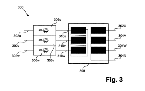
[0057] Figure 3 represents a possible embodiment of a controllable power
source 300, which uses thyristor power controllers for power control. The
controllable power source has connections on the input side to a power supply,
e.g., a power supply network, wherein an input 302u, 302v, 302w is provided
for each phase (here, for example, 3) of an AC voltage supply. Relatively high
voltages are applied to the inputs - typically, several hundred to several
thousand volts, e.g., 400 V, 690 V, or 1.2 kV. On the output side, the power
source has outputs 304U, 304V, 304W, which are connected to power
connections of a regulatable reactor, e.g., to the power connections 40 of one
of the reactors shown in Figures 1 or 2. Furthermore, a connection 304N for a
neutral conductor is provided on the output side.
[0058] The power source 300 has power controllers 306u, 306v, 306w - here,
thyristor power controllers - by means of which the voltages applied to the
inputs can be interrupted or can be passed through to a high-current
transformer 308 via lines 310u, 310v, 310w. The multiphase high-current
transformer 308 - here, for example, in a delta/star configuration, wherein
the
connection 304N for a neutral conductor is connected to the star point -
transforms the relatively high voltages applied between the inputs into lower
voltages with simultaneously higher current intensities which are suitable for
feeding into the tube sections. The output voltage is preferably in a range of
less than 300 V, more preferably less than or equal to 150 V, even more
preferably less than or equal to 100 V, and most preferably less than or equal
to 50 V.
[0059] By correspondingly controlling the power controllers 306u, 306v, 306w,
i.e., by alternately interrupting and passing through (by means of the
thyristors)
the voltages applied to the inputs, to the high-current transformer, the power
delivered on the output side can be controlled. For this purpose, a pulse
width
Date Recite/Date Received 2023-03-16
CA 03195689 2023-03-16
modulation (PWM) can be used during actuation. Preferably, only full waves of
the alternating voltages applied on the input side are passed through by the
power controllers, i.e., a so-called pulse group operation or full-wave pulse
is
provided, in which complete sinusoidal waves are switched through. This
serves to reduce harmonics and the associated filter outlay for maintaining
the
voltage quality on the supply network.
[0060] The power controllers are actuated via control lines (not shown), to
which are applied control signals based upon voltage requirements specified
externally, i.e., by the control apparatus 60.
[0061] Figure 4 shows another possible embodiment of a controllable power
source 400, which uses variable transformers for power control and which
allows a mutually-independent change in the voltages at the outputs. The
controllable power source 400 has connections on the input side to a power
supply, e.g., a power supply network, wherein an input 402u, 402v, 402w is
provided for each phase (here, for example, 3) of an AC voltage supply.
Accordingly, relatively high voltages are applied to the inputs - typically,
several
hundred to several thousand volts, e.g., 400 V, 690 V, or 1.2 kV. On the
output
side, the power source has outputs 404U, 404V, 404W, which are connected
to power connections of a regulatable reactor, e.g., to the power connections
40 of one of the reactors shown in Figures 1 or 2. Furthermore, a connection
404N for a neutral conductor is provided on the output side.
[0062] The power source 400 comprises variable transformers 406u, 406v,
406w, i.e., transformers whose output-side voltage is controllable in
particular
regions or even completely, i.e., from 0-100%. The output voltages of the
variable transformers, which are relatively high in the case of a
correspondingly
requested heating power, are transformed by single-phase high-current
transformers 408u, 408v, 408w, which are connected to the variable
transformers via lines 410u, 410v, 410w, into lower voltages or currents with
higher current intensity and are provided by the high-current transformers at
21
Date Recite/Date Received 2023-03-16
CA 03195689 2023-03-16
the outputs 404U, 404V, 404W. The output voltages are preferably in a range
of less than 300 V, more preferably less than or equal to 150 V, even more
preferably less than or equal to 100 V, and most preferably less than or equal
to 50 V. The connection 404N for a neutral conductor is connected here to a
corresponding connection on each of the high-current transformers.
[0063] Here, the output powers can be controlled independently of the other
output powers for each of the outputs 404U, 404V, 404W, in that the associated
variable transformer 406u, 406v, 406w is actuated accordingly, i.e., in that
the
output voltage at the respective variable transformer is set accordingly. The
power controllers are actuated again via control lines (not shown), to which
are
applied control signals based upon voltage requirements specified externally,
i.e., by the control apparatus 60.
[0064] The use of a power source with variable transformers has further
advantages in addition to the independent controllability of each individual
voltage. First, in addition to harmonics, low-frequency voltage oscillations
can
also be avoided (which, in the embodiment with power controllers can occur
due to switching on/off processes). These low-frequency oscillations are
disadvantageous, since they can be in the range of resonance frequencies of
the reaction tubes on which electromagnetic forces act. Furthermore, when
using appropriate variable transformers, the voltages can be controlled from
0-100%, which is useful, for example, during startup/shutdown or during load
changes of the reactor; switch-on currents can likewise be limited thereby.
[0065] Figure 5 represents the basic sequence of a method according to the
invention, wherein an apparatus according to the invention, as described, for
example, in Figure 1 or Figure 2, is preferably used, wherein the control
apparatus is configured to carry out the method. During the method, a process
fluid to be heated or several process fluids to be heated are conducted
through
one or more reaction tubes of the reactor (step 502).
22
Date Recite/Date Received 2023-03-16
CA 03195689 2023-03-16
[0066] In step 504, voltages or currents are first provided at power
connections
of the reactor. This is done by a controllable power source. In step 506, the
voltages are set to particular voltage values, e.g., by a control apparatus
connected to and controlling the power source.
[0067] In step 508, one or more measured values are detected, i.e., measured
values (for example, temperature values, current intensity values) of the
measured variables (for example, temperature, current intensity) are detected.
The measured values are thus the values of the measured variables at a
respective measurement time point. For this purpose, as described above
(Figures 1, 2), measuring devices are provided.
[0068] In step 510, the detected measured values are compared with specified
values or target values of the corresponding measured variables. It is
determined whether the detected measured values correspond to the
predetermined values of the measured variables. Here, "correspond" is to be
understood in a general sense, i.e., that the detected measured values are
equal to or come as close as possible to the predetermined values or are also
in particular ranges around the predetermined values.
[0069] If the detected measured values correspond to the predetermined
values of the measured variables, the measured variables are measured
again, i.e., the measured values are detected again; the method thus returns
to step 508 (arrow 512). The voltages then remain unchanged. If, on the other
hand, the detected measured values do not correspond to the predetermined
values of the measured variables, the voltages are set anew, i.e., the method
returns to step 506 (arrow 514). The voltages and thus the heating powers in
the various associated tube sections are thus changed, such that the values
of the measured variables change and subsequently, or after several setting
steps, correspond to the predetermined values of the measured variables. For
this purpose, for example, a corresponding control algorithm is provided in
the
control apparatus.
23
Date Recite/Date Received 2023-03-16