Note: Descriptions are shown in the official language in which they were submitted.
WO 2022/115462
PCT/US2021/060586
FLOOR PANEL AND METHODS FOR MANUFACTURING FLOOR
PANELS
CROSS-REFERENCE TO RELATED APPLICATION
This application claims priority to U.S. Provisional Patent Application
Serial No. 63/117,802, which was filed on November 24, 2020, the disclosure
of which is incorporated herein by reference in its entirety.
TECHNICAL FIELD
This invention relates to a floor panel, as well as to a method for
manufacturing floor panels.
BACKGROUND
More particularly, the invention relates to decorative panels, such as
floor panels, which comprise a top layer or decorative layer on the basis of
wood. Such panels are widely known as such, for example, from
WO 2010/122514. In the case of floor panels, it concerns ready-to-lay,
prefabricated or composed parquet, in English also indicated as "Engineered
Wood Parquet", or about veneer parquet. The present invention is directed in
particular to floor panels for veneer parquet, namely, to floor panels with a
wooden top layer with a thickness of 1 millimeter or less.
Floor panels for veneer parquet are described, for example, in
US 5,755,068 and usually comprise at least a substrate and a glued thereon
wood veneer of less than 2 millimeters. According to the EN 13489 standard,
panels with a wooden top layer of 2.5 millimeters and more can be called multi-
layered parquet or "multilayer parquet" and are not considered veneer
parquet. With panels for veneer parquet, a wood-based backing layer can be
glued to the underside of the substrate as well. The wood layer situated at
the
upper side functions as a top and decorative layer and mostly is realized from
hardwood. It may in fact be treated further at its upper side, for example, in
order to exert an influence on the appearance thereof and/or in order to
improve the surface quality thereof, for example, via coloring, applying a
wear-
CA 03195946 2023-4- 17
WO 2022/115462
PCT/US2021/060586
resistant and/or waterproof lacquer, and so on. The wood-based backing layer
mostly consists of a unitary thin layer of a cheap and mostly soft wood
species.
Such veneer parquetry panels are sensitive to impressions by impact and can
be scratch-sensitive. Due to their insufficient mechanical features, soft wood
species are unusable as top layer for such panels. At the end-side edges of
the veneer, there is a risk of penetration of moisture, and circular spots may
show on the veneer surface.
From DE 102 45 915, it is known, for the top layer of veneer parquet,
to glue a wood veneer impregnated with thermosetting resin on an MDF or
HDF substrate, printing it and finishing it with a wear-resistant lacquer. For
the
resin, use is made of phenolic resin or melamine resin. US 2006/070,325 and
US 2005/136,234 describe a method wherein a wooden top layer of 2
millimeters or more is glued under pressure on an MDF/HDF substrate,
wherein a certain impregnation of the applied glue in the wooden top layer is
obtained. DE 20 2013 012 020 U1 and WO 2015/078434 describe a method
wherein a wooden veneer layer with a thickness between 0.6 mm and 1.2 mm
is pressed, via an intermediate resin layer, on an MDF/HDF substrate in a hot
press. The intermediate resin layer can comprise a thermosetting resin. The
panels known from the aforementioned documents still show a limited wear
resistance.
From WO 2017/009744 and WO 2017/001976, it is known that veneers
of soft wood species can be compressed such that they become suitable as a
decorative top layer for a veneer parquet. From WO 2017/001976,
WO 2015/105456 and WO 2017/188883 it is further known to apply aluminum
oxide particles in order to increase the wear resistance of the panels.
According to W'456 and WO'883, a permeation of a colored mixture of glue
and hard particles towards the surface of the veneer is intended, namely
through pores, cracks and knots, by which pores and defects are filled up or
repaired. In that the glue mixture colors the surface at least at the location
of
the pores and defects, the techniques of W'456 and WO'883 are suited
primarily for manufacturing rather rustic veneer parquets.
2
CA 03195946 2023-4- 17
WO 2022/115462
PCT/US2021/060586
From WO 2019/135141 it is known to provide large hard particles
underneath the veneer, such that in the finished products these particles
penetrate the veneer from the bottom side. An increased abrasion resistance
is obtained.
SUMMARY
The present invention primarily aims at an alternative panel for veneer
parquet, wherein according to various preferred embodiments solutions are
offered for the problems with the floor panels of the state of the art.
To this aim, in accordance with a first independent aspect, the present
invention relates to a floor panel with a substrate and a provided thereon
decorative layer of wood veneer with a thickness of 1 millimeter or less,
wherein a lacquer layer, preferably comprising transparent or translucent
surface material is provided, on said wood veneer, with as a characteristic
that
said lacquer layer comprises hard particles and extends from the upper
surface of the wood veneer at least up to a side edge of said wood veneer,
such that said side edge is at least partially covered by said lacquer. The
lacquer layer brings an increased wear and/or scratch resistance to the floor
panel, while its presence on the side edge of the wood veneer increases the
water resistance of the wood veneer. The lacquer has the ability of sealing
the
edges of the wood veneer. This is especially advantageous when the relevant
veneer edge is obtained by a cross cut through the veneer. Such cross cut
may comprise open wood grain vessels. These vessels tend to suck in water
or other liquids due to capillary effects, which then again leads to
discoloration
of the veneer. The portion of the lacquer on the side edge of the veneer may
seal such vessels.
Preferably the entire relevant side edge of the veneer is covered by
said portion of the lacquer. Preferably at least two opposite side edges of
the
veneer are at least partially covered, or preferably entirely covered by said
lacquer. Preferably at least the two cross cut edges of the veneer are
partially
or wholly covered. Of course, it is not excluded that the veneer would be
covered at all side edges by said lacquer.
3
CA 03195946 2023-4- 17
WO 2022/115462
PCT/US2021/060586
Preferably, said lacquer layer comprises in itself at least two sublayers,
wherein preferably at least the uppermost or only the uppermost of said at
least two sublayers at least partially covers said side edge. This preferred
embodiment allows for a fluent application and/or a minimized interference
with the adjoining of floor panels in a floor covering.
Preferably the uppermost of said at least two sublayers is thinner than
the other of said two sublayers, wherein preferably only said uppermost of
said at least two sublayers is available on said side edge of said veneer. In
accordance with this embodiment a good adjoining of floor panels can be
maintained.
Preferably said hard particles comprise first hard particles in said
uppermost sublayer, and second hard particles in the other of said two
sublayers. In accordance with a variant, said uppermost sublayer comprises
said hard particles, while the other of said two sublayers is free from hard
particles. The particles or first particles contained in said uppermost
sublayer
have a more immediate effect on abrasion and scratches, while the particles,
or second particles, potentially contained in the other sublayer come into
play
after some wear has already taken place, i.e. when the uppermost layer has
been worn out.
Preferably, said second hard particles have an average particle size
that is larger than the average particle size of said first hard particles,
wherein
preferably the average particle size of said second hard particles is at least
2
times larger than the average particle size or said first hard particles. With
this
embodiment, the smaller particles, that are more effective for scratch
resistance, are available more immediately than the larger particles that are
more effective for abrasion resistance.
Preferably, said first hard particles have an average particle size of 30
micron or below, preferably of 15 micron or below. An average particle size of
5 micron or of 1 micron and below are not excluded. Preferably, said second
hard particles have an average particle size of 120 micron or below,
preferably
4
CA 03195946 2023-4- 17
WO 2022/115462
PCT/US2021/060586
of 85 micron or below, but preferably above 30 micron. In selecting the second
hard particles in this range, the second hard particles may stay effectively
invisible while delivering a high abrasion resistance.
Preferably, said decorative layer is provided on the substrate by a glue
layer which is situated between the substrate and the decorative layer,
wherein said glue layer preferably comprises third hard particles. Preferably
said third hard particles have an average particle size which is at least one
third of the thickness of the wood veneer, and still better with an average
particle size which is at least one half or two thirds of the thickness of the
wood
veneer. It is clear that the thickness of the wood veneer herein relates to
the
thickness in the floor panel itself and not the thickness of the wood veneer
before it is provided on the floor panel. As known from the state of the art,
for
example, from WO 2017/009744 and WO 2017/001976, namely a
considerable compression of the wood veneer may be created when gluing or
pressing it onto the substrate. The large hard particles which are applied
within
the scope of the present invention can limit the known compression of the
wood veneer. This is advantageous from an economic point of view, as the
client expects a certain thickness of the veneer.
To the person skilled in the art of the technical field, it is clear that the
average particle size is determined via the technique of sieve analysis. Said
sieve analysis uses a stack of sieves, wherein these sieves comprise raster
openings of different size. Of course, the raster openings have to be chosen
in accordance with the precision which is desired, and in function of the
estimated particle size. Preferably, the stack can be composed by diminishing
the size of the openings of the raster of the sieves from top to bottom. The
sieve analysis is performed on dry particles. The sieve analysis can be
performed either manually or by machine. At the end of the sieve analysis,
from an initial sample, on each sieve a fraction of particles remains, with a
size
that is larger than the raster opening of the respective sieve and smaller
than
the raster opening of the preceding sieve. The weight of the remaining
particle
fraction is measured per sieve. The result of said sieve analysis thus is a
5
CA 03195946 2023-4- 17
WO 2022/115462
PCT/US2021/060586
weight distribution, wherein for each sieve, namely for the range of particle
sizes corresponding to the raster openings between two adjacent sieves, the
absolute weight in particles is registered.
The average particle size is calculated as the volumetric average
particle size by recalculating the absolute weight of each range of particle
sizes, as obtained from the aforementioned sieve analysis, to an absolute
volume of each particle size on the basis of the density of the particles.
From
the absolute volume of a range of particle sizes, on the basis of the volume
of
one particle with the respective particle size (the average between the lower
limit and the upper limit of the respective range) the number of particles
with
the respective particle size is calculated. On the basis of the calculated
number of particles and the absolute volume for each particle size, the
average particle volume of the respective sample is calculated. From the
respective average particle volume, with the fictitious assumption that the
particles are spherical, the volumetric average particle size is calculated.
In the cases where the third hard particles show an average particle
size which is at least one third of the thickness of the wood veneer, it is
guaranteed that these particles can penetrate to a not negligible extent into
the underside of the veneer, by which a reliable barrier against excessive
wear
can be created. So, for example, the third hard particles, or at least the
most
important fraction thereof, for example, more than 30% by weight or more than
50% by weight of the present particles, can penetrate into the veneer from the
underside over a distance of at least 20% of the thickness thereof.
Preferably, the third hard particles, or anyhow at least 30% by weight
of the third hard particles which are present, penetrate from the underside
into
the veneer. Preferably, these particles penetrate into the veneer from on the
underside over a distance of at least 50% of the thickness thereof, or even of
at least 75% of the thickness thereof.
Preferably, at least 40 particles per square centimeter, and still better
at least 100 particles per square centimeter, penetrate into the veneer over a
6
CA 03195946 2023-4- 17
WO 2022/115462
PCT/US2021/060586
distance of at least 20% of the thickness thereof, and still better of at
least
50% of the thickness thereof.
Preferably, less than 1 particle per square centimeter completely
penetrate through the veneer, such that always an undisturbed or hardly
disturbed veneer layer is maintained, wherein knots, cracks and other defects
in the veneer are not taken into consideration.
Preferably, the floor panel of the invention comprises more than 30
grams per square meter of third hard particles underneath the veneer, which
then, in accordance with the invention, show an average particle size of more
than a third of the thickness of the veneer. Preferably, the content of third
hard
particles underneath the veneer is between 35 and 70 grams per square
meter, wherein 40 to 50 grams per square meter is the most interesting from
several points of view.
Preferably, the present glue of the glue layer also penetrates into the
veneer from the underside, however, preferably nowhere further than over a
distance which is smaller than 50% of the thickness thereof, and still better
smaller than 20% of the thickness thereof. In this manner, it is obtained that
when, due to wear of the veneer floor, the barrier of the penetrating hard
particles is reached, the glue is not visible yet. Glue often leads to a
discoloration of the veneer. By the present preferred embodiment, it is
avoided
that thus discoloration would be visible at an early stage. A discoloration
which
is visible too early would lead to a premature wear inacceptable to the user.
Preferably, the aforementioned substrate, at the surface where the
decorative layer is situated, has a density of more than 900 kilograms per
cubic meter. In this manner, it is obtained that the third hard particles
preferentially penetrate into the veneer and not into the substrate.
Preferably, the aforementioned substrate is a wood fiberboard, more
particularly of the type MDF (Medium Density Fiberboard) or HDF (High
Density Fiberboard). However, it is not excluded that other board materials
are employed for the substrate. Preferably, these board materials show a high
7
CA 03195946 2023-4- 17
WO 2022/115462
PCT/US2021/060586
density at least at their surface. So, for example, a mineral-bonded board can
be chosen for, such as a cement fiberboard, a magnesite board or the like.
According to another possibility, with similar effect, a plastic board based
on
rigid PVC (polyvinylchloride) or having a rigid PVC layer at its surface can
be
opted for. The rigid PVC may for example be PVC with less than 5phr
plasticizer. Such board or layer may contain fillers such as calciumcarbonate
and/or sand, in a content of 40 to 85 percent by weight.
Preferably, the aforementioned glue layer is layer on the basis of
thermosetting resin, preferably ureum-based resin, such as
ureumformaldehyde resin. According to a variant melamine-based or phenol-
based resin can be used. According to another variant mixtures of the
aforementioned resins can be used, such as ureumformaldehyde resin with
an addition of melamine. In the latter case a more moisture resistant resin is
obtained. With a thermosetting resin, a very reliable connection between the
substrate and the wood veneer can be obtained, wherein the third hard
particles are well embedded. Preferably, the resin is hardened by a press
treatment, for example, with a pressure of 10 bar or more, or even of 20 bar
or more, such that by this press treatment the penetration of the third hard
particles into the underside of the veneer can be obtained as well. As already
mentioned, the aforementioned wood veneer preferably is at least partially
impregnated by the aforementioned thermosetting resin. The wood veneer
shows such impregnation preferably from the underside up to a certain depth
in the wood veneer, wherein this depth is smaller than 50% of the thickness
of the wood veneer and preferably is smaller than the average penetration
depth of the hard particles.
A choice of a glue layer of melamine-based resin is advantageous in
view of limiting the risk of coloring the veneer. Other thermosetting resins,
such as ureum formaldehyde-based resins, lignosulfonate-based resins or
furane-based resins have a brownish color, which can darken the natural color
of the veneer, although this is not excluded in the scope of the invention.
Certainly when the impregnation of the glue on the underside of the veneer is
8
CA 03195946 2023-4- 17
WO 2022/115462
PCT/US2021/060586
limited, it may be economically advantageous to still employ these light-
colored resins.
According to variants, it is not excluded that the glue layer comprises a
glue on the basis of polyurethane, hot-melt adhesive ("hotmelt") or polyvinyl
acetate ("PVAc").
Preferably, the aforementioned glue layer, preferably a glue layer on
the basis of a thermosetting resin, extends uninterruptedly underneath the
entire wood veneer. According to this embodiment, it is avoided that due to
expansion of the wood veneer bubbles are created in the surface of the floor
panel, and it is obtained that the aforementioned third hard particles
everywhere are bonded at least to a certain extent in the glue layer.
Preferably, the aforementioned wood veneer at the upper side of the
floor panel has a thickness between 0.3 and 1 millimeter, preferably between
0.45 and 0.7 millimeter, for example approximately 0.6 millimeters. The
potential third hard particles may then have an average particle size of 100
microns or more, and preferably smaller than 1000 microns, or still better
between 300 and 1000 microns, but preferably not larger than the thickness
of the veneer. To the person skilled in the art, it is clear that the average
particle size is measured by sieve analysis.
The material of the aforementioned hard particles preferably has a
hardness of 7 or more on the Mohs scale and/or is preferably chosen from the
list of aluminum oxide, titanium carbide, silicon carbide and silicon oxide.
In
the most preferred embodiment, hard particles of aluminum oxide or so-called
corundum are applied.
Preferably, hard particles of the angular type (angular format) are
employed.
In accordance with the invention, said decorative layer comprises a
lacquer with transparent or translucent surface material at the surface.
According to a particular possibility, the transparent or translucent surface
9
CA 03195946 2023-4- 17
WO 2022/115462
PCT/US2021/060586
material is obtained at least on the basis of a polyurethane-based and/or
acrylate-based lacquer, for example, a lacquer with at least 25 percent by
weight, or still better at least 50 percent by weight of acrylates chosen from
the list consisting of polyurethane acrylates, polyester acrylates and/or
epoxide acrylates. Preferably, it relates to a lacquer which is cured with UV
radiation, electron beam or excimer radiation. This may relate, for example,
to
surface material which is provided by an inert coating-system. Such systems
are known, for example, from EP 2 805 778. Herein, a lacquer is cured by
radiation, for example, UV radiation, through a transparent press element, for
example, through a transparent press belt or press foil. Preferably, with the
surface material a matte surface is obtained, namely a surface with a gloss
degree of 10 or less, as measured according to DIN 67530. The gloss degree
of the surface can be obtained, for example, by an excimer-cured lacquer
layer. With excimer-cured lacquer layers, the gloss degree even can be
adjusted by setting the energy impinging on the surface material to be cured.
According to a variant, the gloss degree of the surface can also be obtained
by an inert coating-system, wherein the structure of the applied press
element,
preferably a press foil, determines the gloss degree. Of course, it is also
possible to obtain a glossy surface with the surface material, for example, a
surface with a gloss degree of 20 or more, as measured according to DIN
67530. Preferably, the transparent surface material contains 15 to 30 percent
by weight of hard particles, such as particles of corundum (Aluminum oxide)
and/or silica (Silicon oxide). Herein, this may relate to particles with an
average particle size of 50 micrometers or smaller, or even of 10 micrometers
or smaller, wherein it is not excluded that particles might be used having an
average particle size situated between 100 nanometers and 1 micrometer. To
the person skilled in the art, it is clear that the average particle size is
measured by sieve analysis. Such particles can increase the scratch
resistance of the surface. The thickness of the surface material preferably is
0.05 millimeters or less. Preferably, the surface material follows a possible
relief present at the surface of the wood veneer, for example, at least
possibly
present lower edges and preferably also at least a portion of the wood pore
CA 03195946 2023-4- 17
WO 2022/115462
PCT/US2021/060586
structure of the veneer. Preferably, the surface material extends layer-shaped
over at least 80 percent of the surface of the veneer layer, and still better
over
the entire or almost the entire surface thereof.
Preferably, said floor panel comprises 5 to 50 grams per square meter,
and even better 5 to 25 grams per square meter of hard particles above the
wood veneer, wherein preferably said first hard particles are available in an
amount smaller than said second hard particles.
The veneer surface may have an oil finish wherein the oil penetrates
into the veneer to a certain extent. The lacquer layer which in accordance
with
the invention covers at least a side edge of the wood veneer, is in such case
present on top of the oil finished veneer.
The invention preferably is applied with floor panels which can be
applied for composing a floating floor covering. Preferably, the floor panels
to
this aim, on at least two opposite edges, are provided with coupling
structure(s) allowing that two of such floor panels can be coupled to each
other
in a vertical direction perpendicular to the plane of the coupled panels and
in
a horizontal direction in this plane and perpendicular to the respective edge.
Such coupling structure(s) are known as such, for example, from
WO 97/47834. According to an important first possibility hereof, the coupling
structure(s) at two opposite edges preferably are realized substantially as a
tongue and a groove with locking parts which prevent the moving apart of the
tongue and groove. Such locking parts can consist, for example, of an
upwardly projecting locking element at the lower groove lip, wherein this
locking element borders a recess in the lower groove lip, and a protrusion,
cooperating with this locking part, at the underside of the tongue, wherein
this
protrusion fits in the aforementioned recess. Such coupling structure(s) may
be present at both pairs of opposite edges, in the case of a rectangular floor
panel, and/or may allow for a coupling of two such floor panels by an angling
motion around the respective edge, and/or by a substantially horizontal motion
of two such floor panels towards each other. According to an important second
possibility thereof, the coupling structure(s) at two opposite edges are
realized
11
CA 03195946 2023-4- 17
WO 2022/115462
PCT/US2021/060586
as a male part and a female part, wherein the male part can be provided in
the female part by a downward movement, wherein the male part and the
female part hook into each other, such that a locking in the horizontal
direction
is obtained. Preferably, the male and female part further also comprise
blocking structure(s), whether or not made in one piece, which can come into
a position wherein a removal of the male part in vertical direction out of the
female part is prevented. Such coupling structures are known as such, for
example, from WO 01/75247 or WO 01/51732. In the case of a rectangular
panel, preferably, such coupling structure(s) are present at one pair of
opposite edges, while the other pair of opposite edges is provided with
coupling structure(s) that at least allow for a coupling by an angling motion
around the respective edge. Preferably the pair of edges allowing for the
coupling by an angling motion form the long pair of edges of a rectangular
flooring panel.
Preferably, said third hard particles, when available, have an average
particle size that is larger than the average particle size of said first hard
particles, wherein preferably the average particle size of said third hard
particles is at least 3 times larger than the average particle size or said
first
hard particles.
As mentioned above, said third hard particles preferably have an
average particle size which is at least one third of the thickness of the wood
veneer, and preferably less than the thickness or even less than two thirds of
the thickness of the wood veneer.
Preferably, said third hard particles have an average particle size above
100 micron or above 120 micron, and preferably above 180 micron, or above
200 micron.
As mentioned above, said third hard particles preferably comprise
particles penetrating into the aforementioned wood veneer at the underside
over a distance of at least 20% of the thickness of the aforementioned wood
veneer. Preferably, the third hard particles penetrate for 30% by weight or
12
CA 03195946 2023-4- 17
WO 2022/115462
PCT/US2021/060586
more of the aforementioned third hard particles at the underside into the
aforementioned wood veneer over a distance of at least 20% of the thickness
of the aforementioned wood veneer.
The material of the aforementioned first, second and/or third hard
particles, when available, is preferably chosen from the list of aluminum
oxide,
titanium carbide, silicon carbide and silicon oxide.
The aforementioned substrate, at the surface where the decorative
layer is situated, preferably has a density of more than 900 kilograms per
cubic
meter.
With the same aim as in the first independent aspect, the present
invention, according to its second independent aspect, also relates to a
method for manufacturing floor panels, wherein these floor panels comprise
at least a substrate and a provided thereon decorative layer of wood veneer,
wherein the method comprises at least the following steps:
- the step of providing a basic board;
- the step of composing a stack which comprises at least the basic
board, a glue layer, third hard particles and one or more wood veneers;
- the step of pressing said stack, wherein the aforementioned veneers
are adhered to the basic board;
- with as a characteristic that the aforementioned third hard particles
have an average particle size which is at least one third of the thickness of
the
wood veneer, and in that said third hard particles are provided by scattering
the particles in or on said glue layer. Preferably, said glue layer is
liquidly
applied to said basic board, for example by one or more rollers. It is clear
that
the method of the second independent aspect is preferably applied for
manufacturing the preferred embodiments of the floor panels of the first
independent aspect where third hard particles are applied.
13
CA 03195946 2023-4- 17
WO 2022/115462
PCT/US2021/060586
With the same aim as in the first and second aspect, the present
invention, in accordance with a third independent aspect is a method for
manufacturing floor panels, whether or not in accordance with the second
independent aspect, wherein these floor panels comprise at least a substrate
and a provided thereon decorative layer of wood veneer, wherein the method
comprises at least the following steps:
- the step of providing a basic board;
- the step of composing a stack which comprises at least the basic
board, a glue layer and one or more wood veneers;
- the step of pressing said stack, wherein the aforementioned veneers
are adhered to the basic board;
- the step of dividing the pressed stack into a plurality of panels, and
potentially profiling the edges of the obtained panels, wherein the
aforementioned veneers are cross cut;
- with as a characteristic that, subsequent to said step of dividing and
potentially subsequent to said step of profiling, a lacquer layer comprising
transparent or translucent surface material is provided directly or indirectly
on
said wood veneer, wherein said lacquer layer preferably comprises first hard
particles, and extends from the upper surface of the wood veneer at least up
to a side edge of said wood veneer, preferably said side edge is created with
said cross cut. It is clear that the method of the third independent aspect is
ideally suitable for manufacturing the floor panels of the first independent
aspect, and/or the preferred embodiments thereof. Said step of profiling may
comprise a milling edge for providing a profile comprising a coupling mean as
described above, and/or for realizing the pertaining upper edge of the floor
panel. It is clear that said lacquer layer is preferably provided on said side
edge, after said side edge of the wood veneer had been profiled to its final
shape, position or dimension. In that manner any lacquer applied to said side
edge may remain during subsequent manufacturing steps in order to create a
floor panel with the features of the first independent aspect. Preferably said
14
CA 03195946 2023-4- 17
WO 2022/115462
PCT/US2021/060586
lacquer layer is provided by one or more rollers. Preferably, the side edge to
be at least partially covered by said lacquer is a cross cut edge of said
veneer,
for example available at one or both edges of a pair of opposite short edges
in the case of rectangular panels. Preferably, the side edge to be coated is a
trailing or a leading edge of the panels while being transported through the
respective coating apparatus, for example through the one or more rollers.
The first hard particles are preferably mixed into the lacquer to be
applied, while the third hard particles, when available, are preferably
separately provided in a still wet glue layer applied to the basic board. With
"still wet" it is meant that the glue layer has not completely cured. It may
either
be in an entirely wet state, i.e. with as much moisture as immediate after
application, or in a partially dried state, i.e. where a part of the moisture
has
already been evaporated, for example by a forced drying operation. The
partial drying of the glue layer may bring a thermosetting resin, used as the
glue, in a so-called B-stage. This is a semi-cured state, where the resin is
solid
but may still be made fluid and further cured by heat application.
Also the second hard particles, when available, may be mixed in a
lacquer to be applied.
As mentioned in the introduction, a floor panel in accordance with the
invention may comprise a lacquer layer that contains at least two sublayers.
It
is clear that, in the case the lacquer layer comprises at least two sublayers,
that these sublayers may be separately applied. The uppermost sublayers
may be applied after division and, potentially profiling, while the other of
the
two sublayers may be applied before or after division and, potentially
profiling.
By the pressing step in the second and/or third independent aspect, the
glue layer may be cured and the potential third hard particles can penetrate
into the veneer from the underside. As already mentioned within the scope of
the first aspect, such effect is maximally obtained when the basic board has a
high density at the surface, such as a density of 900 kilograms per cubic
meter
or more.
CA 03195946 2023-4- 17
WO 2022/115462
PCT/US2021/060586
There, where according to the second and/or third independent aspect
a plurality of veneers are included in the stack, this preferably relates to
veneers which are situated next to each other and not one above the other.
Preferably such veneers are attached adjacently by glueing and/or sewing.
Preferably the seam between two adjacent veneers is positioned in the stack
such that a subsequent dividing operation is performed at least at the
position
of the seam, and removes material at the seam. In this manner the presence
of seams in a final floor panel can be avoided.
Preferably, for the glue layer a thermosetting resin is provided and the
press treatment relates to a heated press treatment. Preferably, in the method
of the invention also one or more of the following measures are taken:
a thermosetting resin, for example, a ureum-based and/or melamine-
based resin, can be used, which hardens at a press temperature of less than
150 C or even of less than 120 C. In this manner, the risk of discoloration of
the wood veneer by the thermal influence of the press is limited. Such
hardening temperature can be obtained by adding sufficient hardener, such
as by adding PTSA (p-toluene sulfonic acid) or other acidic hardeners to the
melamine-based resin;
the pressing time can be shorted by hardening the present
thermosetting resin on the board to a B-stage before providing the veneer in
the stack. This measure also leads to a limitation of the amount of moisture
which can have an influence on the press treatment and/or the wood veneer
during the press treatment.
the basic board can be pre-heated, by which a shortening of the
pressing time can be obtained as well, and thus a limitation of the exposure
of
the veneer to the press temperature;
in the stack, between the present thermosetting resin and the veneer,
a moisture-absorbing layer can be provided, for example, a layer which at
least comprises silica particles. This may relate, for example, to a mixture
of
a binder, such as PVA (Polyvinyl alcohol) and silica. Such layer can take up
16
CA 03195946 2023-4- 17
WO 2022/115462
PCT/US2021/060586
the moisture still present in the resin as well as the moisture created by the
hardening reaction of the resin. In this manner, bubble formation is avoided
and the influence of water and steam on the wood veneer during the press
treatment is minimized,
a thermosetting resin with a residual moisture content of less than
percent, for example, of approximately 7 percent, can be applied. A low
residual moisture content is advantageous during pressing and reduces the
risk of the occurrence of defects in the decorative top layer. An excessive
amount of water namely may lead to that the veneer layers are affected and/or
10 that the decorative layer may burst open due to a too high vapor
pressure in
the intermediate resin layer.
In accordance with some embodiments, the floor panels of the first
aspect, or the floor panels obtained through the second and/or third aspect of
the invention may show the characteristic that said wood veneer comprises
one or more defects such as wood knots and/or cracks. Preferably these
defects are repaired with filler, such as wood paste, e.g. by the known,
primarily manual, techniques. Preferably such is done prior to the application
of the lacquer layer, such that said lacquer layer also covers said filler.
Preferably, such filler comprises pigments or other colorants. It also may
contain, for example, wood dust. Preferably, the filler which is applied
contains
a similar glue as the aforementioned glue layer, such that, e.g. during
pressing
or after pressing, a good bond can be formed between the fillings and the
substrate. Preferably, the glue as well as the filler contain ureum-based
and/or
melamine-based resin.
It is noted that, the third hard particles, when available, can also
penetrate from the underside into the fillings of the defects, such that on
those
locations, too, a barrier against excessive wear is obtained.
Further, it is also noted that, according to preferred embodiments of all
aspects, a floor panel may be obtained with a substrate and a provided
thereon decorative layer of wood veneer with a thickness of 2 millimeters or
17
CA 03195946 2023-4- 17
WO 2022/115462
PCT/US2021/060586
less, or still better of 1 millimeter or less, wherein the aforementioned
substrate
has an average density of more than 750 kilograms per cubic meter, and that
the aforementioned decorative layer is provided on the substrate by a layer
on the basis of thermosetting resin situated between the substrate and the
decorative layer. The combination of a high average density of the substrate
and a gluing of the wood veneer on the basis of a thermosetting resin leads
to a veneer parquet with high impact resistance. The underlying substrate with
high density functions as a buffer for impression deformations or perforations
exerted on the thin veneer, as the intermediate resin layer forms a relatively
hard connection between the veneer and the substrate.
As aforementioned, the substrate in all aspects preferably, at least at
the surface where the decorative layer is situated, shows a density of more
than 900 kilograms per cubic meter, or even of more than 1000 or 1100
kilograms per cubic meter. Preferably, herein this relates to a density
increased locally at the surface, whereas the core of the substrate shows a
density which is lower than average, for example, less than 800 or less than
750 kilograms per cubic meter. The combination of a high surface density with
a lower internal density leads to an optimum between impact resistance and
sound absorption in the use of a veneer parquet composed of the panels of
the invention. Preferably, the aforementioned substrate is a wood fiberboard,
more particularly of the type HDF. Herein, this may relate to a HDF board
which is glued by ureum formaldehyde, melamine formaldehyde or melamine-
ureum formaldehyde. According to another possibility, this HDF board is glued
by pMDI. pMDI or polymeric methylene diphenyl diisocyanate has a certain
resiliency and in this manner can contribute to the impact resistance of the
floor panel. Preferably, the aforementioned substrate has a swelling of less
than 15% as measured according to EN 317:1993. Preferably, the
aforementioned substrate has a thickness between 5 and 15 millimeters and
still better between 6 and 10 millimeters.
According to a preferred embodiment of all aspects, the
aforementioned floor panel is provided with lower edge regions on one or more
18
CA 03195946 2023-4- 17
WO 2022/115462
PCT/US2021/060586
edges, wherein the aforementioned wood veneer extends in one piece from
on the surface of the substrate over the aforementioned lower edge regions.
As the veneer extends up to a lower-situated region at the edge of the floor
panel, an increased wear resistance is obtained at these edges. A direct
impact or directly walking on the edge of the veneer then is unlikely, and
delamination or other damage of these edges is as good as excluded.
Moreover, such edge region renders the visual illusion that the panel has a
thicker wooden top layer. Preferably, the aforementioned lower edge region
forms a bevel or other chamfer, wherein the wood veneer extends over the
lower edge region at least up to a point where the veneer surface is situated
on a level in a horizontal plane which intersects the aforementioned
substrate.
In the case of an oblong rectangular floor panel, said lower edge
regions preferably are provided at least on the opposite long edges and
possibly additionally on the opposite short edges, however, not necessarily.
The short edges also may be free from lower edge regions.
Preferably, the aforementioned wood veneer is compressed on one or
more edges. This can be obtained, for example, by forming lower edge regions
at the respective edges by an impression of the veneer and preferably also of
underlying layers, such as the substrate. When performing such impression,
preferably also the aforementioned layer of thermosetting resin hardens, such
that the springing back of the impressed material may remain limited.
Providing compressed wood veneer on the edges leads to an increased
resistance against moisture penetration. It is in particular advantageous when
at least the edges of the end faces of the wood veneer are compressed.
Preferably, the layer on the basis of thermosetting resin mentioned in
the aspects extends uninterruptedly underneath the entire wood veneer. In
the case that the wood veneer extends on lower edge regions of the veneer,
the thermosetting resin preferably also extends on these lower edge regions,
such that a good adherence of the veneer is obtained and a possible springing
back of compressed material is limited.
19
CA 03195946 2023-4- 17
WO 2022/115462
PCT/US2021/060586
Preferably, on the underside of the substrate a backing layer is
provided, which also contains thermosetting resin, for example, a backing
layer on the basis of a paper sheet impregnated with resin, or a backing layer
on the basis of a wood veneer layer which is attached to the substrate with a
thermosetting resin layer. This may relate, for example, to a veneer of spruce
or pine. A backing layer of wood veneer preferably has a thickness of minimum
1 to 2 millimeters, for example, approximately 1.5 millimeters. Herein, this
may
relate to a veneer which is obtained by a rotative cutting treatment, or so-
called "rotary peeled veneer".
For obtaining an optimum water resistance, the substrate and/or the
wood veneer preferably is treated with a fluoro copolymer or a pMDI on one
or more edges. This treatment preferably relates to a treatment of the end-
side edges of the wood veneer and/or at least the substrate material
immediately underneath the wood veneer. Such treatment can also be
performed partially overlapping with the surface of the wood veneer. This is
particularly interesting in the cases where the wood veneer extends at the
respective edge over a lower-situated edge region. In those cases any
disturbing effect of the overlap with the surface of the floor panel is less
prominent, as it can be limited to a portion of the surface which is situated
in
this lower-situated edge region. Preferably, the overlap is limited to the
portion
which is situated immediately at the edge of the floor panel. So, for example,
may the technique be applied which as such is known for laminate floor panels
from EP 2 013 034 B1.
The glue layer mentioned in the aspects, possibly thermosetting resin
layer, can be provided in the aforementioned stack in different manners.
According to a first manner, the resin can be applied at least partially
liquid on
the basic board, for example, by one or more roller devices and/or spreading
devices, after which it is dried to a residual moisture content of preferably
less
than 10 percent by weight. According to a preferred embodiment, the basic
board is also applied for providing the hard particles in the stack, wherein
these hard particles preferably are embedded in the dried glue or resin.
CA 03195946 2023-4- 17
WO 2022/115462
PCT/US2021/060586
According to a second manner, the resin can be provided on the basic board
at least partially in powder form, for example, by one or more strewing
devices.
Preferably, this powder resin is fixed somewhat in the stack, for example, by
nebulizing water thereon. The third hard particles, together with the resin,
may
form part of a powder mixture which is applied according to this second
manner, or they can be separately provided in the stack, for example, by
strewing them separately on or under the resin, or by bringing them into the
stack by a carrier sheet. According to a third manner, the resin can be
provided
at least partially by a carrier sheet, such as a paper sheet. Preferably, it
is
started with a paper sheet having a weight between 15 and 150 grams per
square meter, preferably between 50 and 100 grams per square meter, and
still better of approximately 70 grams per square meter. The paper sheet
preferably is opaque, possibly provided with a print. To the person skilled in
the art, it is clear that the weight of the paper also contributes to the
opacity.
Of course, it is not excluded that a transparent paper sheet might be used,
such as an alpha-cellulose paper without fillers, for example, of the type
which
is applied as an overlay in laminate floors. Such a paper sheet then typically
has a weight of 15 to 30 grams per square meter. Such paper sheet then, prior
to the step of composing the stack, can be impregnated with resin, preferably
saturated with resin, and dried to a residual moisture content of preferably
less
than 10 percent by weight. The impregnated and dried sheet then is included
in the stack.
Preferably, the step of pressing, of the second and third aspect, is
performed in a heated press, for example, with a temperature of more than
80 C, and/or at least the upper surface of the basic board has a temperature
of more than 60 C during the step of pressing.
The wood veneers, which are included in the second and/or the third
aspect of the invention in the stack mentioned there, possibly may be adhered
to each other by sewing and/or glue connections, such that a veneer layer is
obtained, portions of which are present in a plurality of the finally obtained
floor
panels. Preferably, the obtained floor panels are free from such sewing and/or
21
CA 03195946 2023-4- 17
WO 2022/115462
PCT/US2021/060586
glue connections, or anyhow at least free from such connections which would
extend transverse to the longitudinal direction of the panel. Thus, preferably
it
is taken care that such connections in the pressed whole are situated on
substrate material which has to be removed with dividing and/or profiling.
According to a variant, a plurality of separate wood veneers are included in
the stack and positioned next to each other, wherein the seam between
adjacent wood veneers is situated on substrate material which has to be
removed.
It is also noted that the forming of coupling structure(s) preferably is
performed at least with machining tools, such as rotating milling tools. By
the
presence of third hard particles of exceptional average particle size, a more
than normal wear may occur on the tools working on the upper edge of the
panels. In such case, it can be advantageous, for treating one or more of the
upper edges, to rely to laser cutting or ultrasonic treatment, such as
respectively described in EP 1 851 020 and WO 97/13626. According to
another possibility, the third hard particles can at least be omitted at the
edges,
or in the vicinity of the edges. In this manner, a normal wear of the tools
can
be expected.
It is further remarked that the thickness of the lacquer layer applied to
the wood veneer preferably has a thickness smaller than the thickness of the
wood veneer. Preferably the thickness of the lacquer layer is 200 micron or
smaller. In the cases where the lacquer layer is made up of at least two
sublayers, preferably each of the sublayers has a thickness that is 150 micron
or less. In such case the uppermost sublayer may have a thickness of 40
micron or less.
According to a variant of any of the abovementioned aspects and/or
preferred embodiments thereof, instead of a wood veneer, also other natural
veneers can be used, such as veneers from grass such as bamboo, or natural
stone veneer. According to another variant, different types of wood veneers,
or different types of natural veneer can be combined on the same panel. For
22
CA 03195946 2023-4- 17
WO 2022/115462
PCT/US2021/060586
example wood and natural stone veneer may be combined on the surface of
the same panel.
Even though sieve analysis is preferred for measuring the particle sizes
and average particle sizes described in the context of the present invention,
it
is possible to use laser light scattering granulometry performed in accordance
with ISO 13320 as an alternative. This concerns a dynamic light scattering
technique using a laser having an emission wavelength of 632.8 nm and
measured under a scattering angle of 90 degrees. Such granulometry may
e.g. be performed with a Malvern Mastersizer 2000 or with a Malvern
Mastersizer 3000. For executing the measurement of the particle size
distribution, the respective particles may be dispersed in a liquid, such as
water. The use of sieve analysis or laser granulometry has no bearing on the
preferred ranges mentioned in the present disclosure.
BRIEF DESCRIPTION OF THE DRAWINGS
With the intention of better showing the characteristics of the invention,
herein below, as an example without any !imitative character, some preferred
embodiments are described, with reference to the accompanying drawings,
wherein:
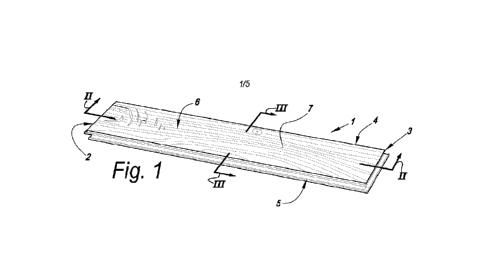
Figure 1 in perspective represents a floor panel with the characteristics
of the invention;
Figures 2 and 3, at a larger scale, represent a cross-section according
to the lines II-II and III-Ill, respectively, represented in Figure 1;
Figure 4, in a view similar to that of Figure 2, represents a variant;
Figure 5, at a larger scale, represents the floor panel of Figure 4 in
coupled condition;
Figure 6, at a larger scale, shows a view onto the region indicated by
F6 in Figure 2;
Figure 7, in a view similar to that of Figure 6, represents a variant;
23
CA 03195946 2023-4- 17
WO 2022/115462
PCT/US2021/060586
Figures 8 and 9 illustrate a step in a method with the characteristics of
the invention;
Figure 10 represents a variant in a view onto the region indicated by
F10 in Figure 8; and
Figure 11 on a larger scale represents another variant of a floor panel
in a view similar in accordance with the are indicated as Fl 1 on Figure 7.
DETAILED DESCRIPTION OF THE DRAWINGS
Figure 1 represents a decorative panel, more particularly a floor panel
1, in accordance with the invention. The panel 1 is rectangular and oblong and
comprises a pair of opposite short edges 2-3 and a pair of opposite long edges
4-5. The decorative top layer 6 is formed by a wood veneer 7 with a thickness
of 1 millimeter or less, in this case the veneer has a thickness Ti of
approximately 0.6 millimeters.
Figure 2 clearly shows that the decorative panel 1 comprises a
substrate material 8 on which the wood veneer 7 is provided by a layer on the
basis of thermosetting resin 9, situated between the substrate and the
decorative layer. In the example, the substrate 8 has an average density of
more than 750 kilograms per cubic meter. In this case, this relates to an HDF
board material with an average density of 900 kilograms per square meter and
a surface density of more than 1000 kilograms per square meter. At the edges
2-3 and 4-5, mechanical coupling structure(s) 10 are formed in the substrate
material by milling cutters. At the underside of the substrate material 8, a
backing layer 11 is provided, for example, glued or otherwise attached to the
substrate material 8. According to a preferred embodiment of the invention,
such backing layer 11 is also attached to the substrate material 8 by a layer
of thermosetting resin. Such backing layer 11 preferably is made of a wooden
veneer layer with a thickness T2 of at least 50 percent of the decorative top
layer. Still better, the decorative top layer of the wood veneer 7 and the
backing layer 11 differ from each other at least in that the wood veneer of
the
backing layer 11 is thicker than the wood veneer 7 of the top layer. The
24
CA 03195946 2023-4- 17
WO 2022/115462
PCT/US2021/060586
backing layer 11 may consist, for example, of a "rotary peeled veneer" with a
thickness T2 of 1.5 millimeters or thicker, whereas the wood veneer 7 of the
top layer is a veneer with a thickness Ti of less than 1 millimeter.
Figures 2 and 3 represent that both pairs of opposite edges 2-3-4-5 are
provided with mechanical coupling structure(s) 10 which substantially are
realized as a tongue 12 and a groove 13 bordered by an upper lip 14 and a
lower lip 15, wherein the tongue 12 and the groove 12 substantially are
responsible for the locking in a vertical direction V, and wherein the tongue
12
and the groove 13 are provided with additional locking parts 16-17, which
substantially are responsible for the locking in a horizontal direction H.
Preferably, the locking parts comprise a protrusion 16 at the underside of the
tongue 12 and a recess 17 in the lower groove lip 15. The coupling
structure(s)
10 represented in figures 2 and 3 allow at least a coupling by an angling or
rotational movement W around the respective edges 2-3-4-5 and/or a coupling
by a shifting movement S in a substantially horizontal manner of the edges 2-
3-4-5 to be coupled towards each other.
Figures 4 and 5 represent a variant with a pair of short edges 2-3, which
allow obtaining a coupling at least by a downward movement D. An edge 2 is
provided with a male coupling part 18, whereas the other edge 3 is provided
with a female coupling part 19. By the downward movement D the male
coupling part 18 is pressed into the female coupling part 19 in order to be
locked there in the vertical direction V, as a result of a pair of cooperating
protrusions 20 and recesses 21. In this case, the recess 21 is partially
formed
by a resilient element 22 present in the female coupling part 19.
Figure 6 represents a detail of the upper edge of the floor panel from
figure 2. It is shown clearly that the layer of thermosetting resin 9 can
penetrate
partially into the substrate material 8 and partially into the wood veneer 7
of
the top layer.
Figure 6 further clearly shows that the decorative layer 6 at the surface
comprises a lacquer layer 23 of a transparent or translucent surface material.
CA 03195946 2023-4- 17
WO 2022/115462
PCT/US2021/060586
In this case, this relates to a material with a matte structure, namely with a
gloss degree of 10 or less, as measured according to DIN 67530.
The floor panel from the Figures 1 to 6 is provided with lower edge
regions 24 on one or more edges 2-3-4-5, wherein the wood veneer 7 extends
in one piece from on the surface 25 of the substrate 8 over these lower edge
regions 24. In the example, the lower edge regions 24 are realized as bevel
or chamfer. The wood veneer 7 extends over the lower edge region 24 at least
up to a point 26, wherein the veneer surface is situated at a level L in a
horizontal plane which intersects the aforementioned substrate 8. At the
location of the lower edge regions 24, the wood veneer 7, seen on average,
has a thickness TB which is smaller than the global thickness Ti of the wood
veneer 7. At these edges, the wood veneer 7 is compressed or impressed. In
the present case, also the substrate material 8 is impressed at the location
of
these edges. This compression of the wood veneer 7 leads to an increased
resistance against moisture penetration. Preferably, the average thickness TB
of the wood veneer on the lower edge regions is less than 85% of the global
thickness Ti of the wood veneer. Instead of working with a compressed wood
veneer 7, in accordance with a not represented embodiment, a lower edge
region may be created by removing an amount of material from the veneer 7
at the respective edge. Such is preferably executed before application of the
lacquer 23.
Figure 7 represents a variant of the floor panel of the Figures 1 to 6,
where such lowered edge regions are absent, or where, in other words, the
wood veneer 7 extends to one or more or all of the edges 2-3-4-5 of the floor
panel 1 in a substantially horizontal manner.
In the examples, the thermosetting resin 9 extends uninterruptedly
underneath the entire wood veneer 7, inclusively the lower edge regions 24.
The surface material 23 follows the relief of the wood veneer 7 at least
over the lowered edges 24 or chamfers.
26
CA 03195946 2023-4- 17
WO 2022/115462
PCT/US2021/060586
Figure 6 schematically represents that the thermosetting resin 9 or the
glue layer comprises third hard particles 27. In this example, the third hard
particles 17 show an average particle size which is at least one third of the
thickness Ti of the wood veneer 7. These particles penetrate at the underside
into the wood veneer 7 and there provide for a barrier against the final
wearing
through of the veneer 7. Due to the choice of the average particle size, the
particles 27 penetrate from on the underside into the veneer 7 over a distance
which is larger than the distance D, wherein the distance D is 20% of the
thickness Ti of the wood veneer 7.
In accordance with the first aspect of the invention, also in the surface
material of the lacquer 23 there are wear-resistant particles, however, with a
smaller average particle size, for example, of 10 micrometers or smaller.
Figures 6 and 7 represent that, in accordance with the first aspect of
the invention, the lacquer 23 at least partially covers a side edge 28 of the
wood veneer 7. In this case it concerns the side edge 28 of the wood veneer
7 formed at a short edge 3 of the panel 1. The wood veneer 7, as illustrated
on Figure 1, has been cross cut, and may have open wood vessels, which are
sealed by the lacquer 23.
Figure 9 represents a pressing step in a method for manufacturing, e.g.
the panels of Figures 1 to 6. A stack 29, comprising the wood veneer 7 and a
basic board 8A, is pressed. For the press treatment in this case a structured
press element 30 is applied. The stack 29 comprises a basic board 8A with
an average density of more than 750 kilograms per cubic meter, a layer of
thermosetting resin 9 and a wood veneer 7 for forming the decorative top layer
6. Further, the stack 29 also comprises a wood veneer for forming the backing
layer 11 and a layer of thermosetting resin 9 for attaching this backing layer
11 to the underside of the basic board 8A. In the figure, the layers with
thermosetting resin 9 are shown in exploded view, but are in reality applied
to
the surface 25 of the basic board 8A, for example by a roller application. The
wood veneer 7 comprises a sewing connection 31, which is positioned above
a portion 32 of the basic board 8A, which has to be removed in subsequent
27
CA 03195946 2023-4- 17
WO 2022/115462
PCT/US2021/060586
treatments for subdividing and profiling or forming of coupling structure(s)
10,
which here already are represented in dashed line. In the example, the basic
board 8A comprises a flat upper surface 25. However, it is not excluded
that the upper surface may be pre-formed, entirely or partially, corresponding
to the applied press element 30.
Figure 10 represents the obtained pressed whole 33. Herein, the
decorative top layer 6 and the backing layer 11 is represented only
schematically each time as one layer, namely without representing the layers
with resin 9. From this, it is clear that the veneer 7 and the backing layer
11
are adhered to the basic board 8A by the hardened resin 9. Moreover, the
basic board 8A is deformed such that the upper surface 25 shows a structure.
The wood veneer 7 follows the contour of the structured upper surface 25.
Hereby, in this case, it is obtained that the wood veneer 7 comprises a relief
of scraped parquet with lowered edges 24.
Figure 10 represents that at least the third hard particles 27 can remain
absent at the location of the portion 32. In this manner it is achieved that
the
cutting tools, which have to remove the portion 32 in order to form the
coupling
structure(s), are less subjected to wear. In this case, an embodiment is
represented wherein the resin 9 and the hard particles 27 are areawise
applied to the stack 29, ie in areas with an intermediate space 34. Herein,
the
space 34 is situated above the portion 32 and in this case extends at least
over this entire portion. According to the variant represented in dashed line
35, it is also possible that the resin 9 extends continuously over the portion
32, however, that the third hard particles 27 remain absent there or anyhow at
least are present to a much more limited extent.
Figure 10 further represents that, whether or not in combination with
the above, a plurality of wood veneers 7 situated next to each other can be
applied instead of veneers which are composed, via a sewing connection, to
a continuous sheet. Preferably, between the wood veneers 7 a space is
maintained at the location of the portion 32. The dashed line 36 represents a
28
CA 03195946 2023-4- 17
WO 2022/115462
PCT/US2021/060586
continuous sheet which may or may not have a seam for example due to a
sewing connection 31.
Figure 10 further also represents that there are similar options for the
glue layer at the underside and for the backing layer 11.
Referring to Figures 9 to 10, it is clear that the press treatment
preferably is performed on a larger basic board 8A, which finally shall be
subdivided into a plurality of floor panels 1. In transverse direction as well
as
in longitudinal direction, a plurality of floor panels 1 lying next to each
other
can be formed from the larger basic board 8A. The portions 32 of the basic
board 8A can be present between adjacent long edges 4-5 as well as between
adjacent short edges 2-3 of the final floor panels 1.
Preferably subsequent to the dividing operation the lacquer layer 23 is
applied to the surface of the wood veneer 7 and to the side edge 28 of the
wood veneer 7.
Figure 11 shows an embodiment where the lacquer layer 23 comprises
at least two sublayers 23a-23b. In the example, only the uppermost sublayer
23a covers a part of the side edge 28 of the wood veneer 7. The other of the
two sublayers 23b extends up until the upper edge of the wood veneer 7.
Preferably, both the uppermost sublayer 23a and the other sublayer 23b
comprise hard particles, not shown here. Preferably the hard particles of the
uppermost sublayer 23a are of a smaller average particle size than the hard
particles of the other sublayer 23b. Preferably the uppermost sublayer 23a
has a thickness Ta which is smaller, preferably at least 30% smaller, than the
thickness Tb of the other sublayer 23b.
Figure 11 further illustrates by the dashed lines 37 that a lowered edge
24 can be realized by removing an amount of material from the wood veneer
7 at the respective edge 3. Preferably the lacquer layer 23 is available on
the
surface of the lowered edge 24, and preferably at least the uppermost layer
23a ¨ in this case only the uppermost layer 23a - extends over the upper edge
to cover at least a part of the side edge 28 of the wood veneer 7.
29
CA 03195946 2023-4- 17
WO 2022/115462
PCT/US2021/060586
The present invention is in no way limited to the herein above-described
embodiments, on the contrary can such methods and decorative panels be
realized according to various variants, without leaving the scope of the
present
invention. Amongst others, it is clear that the characteristics of the
invention
of any aspect also are interesting with other decorative panels, such as
furniture panels, wall panels or ceiling panels. So, for example, does the
invention offer the possibility for more wear-resistant counter tops for
kitchens,
office furniture, tables and the like, which comprise only a thin veneer layer
as
a decorative layer.
Although in the above practically exclusively wood veneer is
mentioned, it is evident that the above independent aspects and preferred
embodiments thereof also are applied in decorative panels with a thin top
layer
of another material. So, for example, it can be applied in decorative top
layers
of leather, bamboo, textile, aluminum, metal, stone veneer, plastic foils or
the
like.
CA 03195946 2023-4- 17