Note: Descriptions are shown in the official language in which they were submitted.
ROTARY OPEN-CLOSE TYPE SUN UMBRELLA
TECHNICAL FIELD
This invention generally relates to the technical field of sun umbrellas, and
more
particularly, to a rotary open-close type sun umbrella.
BACKGROUND
Sun umbrellas are necessities of people's daily lives that function as a
protection
against the sun. They are often used in rest areas such as courtyards for
providing a
comfortable shade. With the improvement of people's living standards, sun
umbrellas have
become popular and widespread.
Presently, there are various sun umbrellas sold on the market. Conventional
sun
umbrellas may be divided into middle-post umbrellas, hanging umbrellas and
bent-arm
umbrellas, wherein middle-post umbrellas are merely suitable for being
inserted in the
middle of a table. When users rest around a table, the umbrella post blocks
their sight lines,
resulting in poor use experience and narrowed application range. Hanging
umbrellas and
bent-arm umbrellas are suitable for courtyards and public places with
suspended ceilings.
However, their shortcomings such as large space occupation, complex structure,
high
material cost and high manufacturing cost are unavoidable. Therefore, it is
urgent for those
skilled to develop a novel sun umbrella.
SUMMARY
The purpose of the present invention is to provide a rotary open-close type
sun
umbrella having a reasonable structure, capable of providing a one-sided
shade, and capable
of being flexibly unfolded, folded and conveniently stored.
To achieve the above purpose, the present invention adopts the following
technical
solution: a rotary open-close type sun umbrella comprises a standing post,
umbrella ribs and
umbrella cloths; an unfolding device is arranged at the upper end of the
standing post, and
the unfolding device is rotatably connected with the standing post; a
plurality of umbrella
- 1 -
CA 3197189 2023-04-14
ribs are arranged on the unfolding device, and the plurality of umbrella ribs
are connected to
a plurality of umbrella cloths; each umbrella cloth is connected with two
adjacent umbrella
ribs, thereby enabling the plurality of umbrella ribs and the plurality of
umbrella cloths to be
sequentially connected to form an umbrella surface; the standing post is
provided with a
driving device, and the driving device is in transmission connection with the
unfolding
device, which allow the umbrella surface to be unfolded or folded.
In another embodiment of the present invention, the upper end of the standing
post is
provided with a steering mechanism, and the lower end of the unfolding device
is connected
to the steering mechanism in an interacting mode, thus forming an included
angle C between
the unfolding dpvice and the standing post. The driving device is connected to
the unfolding
device through the steering mechanism.
In another embodiment of the present invention, the unfolding device comprises
a
plurality of rotating aims, the plurality of rotating arms is sequentially
arranged on a same
center shaft, and an included angle C is formed between the center shaft and
the standing
=
post. One end of each umbrella rib is fixedly connected to a corresponding
rotating arm. The
rotating arm at the lowermost end in the unfolding device is rotatably
connected to the
steering mechanism, and a limiting structure is arranged between the rotating
arm and the
steering mechanism. The rotating arm at the uppermost end in the unfolding
device is in
transmission connection with the steering mechanism, so that the driving
device can drive
the umbrella surface to unfold or fold through the plurality of rotating arms.
In another embodiment of the present invention, the steering mechanism is
provided
with a mandrel, and the lower end of the mandrel is rotatably connected to the
steering
mechanism through a bearing. The mandrel is arranged within the plurality of
rotating arms
along a central axis in a penetrating manner, and the mandrel is provided with
a plurality of
shaft sleeves that correspond to the rotating arms in a one-to-one manner. The
rotating arm
at the uppermost end in the unfolding device is fixedly connected to the
mandrel through a
shaft sleeve. The shaft sleeves corresponding to the rest of rotating arms are
respectively
- 2 -
CA 3197189 2023-04-14
provided with a bearing, and the rest of rotating arms are rotatably connected
to the mandrel
through shaft sleeves.
In another embodiment of the present invention, the steering mechanism
comprises a
first bent pipe and .a second bent pipe. The lower end of the first bent pipe
is fixed to the
upper end of the second bent pipe, and an included angle C is formed between
the first bent
pipe and the second bent pipe. The first bent pipe is provided with a mandrel,
the lower end
of the mandrel is rotatably arranged in the first bent pipe in a penetrating
mode through a
=
bearing, and the upper end of the mandrel is connected to the unfolding device
in an
interacting mode. A transmission rod is arranged in the standing post, and the
lower end of
the second bent pipe is fixedly connected with the upper end of the standing
post. The upper
end of the transmission rod is arranged in the second bent pipe in a
penetrating mode, and
the transmission rod is respectively connected to the second bent pipe and the
standing post
through bearings. The upper end of the transmission rod is in transmission
connection with
the lower end of the mandrel, and the driving device is in transmission
connection with the
.. lower end of the transmission rod.
In another embodiment of the present invention, the lower end of the mandrel
and the
upper end of the transmission rod are engaged by two bevel gears to form a
transmission
connection.
In another embodiment of the present invention, the lower end of the mandrel
and the
upper end of the transmission rod form a transmission connection by means of a
universal
joint.
In another embodiment of the present invention, a limiting device is arranged
between
the first bent pipe and the rotating arm at the lowermost end in the unfolding
device. The
limiting structure comprises an extension plate and a stop block. The inner
wall of the upper
opening of the first bent pipe is provided with a stop block, and the lower
opening of the
shaft sleeve close to the first bent pipe is provided with an extension plate.
The extension
plate is arranged in the upper opening of the first bent pipe in a penetrating
manner. When
- 3 -
CA 3197189 2023-04-14
the rotating arm on the shaft sleeve rotates around the mandrel, the extension
plate and the
stop block interact with each other in the circumferential direction of the
center shaft.
In another embodiment of the present invention, the driving device comprises a
hand
rocker and a speed variator. The speed variator is fixedly arranged in the
middle of the
standing post and is in transmission connection with the lower end of the
transmission rod.
The hand rocker is arranged on the speed variator.
Compared with the prior art, the present invention has the following
advantages: the
present invention has a reasonable structure; the unfolding device is
propelled by a hand
rocker; the rotating arms are rotatably arranged on a mandrel; the mandrel
propels one of the
rotating arms and the corresponding umbrella rib to rotate; the plurality of
umbrella ribs are
connected through umbrella cloths such that an umbrella surface is formed
after the
umbrella cloths are unfolded sequentially; an included angle C is formed
between the
unfolding device and the standing post; when folded, the rotating arms are
attached to the
standing post, thereby reducing the space occupation while achieving a
flexible use.
BRIEF DESCRIPTION OF THE DRAWINGS
Figure 1 is a conceptual diagram illustrating an explosive view of the main
body without
umbrella cloths of the present invention.
Figure 2 is conceptual diagram illustrating an explosive view of the steering
mechanism in
embodiment 1 of the present invention.
Figure 3 is a conceptual diagram illustrating a sectional view of the present
invention.
Figure 4 is a conceptual diagram illustrating an enlarged structure of portion
A in Figure 3.
Figure 5 is a conceptual diagram illustrating an overall structure of the
present invention in a
folded state.
Figure 6 is a conceptual diagram illustrating an overall structure of the
present invention in
an unfolded state.
Figure 7 is conceptual diagram illustrating an explosive view of the steering
mechanism in
embodiment 2 of the present invention.
- 4 -
CA 3197189 2023-04-14
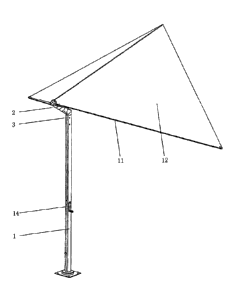
In Figures: 1-Standing Post, 2-Unfolding Device, 3-Steering Mechanism, 11-
Umbrella Rib,
12-Umbrella Cloth, 13-Transmission Rod, 14-Hand Rocker, 15-Speed Variator, 21-
Rotating
Arm, 22-Extension Plate, 31-Mandrel, 32-Shaft Sleeve, 33-The First Bent Pipe,
34-The
Second Bent Pipe, 35-Stop Block, 36-Bevel Gear, 37-Universal Joint.
DETAILED DESCRIPTION
Drawings and detailed embodiments are combined hereinafter to elaborate the
technical
solution of the present invention.
Embodiment 1
As shown in Figures 1-6, the rotary open-close type sun umbrella of the
present
invention comprises a standing post 1, umbrella ribs 11 and umbrella cloths
12. An
unfolding device 2 is arranged at the upper end of the standing post 1, and
the unfolding
device 2 is rotatably connected with the standing post 1. A plurality of
umbrella ribs 11 are
arranged on the unfolding device 2, and the plurality of umbrella ribs 11 are
connected to a
plurality of umbrella cloths 12. Each umbrella cl6th 12 is connected with two
adjacent
umbrella ribs 11. Thus, the plurality of umbrella ribs 11 and the plurality of
umbrella cloths
12 are sequentially connected to form an umbrella surface. The standing post 1
is provided
with a driving device, and the driving device is ,in transmission connection
with the
unfolding device 2, thereby allowing the umbrella surface to be unfolded or
folded. The
umbrella cloths 12 are connected with the umbrella ribs 11 to form an umbrella
surface, and
one end of each umbrella rib 11 is connected with the unfolding device 2. In
this way, when
the umbrella surface is unfolded by using the unfolding device 2, and when the
unfolding
angle or rotating angle of the unfolding device 2 is less than 360 degrees,
the umbrella
surface forms a non-full-circle structure. Alternatively, when the unfolding
angle or rotating
angle of the unfolding device 2 is 360 degrees, the umbrella surface form a
full-circle
structure around the standing post 1. Preferably, in this embodiment, the
unfolding angle of
the unfolding device 2 is near 180 degrees. The umbrella ribs 11 and umbrella
cloths 12
form a semi-circular umbrella surface when being driven by the unfolding
device 2.
- 5 -
CA 3197189 2023-04-14
Through adopting the present invention, the technical problem that the
standing post needs
to be arranged at the center of the table top is solved. The lower end of the
standing post 1 is
provided with a fixing structure, such as a bottom foot or a bottom plate,
which enables the
standing post 1, the unfolding device 2, the umbrella ribs 11 and the umbrella
surface to be
stably arranged on the ground, thereby stably providing a shade for the user.
The upper end of the standing post 1 is provided with a steering mechanism 3,
and the
lower end of the unfolding device 2 is connected to the steering mechanism 3
in an
interacting mode, thereby forming an included angle C between the unfolding
device 2 and
the standing post 1. The driving device is connected to the unfolding device 2
through the
steering mechanism 3. The steering mechanism 3 allows the unfolding device 2
to be
obliquely arranged at the upper end of the standing post 1. The included angle
C formed
between the unfolding device 2 and the standing post 1 enables the plurality
of umbrella ribs
11 arranged around the unfolding device 2 to droop in a folded state.
Moreover, the umbrella
ribs 11 may be approximately parallel to the standing post 1, so that the
space occupation of
the sun umbrella is significantly reduced during storage and transportation.
Definitely, the
included angle C ranges from 45 to 75 degrees, and an included angle is formed
between
each umbrella rib 11 and the rotating shaft of the unfolding device 2. Thus,
when being
folded, the umbrella ribs 11 are in a drooping state.
The unfolding device 2 comprises a plurality of rotating arms 21, the
plurality of
rotating arms 21 are sequentially arranged on a same center shaft, and an
included angle C is
formed between the center shaft and the standing post 1. One end of each
umbrella rib 11 is
fixedly connected to a corresponding rotating arm 21. The rotating arm 21 at
the lowermost
end in the unfolding device 2 is rotatably connected to the steering mechanism
3, and a
limiting structure is arranged between the rotating arm 21 and the steering
mechanism 3.
The rotating arm 21 at the uppermost end in the unfolding device 2 is in
transmission
connection with the steering mechanism 3, so that the driving device can drive
the umbrella
surface to unfold or fold through the plurality of rotating arms 21. The
rotating arm 21 may
- 6 -
CA 3197189 2023-04-14
rotate around the central axis of the unfolding device 2, and the rotating arm
21 at the
uppermost end in the unfolding device 2 is driven by the steering mechanism 3.
The
umbrella rib 11 connected to the rotating arm 21 at the uppermost end in the
unfolding
device 2 rotates around the center shaft and sequentially, drives other
umbrella ribs 11 and
rotating arms 21 through the umbrella cloth 12. Thus, the plurality of
umbrella ribs 11 and
the umbrella cloths 12 are sequentially unfolded to form an umbrella surface.
After the
umbrella surface is formed, the rotating arm 21 at the lowermost end in the
unfolding device
2 and the steering mechanism 3 are connected through a limiting structure,
thereby
preventing the rotating arm 21 from rotating. Preferably, the plurality of
rotating arms 21 of
the unfolding device 2 are sequentially linked through the umbrella cloths 12.
Contrarily,
when the rotating arm 21 at the uppermost end rotates reversely, other
rotating arms 21 may
also be driven such that the plurality of umbrella ribs 11 render a drooping
state.
The steering mechanism 3 is provided with a mandrel 31, and the lower end of
the
mandrel 31 is rotatably connected to the steering mechanism 3 through a
bearing. The
mandrel 31 is arranged within the plurality of rotating arms 21 along a
central axis in a
penetrating manner, and the mandrel 31 is provided with a plurality of shaft
sleeves 32 that
correspond to the rotating arms 21 in a one-to-one manner. The rotating arm 21
at the
uppermost end in the unfolding device 2 is fixedly connected to the mandrel 31
through a
shaft sleeve 32. The shaft sleeves 32 corresponding to the rest of rotating
arms 21 are
respectively provided with a bearing, and the rest of rotating arms 21 are
rotatably connected
to the mandrel 31 through shaft sleeves 32. The shaft sleeves 32 are arranged
on the mandrel
31 through bearings, and the shaft sleeves 32 are connected to the rotating
arms 21 in an
interacting mode. Thus, the shaft sleeves are axially limited, and the
plurality of rotating
arms 21 are enabled to rotate relatively around the center shaft. Further, the
rotating arm 21
at the uppermost end in the unfolding device 2 is fixedly connected to the
mandrel 31
through a shaft sleeve 32. When the driving device propels the mandrel 31 to
rotate through
the steering mechanism 3, the mandrel 31 propels the rotating arm 21 at the
uppermost end
- 7 -
CA 3197189 2023-04-14
to rotate. In this way, the plurality of rotating arms 21, umbrella ribs 11
and umbrella cloths
12 are sequentially unfolded to form an umbrella surface.
The steering mechanism 3 comprises a first bent pipe 33 and a second bent pipe
34.
The lower end of the first bent pipe 33 is fixed to the upper, end of the
second bent pipe 34,
and an included angle C is formed between the first bent pipe 33 and the
second bent pipe
34. The first bent pipe 33 is provided with a mandrel 31, the lower end of the
mandrel 31 is
rotatably arranged in the first bent pipe 33 in a penetrating mode through a
bearing, and the
upper end of the mandrel 31 is connected to the unfolding device 2 in an
interacting mode.
A transmission rod 13 is arranged in the standing post 1, and the lower end of
the second
bent pipe 34 is fixedly connected with the upper end of the standing post 1.
The upper end of
the transmission rod 13 is arranged in the second bent pipe 34 in a
penetrating mode, and the
transmission rod 13 is respectively connected to the second bent pipe 34 and
the standing
post 1 through bearings. The upper end of the transmission rod 13 is in
transmission
connection with the lower end of the mandrel 31, and the driving device is in
transmission
connection with the lower end of the transmission rod 13. Because an included
angle C is
formed between the unfolding device 2 and the standing post 1, the driving
device needs the
steering mechanism to realize a transmission connection. The first bent pipe
33 and the
second bent pipe 34 are respectively connected to the unfolding device 2 and
the standing
post 1. The first bent pipe 33 is rotatably connected to the unfolding device
2 through the
mandrel 31, and the mandrel 31 is fixedly connected to the uppermost end of
the rotating
arm 21 to achieve a rigid transmission. To prevent the plurality of rotating
arms 21 from
being separated from the upper end of the mandrel 31, the upper end of the
mandrel 31 is
provided with a cover plate for fixing the unfolding device 2.
The lower end of the mandrel 31 and the upper end of the transmission rod 13
are
engaged by two bevel gears 36 to form a transmission connection. The steering
mechanism
3 is used for forming an included angle C between the unfolding device 2 and
the standing
post 1. An included angle C is also formed between the mandrel 31 and the
transmission rod
- 8 -
CA 3197189 2023-04-14
13, and the mandrel 31 is rotatably arranged in the first bent pipe 33 through
a bearing. The
transmission rod 13 is rotatably arranged in the standing post 1 through a
bearing. The
transmission rod 13 and the mandrel 31 are engaged by means of the two bevel
gears 36,
thereby achieving the power transmission between the transmission rod 13 and
the mandrel
31. In this way, the driving device propels the unfolding device 2 to unfold
or fold the
umbrella surface.
A limiting device is arranged between the first bent pipe 33 and the rotating
arm 21 at
the lowermost end in the unfolding device 2. The limiting structure comprises
an extension
plate 22 and a stop block 35. The inner wall of the upper opening of the first
bent pipe 33 is
provided with a stop block 35, and the lower opening of the shaft sleeve 32
close to the first
bent pipe 33 is provided with an extension plate 22. The extension plate 22 is
arranged in the
upper opening of the first bent pipe 33 in a penetrating manner. When the
rotating arm 21 on-
the shaft sleeve 32 rotates around the mandrel 31, the extension plate 22 and
the stop block
35 interact with each other in the circumferential direction of the center
shaft. The limiting
device is used for limiting the moving angle of the rotating arm 21 at the
lowermost end on
the mandrel 31. When the rotating angle of the rotating arm 21 at the
uppermost end exceeds
180 degrees, the umbrella cloth 12 on this rotating arm 21 is completely
unfolded, and other
umbrella ribs 11 and umbrella cloths 12 are also propelled to be unfolded to
form an
umbrella surface. At this point, the extension plate 22 abuts against the stop
block 35 to
prevent the rotating arm 21 at the lowermost end from rotating continuously,
thereby
enabling the unfolding device 2 to respectively unfold the plurality of
umbrella ribs 11 and
umbrella cloths. Thus, a stable sun umbrella surface is formed on the standing
post 1.
The driving device comprises a hand rocker 14 and a speed variator 15. The
speed
variator 15 is fixedly arranged in the middle of the standing post 1 and is in
transmission
connection with the lower end of the transmission rod 13. The hand rocker 14
is arranged on
the speed variator 15. Preferably, in the present invention, a hand rocker 14
and a speed
variator 15 are adopted to propel the transmission rod 13 and the unfolding
device 2.
- 9 -
CA 3197189 2023-04-14
Definitely, the driving device may also adopt an electric mode, namely, a
motor being
arranged on the transmission device 15 for serving as a power source.
Correspondingly, the
limiting device is provided with a movement control sensor, and the motor is
turned off
when the umbrella surface is fully unfolded.
Embodiment 2
As shown in Figure 7, the difference between embodiment 7 and embodiment 1 is
that
a transmission connection is formed between the lower end of the mandrel 31
and the upper
end of the transmission rod 13 by means of a universal joint 37. The steering
mechanism 3 is
used for forming an included angle C between the unfolding device 2 and the
standing post
1. Similarly, an included angle C is also formed between the mandrel 31 and
the
transmission rod 13. The mandrel 31 is rotatably arranged in the first bent
pipe 33 through a
bearing, and the transmission rod 13 is rotatably arranged in the standing
post 1 through a
bearing. The mandrel 31 and the transmission rod 13 are connected through the
universal
joint 37 such that power transmission is realized between the transmission rod
13 and the
mandrel 31. In this way, the driving device is capable of propelling the
unfolding device 2 to
unfold or fold the umbrella surface.
The above are merely preferred embodiments of the present invention.
Therefore,
equivalent changes or modifications made according to the structures, features
and
principles described in the specification of the present invention shall fall
into the scope
defined by the claims of the present invention.
- 10 -
CA 3197189 2023-04-14