Note: Descriptions are shown in the official language in which they were submitted.
WO 2022/098802
PCT/US2021/057963
ELECTRONIC DEVICES FOR AEROSOLIZING AND INHALING LIQUID
COPYRIGHT STATEMENT
[001] All of the material in this patent document is subject to copyright
protection under the
copyright laws of the United States and other countries. The copyright owner
has no objection to the
facsimile reproduction by anyone of the patent document or the patent
disclosure, as it appears in official
governmental records but, otherwise, all other copyright rights whatsoever are
reserved.
BACKGROUND OF THE INVENTION
[002] The invention generally relates to apparatus, systems, and methods
for producing an aerosol
for inhalation by a person, whether intended for personal or recreational use,
or for the administration of
medicines.
[003] Vaping has been rapidly increasing in popularity, primarily because
vaping provides a
convenient, discreet, and presumably benign way to self-administer nicotine,
cannabis, drugs, or other
micronutrients. Indeed, there is a common belief that vaping is healthier than
smoking cigarettes; vaping
purportedly lets smokers avoid dangerous chemicals inhaled from regular
cigarettes while still getting
nicotine. Vaping also can be used for cannabis.
[004] Vaping is performed using a vaporizer. A vaporizer includes a vape
pen or a cigarette style
vape, referred to by many as an e-cigarette or "eCig-. A vape pen generally is
an elongate, thin, and
stylized tube that resembles a fancy pen. In contrast, an e-cigarette
resembles an actual cigarette. The e-
cigarette is usually small in size (usually smaller and more discreet than
vape pens), easily portable, and
easy to use.
[005] A common vaporizer comprises a container, which may be a tank¨which
is typically
refillable, or a cartridge¨which is typically single-use and not refillable.
The tank or cartridge holds a
liquid often referred to as an e-liquid or e-juice. Tanks typically are made
out of polycarbonate plastic,
glass, or stainless steel. The vaporizer also includes a mouthpiece for
inhaling by a person through the
mouth; an atomizer comprising a tiny heating element that converts the liquid
into tiny, airborne droplets
that are inhaled; and a controller for turning on the atomizer. Many vape pens
are mouth-activated and
turn on automatically when a person inhales. Others vape pins are button
activated and require the person
to push a button to activate the atomizer. Vaporizers are electrically powered
using one or more batteries.
The batteries typically are lithium ion batteries that are rechargeable and
primarily are used to heat the
heating element of the atomizer. A charger usually accompanies a vaporizer
when purchased for
charging the batteries. The charger may be a USB charger; car charger, or wall
charger, and such
chargers are generally similar to phone chargers.
[006] The battery-powered vaporizer produces vapor from any of a variety of
liquids and liquid
mixtures, especially those containing nicotine or cannabinoids. Many diverse
types and flavors are
available. Moreover, the liquids can be non-medicated (i.e., containing no
nicotine or other substances
just pure vegetable glycerin and flavoring), or the liquids can contain
nicotine or even in some instances if
1
CA 03197266 2023- 5-2
WO 2022/098802
PCT/US2021/057963
and where legal, the liquids can contain THC/CBD. The liquids also may contain
one or more of a
variety of flavors as well as micronutrients such as, for example, vitamin
B12. A person can mix the
liquids for usc with a vapc pen. Vaporizers typically arc purchased with
prefilled cartridges. The heating
element turns the contents of the liquids into an aerosol¨the vapor¨that is
inhaled into the lungs and
then exhaled by the person. Perhaps one of the most popular vaporizers today
is known as the "JUUL",
which is a small, sleek device that resembles a computer USB flash drive.
[007] It is believed that, while promoted as healthier than traditional
cigarette use, vaping actually
may be more dangerous. Propylene glycol, vegetable glycerin and combinations
or methylations thereof,
are chemicals that are often mixed with nicotine, cannabis, or hemp oil for
use in vaporizers. Propylene
glycol is the primary ingredient in a majority of nicotine-infused e-cigarette
liquids. Unfortunately, at
high temperatures propylene glycol converts into tiny polymers that can wreak
havoc on lung tissue. In
particular, scientists know a great deal about propylene glycol. It is found
in a plethora of common
household items¨cosmetics, baby wipes, pharmaceuticals, pet food, antifreeze,
etc. The U.S. Food and
Drug Administration and Health Canada have deemed propylene glycol safe for
human ingestion and
topical application. But exposure by inhalation is another matter. Many things
are safe to eat but
dangerous to breathe. Because of low oral toxicity, propylene glycol is
classified by the FDA as
-generally recognized as safe" (GRAS) for use as a food additive, but this
assessment was based on
toxicity studies that did not involve heating and breathing propylene glycol.
Indeed, a 2010 study
published in the International Journal of Environmental Research and Public
Health concluded that
airborne propylene glycol circulating indoors can induce or exacerbate asthma,
eczema, and many allergic
symptoms. Children were said to be particularly sensitive to these airborne
toxins. An earlier toxicology
review warned that propylene glycol, ubiquitous in hairsprays, could be
harmful because aerosol particles
lodge deep in the lungs and are not respirable.
[008] Moreover, when propylene glycol is heated, whether by a red-hot metal
coil of a heating
element of a vaporizer or otherwise, the potential harm from inhalation
exposure increases_ It is believed
that high voltage heat transforms the propylene glycol and other vaping
additives into carbonyls.
Carbonyls are a group of cancer-causing chemicals that includes formaldehyde,
which has been linked to
spontaneous abortions and low birth weight. A known thermal breakdown product
of propylene glycol,
formaldehyde is an International Agency for Research on Cancer group 1
carcinogen!
[009] Prevalent in nicotine e-cigarette products and present in some vape
oil cartridges, FDA-
approved flavoring agents pose additional risks when inhaled rather than
eaten. The flavoring compounds
smooth and creamy (diacetyl and acetyl propionyl) are associated with
respiratory illness when inhaled in
tobacco e-cigarette devices. Another hazardous-when-inhaled-but-safe-to-eat
flavoring compound is
Ceylon cinnamon, which becomes cytotoxic when aerosolized.
[010] When a heating element gets red hot in a vaporizer, the liquid
undergoes a process called
µ`smoldering", which is a technical term for what is tantamount to "burning";
while much of thc liquid is
2
CA 03197266 2023- 5-2
WO 2022/098802
PCT/US2021/057963
vaporized and atomized, a portion of the liquid undergoes pyrolysis or
combustion. In that sense, most of
the vaporizers that have flooded the commercial market may not be true
vaporizers.
[011] It thus will be appreciated that as inhalation delivery systems using
heating have increased in
prominence, concerns about their short and long term safety have come into
focus. This is particularly
true for vaping where there exist ongoing concerns about the possible presence
of harmful and potentially
harmful constituents (HPHCs) in the inhaled vapor.
[012] Additionally, clearance mechanisms of the lung, like all major points
of contact with the
external environment, have evolved to prevent the invasion of unwanted
airborne particles from entering
the body. Airway geometry, humidity and clearance mechanisms contribute to
this filtration process.
Inhalation delivery systems are often unable to provide the desired effect to
a user because the pre-
vaporized liquid becomes unstable over time or the active ingredient itself is
not properly sized or
dispersed for deposition in the alveolar lung. This is a problem not only for
vaping, but for other
inhalation delivery systems that play an increasing role in the targeted
delivery of active ingredients to the
human pulmonary system. This is true both for medical purposes, such as the
targeted delivery of anti-
cancer medications to the lungs, as well as for recreational/personal
purposes, such as vaping.
[013] In view of the foregoing, it is believed that a need exists for a
vaporizer that provides an
aerosol of the desired chemicals without the harmful byproducts that arise
from smoldering. It is also
believed that a need exists for a vaporizer that effectively and efficiently
produces a vapor cloud that is
not inhibited by the body's natural filtration process. It further is believed
that a need exists for an active
ingredient delivery system that enhances the shelf-life of the pre-vaporized
liquid component and
enhances the efficacy of the desired treatment/effect, while avoiding the
presence of undesired HPHCs in
the inhaled vapor. One or more of these needs, and still other needs, are
believed to be met by one or
more respective embodiments in accordance with one or more aspects and
features of the invention.
SUMMARY OF THE INVENTION
[014] The invention includes many aspects and features, and generally
relates to apparatus,
systems, formulations, and methods pertaining to liquids that are aerosolized
and inhaled by persons
using electronic devices, whether intended for personal or recreational use,
or for the administration of
medicines. Moreover, while many aspects and features relate to, and are
described in, the context of
vaping, the invention is not limited to use only in such context. Indeed,
depending on the context of use,
the electronic device of the invention may be considered a vaporizer and may
be in the form of a vape pen
or c-cigarette. Indeed, those who vapc may come to refer to embodiments of the
invention as a vapc pen
even though heat is not utilized to create the aerosol that is inhaled. In the
delivery of pharmaceuticals,
patients may come to refer to embodiments of the invention as a nebulizer even
though a gas transport
(e.g., compressed gas) is not utilized and even though the aerosol that is
produced in accordance with the
invention may have a smaller particle size than the mist produced by common
nebulizers. Other separate
and distinct contexts of use of embodiments of -the invention may similarly
result in different
3
CA 03197266 2023- 5-2
WO 2022/098802
PCT/US2021/057963
nomenclature of the embodiments of the invention. Nonetheless, while the
appearance and form factor of
embodiments of the invention may vary depending on such contexts of use, the
basic components and
operation remain the same, except where otherwise described below.
[015] In an aspect of the invention, a cartridge assembly is configured to
couple with a handheld
base assembly and, preferably, are configured to magnetically couple. The
handheld base assembly
comprises electronics in the form of a printed circuit board and a power
source in the form of a battery,
which preferably is rechargeable. An electrical connection is made when the
cartridge assembly is
coupled with the handheld base assembly by which the cartridge assembly is
powered. The base also
preferably includes magnets that magnetically attract a metal plate of the
cartridge assembly to secure the
cartridge assembly within an opening in an end of the base. The cartridge
assembly preferably is a
disposable cartridge assembly.
[016] In accordance with this aspect, the cartridge assembly comprises a
cartridge and a bladder
assembly contained within the cartridge. In turn, the bladder assembly
comprises a bladder containing a
wick and a mesh assembly that sits on top of and covers a mouth of the
bladder. The wick acts to draw
liquid to the mesh assembly. The wick is retained in physical engagement with
the bladder proximate its
bottom by protuberances that extend from the walls of the bladder. There are
preferably four
protuberances that surround the end of the wick in a discontinuous circular
pattern and receive the end of
the wick in frictional fit with each of four sides. The wick extends therefrom
to and is retained in
physical engagement with the mesh assembly and, in particular, a piezoelectric
disk having a mesh
material which, when powered by the power source, vibrates so as to aerosolize
a liquid contained within
the bladder and wick. The mesh assembly is held in tension on top of a lip of
the mouth of the bladder by
a sealing 0-ring that is forced into engagement with the mesh assembly by the
attachment of a
mouthpiece of the cartridge assembly to the cartridge. Screws are preferably
utilized in effecting the
attachment whereby the force by which the 0-ring is held in contact with the
mesh assembly may be
adjusted. A spacer on a printed circuit board of the cartridge assembly may
additionally engage the
bottom of the silicone bladder and hold the wick in tension therethrough. Due
to these features, it is
believed that the bladder and wick ensure that the mesh remains in constant
contact with the liquid for
consistent aerosolization each time the electronic device is triggered. The
liquid preferably is supplied
to the vibrating mesh at a generally constant pressure whereby a generally
uniform aerosol is
produced, and this is accomplished regardless of the orientation of the
electronic device.
[017] In a feature, the cartridge assembly comprises a printed circuit
board or other electronics, and
the cartridge assembly communicates with the handheld base assembly when
coupled. Preferably, the
printed circuit board includes memory that includes information regarding the
liquid contained in the
bladder and dosing information related thereto, e.g., the number of doses
dispensed so far from the
cartridge assembly. The cartridge assembly further can be programmed to only
work with one or more
specified handheld base assemblies to the exclusion of other handheld base
assemblies. For example, a
4
CA 03197266 2023- 5-2
WO 2022/098802
PCT/US2021/057963
cartridge assembly could be configured to work only with a handheld base
assembly of a particular
person, e.g., a certain patient for whom a prescription is provided via the
cartridge assembly.
[018] In a feature, the wick has a lengthwise channel that extends between
its opposite ends. The
channel assists in delivery liquid to the mesh assembly for aerosolizing.
[019] In a feature, the wick is rigid.
[020] In a feature, opening cross sections of the mesh that is in contact
with the liquid is smaller
than the opening cross section that faces the mouthpiece and exit of the
aerosolized liquid. The taper
angle and size of the perforated mesh preferably is adjusted via electro-
forming methods to achieve a
laminar and non-turbulent aerosol that is best suited for deep lung
penetration and will, therefore, not
yield large amounts of buccal deposition.
[021] In a feature, an airflow channel is defined between the port of the
mouthpiece and a pressure
sensor located within the handheld base assembly. A D-ring is provided to seal
the interface between the
cartridge and the mouthpiece to prevent loss of suction along the airflow
channel. The airflow channel is
defined by openings in the mouthpiece, the cartridge, the printed circuit
board, the metal plate, and the
chassis. Furthermore, while one opening is shown in connection with the
mouthpiece in the drawings,
three openings preferable are provided that are equally spaced around the 0-
ring.
[022] In an aspect, the bladder may be filled with the liquid by injection
after assembly of the
cartridge assembly. Since the bladder preferably is a self-sealing silicone
bladder, when the injector
needle is removed, the bladder re-seals and no liquid drains or leaks out. In
this aspect, the liquid may be
injected as a last stop via an access port/injector port that is located on
the bottom of the cartridge.
Alternatively, the bladder is inserted into the cartridge and then is filled
with liquid first (top-down pour)
without utilizing a needle or puncturing the bladder with an injector needle.
In this manner, the bladder is
filled by pouring liquid into the bladder and, once the desired volume has
been dispensed, the wick is
inserted inside the bladder and then the bladder is capped off by the mesh
assembly and the rest of the
cartridge assembly is then assembled. The cartridge assembly preferably is a
disposable cartridge
assembly.
[023] Additional aspects and features of a preferred commercial system and
apparatus for dosing by
patients are disclosed in the drawings.
[024] In addition to the aforementioned aspects and features of the
invention, it should be noted that
the invention further encompasses the various logical combinations and
subcombinations of such aspects
and features. Thus, for example, claims in this or a divisional or continuing
patent application or
applications may be separately directed to any aspect, feature, or embodiment
disclosed herein, or
combination thereof, without requiring any other aspect, feature, or
embodiment.
CA 03197266 2023- 5-2
WO 2022/098802
PCT/US2021/057963
BRIEF DESCRIPTION OF THE DRAWINGS
[025] One or more preferred embodiments of the invention now will be
described in detail with
reference to the accompanying drawings, wherein the same elements arc referred
to with the same
reference numerals.
[026] FIG. lA illustrates an electronic device having a handheld base
assembly and a cartridge
assembly, in accordance with one or more preferred implementations of the
invention.
[027] FIG. 1B illustrates the act of separating the handheld base assembly
from the cartridge
assembly in the electronic device of FIG. 1A.
[023] FIG. 1C illustrates a close-up view of the cartridge
assembly after being separated from the
handheld base assembly as illustrated in FIG. 1B.
[029] FIG. 2A illustrates a front elevational view of the cartridge
assembly of FIG. 1C.
[030] FIG. 2B illustrates a rear elevational view of the cartridge assembly
of FIG. 1C.
[031] FIG. 2C illustrates a perspective view of the rear and a bottom of
the cartridge assembly
of FIG. 1C.
[032] FIG. 2D illustrates a perspective view of the bottom of the cartridge
assembly of FIG.
1C.
[033] FIG. 2E illustrates a perspective view of the bottom and a first side
of the cartridge
assembly of FIG. 1C.
[034] FIG. 2F illustrates a perspective view of the first side of the
cartridge assembly of FIG.
IC.
[035] FIG. 3A illustrates a perspective view of the first side and atop of
the cartridge
assembly of FIG. 1C.
[036] FIG. 3B illustrates a perspective view of the top of the cartridge of
FIG. IC.
[037] FIG. 3C illustrates a perspective view of the top and a second side
of the cartridge
assembly of FIG. IC.
[033] FIG. 3D illustrates a perspective view of the second side
of the cartridge assembly of
FIG. 1C.
[039] FIG. 3E illustrates a perspective view of the second side and the
bottom of the cartridge
assembly of FIG. 1C.
[040] FIG. 3F illustrates a perspective view of the front, first side, and
top of the cartridge
assembly of FIG. 1C.
[041] FIG. 4A is an exploded view of the cartridge assembly of FIG. 1C.
[042] FIG. 4B is a perspective view of a top and a rear of a mouthpiece of
the cartridge assembly
of FIG. 4A.
[043] FIG. 4C is an elevational view of the rear of the mouthpiece of FIG.
4B.
6
CA 03197266 2023- 5-2
WO 2022/098802
PCT/US2021/057963
[044] FIG. 5A is an elevational view of a front of the cartridge of the
cartridge assembly of
FIG. IC.
[045] FIG. 5B is a perspective view of the front and atop of the cartridge
of FIG. IC.
[046] FIG. 5C is an exploded perspective view of the front, top, and a
first side of the cartridge
of FIG. IC, wherein an 0-ring and D-ring are removed from the remainder of the
cartridge.
[0471 FIG. 6A is a perspective view of the top and front of the
cartridge of FIG. IC, wherein
the 0-ring and D-ring have been removed from remainder of the cartridge.
[048] FIG. 6B is an exploded perspective view of the top, front, and the
first side the cartridge
of FIG. IC, wherein two fasteners and a metal plate are removed from the
remainder of the cartridge.
[049] FIG. 6C is a perspective view of the top, side, and a rear of the
cartridge of FIG. 6B,
wherein the two fasteners and metal plate have been removed from the remainder
of the cartridge.
[050] FIG. 7A is an exploded perspective view of the top, rear, and first
side of the cartridge
of FIG. 6C, wherein a circuit board is removed from the remainder of the
cartridge.
[051] FIG. 7B is an exploded perspective view of the top, rear, and first
side of the cartridge of
FIG. 7A, wherein a bladder assembly of the cartridge is removed from the
remainder of the
cartridge.
[052] FIG. 8A is a perspective view of a front of the remainder of the
cartridge of FIG. 7B
after the bladder assembly has been removed.
[053] FIG. 8B is a perspective view of the front and a first side of the
remainder of the
cartridge of FIG. 8A.
[054] FIG. 8C is a perspective view of a rear of the remainder of the
cartridge of FIG. 8A.
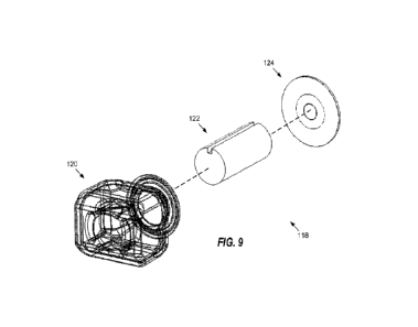
[055] FIG. 9 is an exploded perspective view of the bladder assembly of
FIG. 7B, wherein the
cartridge bladder assembly including a bladder, a wick, and a mesh assembly.
[056] FIG. 10A is a perspective view of a top of the bladder of FIG. 9.
[057] FIG. 10B is a perspective view of the top and a front of the bladder
of FIG. 9.
[058] FIG. 10C is a perspective view of the front of the bladder of FIG. 9.
[059] FIG. 10D is a perspective view of a first side the bladder of FIG. 9.
[060] FIG. 10E is a perspective view of the top and the first side the
bladder of FIG. 9.
[061] FIG. 11A is the view of FIG. 10A illustrated only with shading.
[062] FIG. 11B is the view of FIG. 10B illustrated only with shading.
[063] FIG. 11C is the view of FIG. 10C illustrated only with shading.
[064] FIG. 11D is the view of FIG. 10D illustrated only with shading.
[065] FIG. 11E is the view of FIG. 10E illustrated only with shading.
[066] FIG. 12A is a perspective view illustrated only with shading of the
bladder of FIG. 9.
[067] FIG. 12B is a perspective view illustrated only with shading of the
bladder and the wick of
FIG. 9.
7
CA 03197266 2023- 5- 2
WO 2022/098802
PCT/US2021/057963
[068] FIG. 13A is a top plan view of the wick of FIG. 9.
[069] FIG. 13B is aside elevational view of the wick of FIG. 9, wherein a
longitudinal
channel of the wick is shown.
[070] FIG. 13C is a perspective view of the top and the side of the wick of
FIG. 9, wherein the
longitudinal channel of the wick is shown.
[071] FIG. 13D is a perspective view of a bottom and the side of the wick
of FIG. 9, wherein
the longitudinal channel of the wick is shown.
[072] FIG. 14A is atop plan view of the mesh assembly of FIG. 9, wherein
electrical connections
are omitted for clarity.
[073] FIG. 14B is a perspective view of the top and a side of the mesh
assembly of FIG. 14A.
[074] FIG. 14C is a perspective view of -the side and a bottom of the mcsh
assembly of FIG. 14A.
[075] FIG. 14D is a bottom plan view of the mesh assembly of FIG. 14A.
[076] FIG. 15 is a perspective view of the handheld base assembly of FIG.
1B.
[077] FIG. 16 is the perspective view of the handheld base assembly of FIG.
15, wherein the skin
and tail are omitted.
[078] FIG. 17A is a front elevational view of the handheld base assembly of
FIG. 16.
[079] FIG. 17B is a rear elevational view of the handheld base assembly of
FIG. 16.
[080] FIG. 17C is atop plan view of the handheld base assembly of FIG. 16.
[081] FIG. 17D is an elevational view of a first side of the handheld base
assembly of FIG. 16.
[082] FIG. 17E is a bottom plan view of the handheld base assembly of FIG.
16.
[083] FIG. 17F is an elevational view of a second, opposite side of the
handheld base assembly
of FIG. 16.
[084] FIG. 18 is the perspective view of FIG. 16, wherein the chassis is
further omitted.
[085] FIG. 19A is a partial, cross-sectional view of a distal end of the
front of the handheld base
assembly of FIG. 16.
[086] FIG. 19B is another partial, cross-sectional view of the distal end
of the front of the handheld
base assembly of FIG. 16.
[087] FIG. 19C is a partial view of the distal end of the front of the
handheld base assembly of
FIG. 16 similar to that of FIG. 19 B, but not in cross-section.
[088] FIG. 20A is a perspective view of the metal plate of FIG. 6B.
[089] FIG. 20B is a perspective view of the printed circuit board of FIG.
7A.
[090] FIG. 20C is a front elevational view of the cartridge and printed
circuit board, wherein
the cartridge is transparently shown.
[091] FIG. 21 is a view of disassembled components of a cartridge assembly
of a prototype
commercial embodiment of the invention.
[092] FIG. 22 is a perspective view of the bladder of the cartridge
assembly of FIG. 21.
8
CA 03197266 2023- 5-2
WO 2022/098802
PCT/US2021/057963
[093] FIG. 23 is a perspective view of the bladder of FIG. 22 positioned
within the cartridge of
FIG. 21.
[094] FIG. 24A is an elevational view of a top of a prototype commercial
embodiment of the
invention.
[095] FIG. 24B is an elevational view of a top of a prototype commercial
embodiment of the
invention, wherein -WAVE" is being displayed on a display.
[096] FIG. 24C is an elevational view of the top of the prototype
commercial embodiment of the
invention, wherein a dose count of 97 is being displayed on the display.
[097] FIG. 24D is a perspective partial view of the prototype commercial
embodiment while a
vapor is emitted from the mouthpiece.
[098] FIG. 24E is a perspective view of the prototype commercial embodiment
as an upward
force is applied to the cartridge assembly using two fingers while the base
assembly is held by the
remaining fingers of a hand.
[099] FIG. 24F is a perspective view of the prototype commercial embodiment
following the
application of the upward force FIG. 24E, wherein the cartridge assembly has
been decoupled and
removed from the handheld base assembly.
[0100] FIG. 24G is a view of the prototype commercial embodiment
wherein the decoupled
cartridge assembly has been inverted to show a bottom thereof.
[0101] FIG. 25 is a perspective view of another prototype
commercial embodiment of a preferred
commercial system and apparatus for dosing by patients.
DETAILED DESCRIPTION
[0102] As a preliminary matter, it will readily be understood by
one having ordinary skill in the
relevant art (-Ordinary Artisan") that the invention has broad utility and
application. Furthermore, any
embodiment discussed and identified as being "preferred- is considered to be
part of a best mode
contemplated for carrying out the invention_ Other embodiments also may be
discussed for additional
illustrative purposes in providing a full and enabling disclosure of the
invention. Furthermore, an
embodiment of the invention may incorporate only one or a plurality of the
aspects of the invention
disclosed herein; only one or a plurality of the features disclosed herein; or
combination thereof. As such,
many embodiments are implicitly disclosed herein and fall within the scope of
what is regarded as the
invention.
[0103] Accordingly, while the invention is described herein in
detail in relation to one or more
embodiments, it is to be understood that this disclosure is illustrative and
exemplary of the invention and
is made merely for the purposes of providing a full and enabling disclosure of
the invention. The detailed
disclosure herein of one or more embodiments is not intended, nor is to be
construed, to limit the scope of
patent protection afforded the invention in any claim of a patent issuing here
from, which scope is to be
defined by the claims and the equivalents thereof It is not intended that the
scope of patent protection
9
CA 03197266 2023- 5-2
WO 2022/098802
PCT/US2021/057963
afforded the invention be defined by reading into any claim a limitation found
herein that does not
explicitly appear in the claim itself.
[0104] Thus, for example, any sequence(s) and/or temporal order of
steps of various processes or
methods that are described herein are illustrative and not restrictive.
Accordingly, it should be understood
that, although steps of various processes or methods may be shown and
described as being in a sequence
or temporal order, the steps of any such processes or methods are not limited
to being carried out in any
particular sequence or order, absent an indication otherwise. Indeed, the
steps in such processes or
methods generally may be carried out in various different sequences and orders
while still falling within
the scope of the invention. Accordingly, it is intended that the scope of
patent protection afforded the
invention be defined by the issued claim(s) rather than the description set
forth herein.
[0105] Additionally, it is important to note that each term used
herein refers to that which the
Ordinary Artisan would understand such term to mean based on the contextual
use of such term herein.
To the extent that the meaning of a term used herein¨as understood by the
Ordinary Artisan based on the
contextual use of such term¨differs in any way from any particular dictionary
definition of such term, it
is intended that the meaning of the term as understood by the Ordinary Artisan
should prevail.
[0106] With regard to the construction of the scope of any claim
in the United States, no claim
element is to be interpreted under 35 U.S.C. 112(f) unless the explicit phrase
"means for" or "step for" is
actually used in such claim element, whereupon this statutory provision is
intended to and should apply in
the interpretation of such claim element. With regard to any method claim
including a condition
precedent step, such method requires the condition precedent to be met and the
step to be performed at
least once but not necessarily every time during performance of the claimed
method.
[0107] Furthermore, it is important to note that, as used herein,
"comprising" is open-ended insofar
as that which follows such term is not exclusive. Additionally, -a" and -an"
each generally denotes at
least one- but does not exclude a plurality unless the contextual use dictates
otherwise. Thus, reference to
"a picnic basket having an apple" is the same as "a picnic basket comprising
an apple" and "a picnic
basket including an apple", each of which identically describes "a picnic
basket having at least one apple"
as well as "a picnic basket having apples"; the picnic basket further may
contain one or more other items
beside an apple. In contrast, reference to "a picnic basket having a single
apple" describes "a picnic
basket having only one apple"; the picnic basket further may contain one or
more other items beside an
apple. In contrast, "a picnic basket consisting of an apple" has only a single
item contained therein, i.e.,
one apple; the picnic basket contains no other item.
[0108] When used herein to join a list of items. "or" denotes "at
least one of the items" but does not
exclude a plurality of items of the list. Thus, reference to "a picnic basket
having cheese or crackers"
describes -a picnic basket having cheese without crackers", -a picnic basket
having crackers without
cheese", and "a picnic basket having both cheese and crackers"; the picnic
basket further may contain one
or more other items beside cheese and crackers.
CA 03197266 2023- 5-2
WO 2022/098802
PCT/US2021/057963
[0109] When used herein to join a list of items, "and" denotes
"all of the items of the list". Thus,
reference to "a picnic basket having cheese and crackers" describes "a picnic
basket having cheese,
wherein the picnic basket further has crackers", as well as describes -a
picnic baskct having crackers,
wherein the picnic basket further has cheese"; the picnic basket further may
contain one or more other
items beside cheese and crackers.
[0110] The phrase -at least one" followed by a list of items
joined by -and" denotes an item of the
list but does not require every item of the list. Thus, "at least one of an
apple and an orange"
encompasses the following mutually exclusive scenarios: there is an apple but
no orange; there is an
orange but no apple; and there is both an apple and an orange. In these
scenarios if there is an apple,
there may be more than one apple, and if there is an orange, there may be more
than one orange.
Moreover, the phrase "one or more" followed by a list of items joined by "and"
is the equivalent of "at
least one" followed by the list of items joined by "and".
[0111] Referring now to the drawings, one or more preferred
embodiments in accordance with one
or more aspects and features of the invention are next described. The
following description of one or
more preferred embodiments is merely exemplary in nature and is in no way
intended to limit the
invention, its implementations, or uses.
[0112] In accordance with electronic devices of the invention, a
vibrating mesh is provided for
aerosolizing a liquid without smoldering. The aerosolized liquid preferably is
in the form of a vapor
cloud similar to what a person or observer would surmise to be "vapor" when
vaping. In the context of
vaping, such preferred devices of the invention therefore are believed to
produce an aerosol that is free of
undesired carcinogens. This is in stark contrast to vaporizers used today to
aerosolize e-liquids by heating
the e-liquids and desired compounds contained therein ( e.g., nicotine) or
supplements such as B12,
THC/CBD and other drugs or stimulants. As a result of using heating to
aerosolize the e-liquids, these
vaporizers produce toxic byproducts like formaldehyde, a recognized Group 1
carcinogen for cancer,
which toxic byproducts then are unfortunately inhaled by a person using the
vaporizer. For example,
when the liquids are heated, the liquids undergo a thermochemical reaction
producing unwanted
emissions. The unwanted emissions of the toxic byproducts may cause bodily
harm from extended
inhalation exposure.
[0113] By utilizing a vibrating mesh, preferred electronic devices
in accordance with one or more
aspects and features of the invention produce an aerosol without using heat
and thus advantageously
avoid such toxic byproducts created by the vaporizes currently on the market.
The electronic devices
thereby advantageously produce a carcinogen free aerosol free of harmful
emission byproducts.
[0114] The preferred electronic devices in accordance with one or
more aspects and features of the
invention are particularly well suited for aerosolizing a liquid for
inhalation without heating and, in
particular, for aerosolizing an aqueous formulation including nicotine for
inhalation without heating.
11
CA 03197266 2023- 5-2
WO 2022/098802
PCT/US2021/057963
[0115] Such a preferred embodiment of an electronic device is
illustrated in and described with
reference to FIG. lA through FIG. 20C in accordance with one or more aspect
and features of the
invention. Components for a prototype cartridge assembly arc seen in FIGS. 21,
22, and 23. A
commercial prototype is seen in FIGS. 24A through 24G.
[0116] Other forms of an electronic device in accordance with the
present invention include
vapes, vape pens, and nebulizers. Other terminology may be given to electronic
devices of the present
invention. In any event, electronic devices of the present invention produce
an aerosol for inhalation
without smoldering or heating, whatever commercial or consumer name may be
given.
[0117] FIG. lA illustrates an electronic device 100 having a
handheld base assembly 102 and a
cartridge assembly 104, in accordance with one or more preferred
implementations of the invention. The
cartridge assembly and handheld base assembly are configured to removably
couple together. FIG. 1B
illustrates the act of separating the handheld base assembly 102 from the
cartridge assembly 104 in the
electronic device of FIG. 1A. Preferably, the cartridge assembly magnetically
mounts onto an end of the
handheld base assembly for magnetic, decoupling attachment. FIG. 1C
illustrates a close-up view of the
cartridge assembly 104 after being separated from the handheld base assembly
as illustrated in FIG. 1B.
[0118] With regard to FIGS. 2A-2F, FIG. 2A illustrates a front
elevational view of the cartridge
assembly 104 of FIG. 1C; FIG. 2B illustrates a rear elevational view of the
cartridge assembly 104 of
FIG. 1C; FIG. 2C illustrates a perspective view of the rear and a bottom of
the cartridge assembly
104 of FIG. 1C; FIG. 2D illustrates a perspective view of the bottom of the
cartridge assembly 104 of
FIG. IC; FIG. 2E illustrates a perspective view of the bottom and a first side
of the cartridge
assembly 104 of FIG. 1C; and FIG. 2F illustrates a perspective view of the
first side of the cartridge
assembly 104 of FIG. 1C.
[0119] With regard to FIGS. 3A-3F, FIG. 3A illustrates a
perspective view of the first side and
a top of the cartridge assembly 104 of FIG. 1C; FIG. 3B illustrates a
perspective view of the top of
the cartridge 104 of FIG. 1C; FIG. 3C illustrates a perspective view of the
top and a second side of
the cartridge assembly 104 of FIG. 1C; FIG. 3D illustrates a perspective view
of the second side of
the cartridge assembly 104 of FIG. 1C; FIG. 3E illustrates a perspective view
of the second side and
the bottom of the cartridge assembly 104 of FIG. 1C; and FIG. 3F illustrates a
perspective view of
the front, first side, and top of the cartridge assembly 104 of FIG. 1C.
[0120] The cartridge assembly 104 comprises a mouthpiece 106; and
a cartridge 108. FIG. 4A is
an exploded view of the cartridge assembly 104 of FIG. 1C, wherein two
fasteners 103,105 and the
mouthpiece 106 are illustrated being separated from the cartridge 108.
Additionally, FIG. 4B is a
perspective view of a top and a rear of a mouthpiece 106 of the cartridge
assembly 104 of FIG. 4A; and
FIG. 4C is an elevational view of the rear of the mouthpiece 106 of FIG. 4B.
[0121] FIG. 5A is an elevational view of a front of the cartridge
108 of the cartridge assembly
of FIG. IC. Additionally, FIG. 5B is a perspective view of the front and a top
of the cartridge 108 of
12
CA 03197266 2023- 5-2
WO 2022/098802
PCT/US2021/057963
FIG. 1C; and FIG. 5C is an exploded perspective view of the front, top, and a
first side of the
cartridge 108 of FIG. 1C, wherein an 0-ring 110 and D-ring 112 are removed
from the cartridge
108. An airflow channel is defined between the port of the mouthpiece and a
pressure sensor located
within the handheld base assembly, and the D-ring preferably is provided to
seal the interface between the
cartridge and the mouthpiece to prevent loss of suction along the airflow
channel. The airflow channel is
defined by openings in the mouthpiece, the cartridge, the printed circuit
board, the metal plate, and the
chassis. Furthermore, while one opening is shown in connection with the
mouthpiece in the drawings,
three openings preferable are provided that are equally spaced around the 0-
ring.
[0122] FIG. 6A is a perspective view of the top and front of the
cartridge 108 of FIG. 1C.
wherein the 0-ring 112 and D-ring 110 have been removed from remainder of the
cartridge 108.
Additionally, FIG. 6B is an exploded perspective view of the top, front, and
the first side the
cartridge 108 of FIG. 1C, wherein two fasteners 111,113 and a metal plate 114
are being separated
from the remainder of the cartridge 108. The metal plate 114 is used to couple
the cartridge
assembly 104 to one or more magnets located in a distal end 140 of the base
assembly 102. FIG. 6C
is a perspective view of the top, side, and a rear of the cartridge 108 of
FIG. 6B, wherein the two
fasteners 111,113 and metal plate 114 have been removed from the remainder of
the cartridge 108.
[0123] FIG. 7A is an exploded perspective view of the top, rear,
and first side of the cartridge
108 of FIG. 6C, wherein a circuit board 116 is removed from the remainder of
the cartridge 108.
The cartridge assembly 104 comprises a bladder assembly 118; and FIG. 7B is an
exploded perspective
view of the top, rear, and first side of the cartridge 108 of FIG. 7A, wherein
a bladder assembly 118
is removed from the cartridge 108.
[0124] FIG. 8A is a perspective view of a front of the remainder
of the cartridge 108 of FIG.
7B after the bladder assembly 118 has been removed. Additionally, FIG. 8B is a
perspective view of
the front and a first side of the remainder of the cartridge 108 of FIG. 8A;
and FIG. 8C is a
perspective view of a rear of the remainder of the cartridge 108 of FIG 8A.
[0125] The bladder assembly 118 comprises a bladder 120; a wick
122 contained within the
bladder 120; and a mesh assembly 124. FIG. 9 is an exploded perspective view
of the bladder
assembly 118 of FIG. 7B. The mesh assembly 124 preferably is disposed on top
of a lip of a mouth of
the bladder 120, the bladder 120 extending through an opening in the cartridge
108 to define the mouth.
[0126] FIG. 10A is a perspective view of a top of the bladder 120
of FIG. 9. Additionally, FIG.
10B is a perspective view of the top and a front of the bladder 120 of FIG. 9;
FIG. 10C is a perspective
view of the front of the bladder 120 of FIG. 9; FIG. 10D is a perspective view
of a first side the bladder
120 of FIG. 9; and FIG. 10E is a perspective view of the top and the first
side the bladder 120 of FIG. 9.
[0127] For purposes of further illustration, FIG. 11A is the view
of FIG. 10A illustrated only with
shading; FIG. 11B is the view of FIG. 10B illustrated only with shading; FIG.
11C is the view of FIG.
13
CA 03197266 2023- 5-2
WO 2022/098802
PCT/US2021/057963
10C illustrated only with shading; FIG. 11D is the view of FIG. 10D
illustrated only with shading; and
FIG. 11E is the view of FIG. 10E illustrated only with shading.
[0128] FIG. 12A is a perspective view illustrated only with
shading of the bladder 120 of FIG. 9.
[0129] FIG. 12B is a perspective view illustrated only with
shading of the bladder 120 and the
wick 122 of FIG. 9.
[0130] The wick 122 of the bladder assembly 118 preferably
comprises a lengthwise channel 126.
FIG. 13A is atop plan view of the wick 122 of FIG. 9; FIG. 13B is a side
elevational view of the wick
122 of FIG. 9, wherein a longitudinal channel 126 of the wick 122 is shown;
FIG. 13C is a
perspective view of the top and the side of the wick 122 of FIG. 9, wherein
the longitudinal channel
126 of the wick 122 also is shown; and FIG. 13D is a perspective view of a
bottom and the side of the
wick 122 of FIG. 9, wherein the longitudinal channel 126 of thc wick 122 again
is shown. The
channel 126 preferably extends between distal ends of the wick 122 and
preferably is an open ended
channel at both ends, as shown in these figures. The wick may be rigid and the
lengthwise channel that
extends between its opposite ends assists in delivery liquid to the mesh
assembly for aerosolizing.
[0131] FIG. 14A is atop plan view of the mesh assembly 124 of FIG.
9, wherein electrical
connections are omitted for clarity. FIG. 14B is a perspective view of the top
and a side of the mesh
assembly 124 of FIG. 14A; FIG. 14C is a perspective view of the side and a
bottom of the mesh assembly
124 of FIG. 14A; and FIG. 14D is a bottom plan view of the mesh assembly 124
of FIG. 14A.
[0132] The mesh assembly 124 comprises a mesh material and a
piezoelectric material;
preferably, the mesh assembly 124 comprises a piezo mesh disk. Opening cross
sections of the mesh that
is in contact with the liquid preferably are smaller than the opening cross
sections that face the
mouthpiece and exit of the aerosolized liquid. The taper angle and size of the
perforated mesh preferably
is adjusted during manufacture via electro-forming methods so as to achieve a
laminar and non-turbulent
aerosol that is best suited for deep lung penetration and will, therefore, not
yield large amounts of buccal
deposition. The mesh material is configured to vibrate when the piezoelectric
material is actuated,
whereby an aerosol is produced when the mesh material contacts a liquid of the
bladder 120 such that the
aerosol may be inhaled through the mouthpiece 106. The wick 122 acts to draw
liquid from the bladder
120 to the mesh assembly 124. The wick 122 preferably is retained in constant
physical contact with the
mesh assembly 124. In particular, an end of the wick 122 preferably is secured
by the protuberances of
the bladder extending from the walls proximate a bottom of the bladder, and
the wick has a length such
that a distal end of the wick 122 is maintained in contact with the mesh
assembly when the bladder
assembly 118 is assembled, the opposite end of the wick 122 being held in
place by the protuberances of
the bladder 120.
[0133] In greater detail, the wick 122 is retained in physical
engagement with the bladder 120
proximate its bottom by protuberances that extend from the walls of the
bladder. There are preferably
four protuberances that surround the end of the wick 122 in a discontinuous
circular pattern and receive
14
CA 03197266 2023- 5-2
WO 2022/098802
PCT/US2021/057963
the end of the wick 122 in frictional fit with each of four sides. The wick
122 extends therefrom to and is
retained in physical engagement with the mesh assembly 124 and, in particular,
a piezoelectric disk
having a mesh material which, when powered by the power source, vibrates so as
to aerosolize a liquid
contained within the bladder 120 and conveyed in the wick 122. The mesh
assembly 124 is held in
tension on top of a lip of the mouth of the bladder 120 by a sealing 0-ring
(see, e.g., FIG. 21, 0-ring 212)
that is forced into engagement with the mesh assembly 124 by the attachment of
the mouthpiece 108.
[0134] Screws are preferably utilized in effecting the attachment
whereby the force by which the
0-ring is held in contact with the mesh assembly may be adjusted. A spacer on
a printed circuit board of
the cartridge assembly may additionally engage the bottom of the silicone
bladder and hold the wick in
tension therethrough. Due to these features, it is believed that the bladder
and wick ensure that the mesh
remains in constant contact with the liquid for consistent acrosolization each
time the electronic device is
triggered. The liquid preferably is supplied to the vibrating mesh at a
generally constant pressure
whereby a generally uniform aerosol is produced, and this is accomplished
regardless of the
orientation of the electronic device.
[0135] During a preferred manufacture of the disposable cartridge
assembly, the bladder is filled
with a liquid by injection after assembly of the disposable cartridge
assembly. Since the bladder
preferably is a self-sealing silicone bladder, when the injector needle is
removed, the bladder re-seals and
no liquid drains or leaks out. In this aspect, the liquid may be injected as a
last stop via an access
port/injector port that is located on the bottom of the cartridge.
Alternatively, the bladder is inserted into
the cartridge and then is filled with liquid first (top-down pour) without
utilizing a needle or puncturing
the bladder with an injector needle. In this manner, the bladder is filled by
pouring liquid into the bladder
and, once the desired volume has been dispensed, the wick is inserted inside
the bladder and then the
bladder is capped off by the mesh assembly and the rest of the disposable
cartridge assembly is then
assembled.
[0136] The handheld base assembly 102 comprises circuitry; and a
power supply for actuating the
mesh assembly 124 when the base assembly 102 and cartridge assembly 104 are
coupled together,
preferably through the pins that engage electrical contacts when the base
assembly 102 and cartridge
assembly 104 are coupled. One or more of the pins further are provided for
electronic communication
between circuitry of the handheld base assembly 102 and non-transitory machine-
readable memory
located within the cartridge assembly 104.
[0137] FIG. 15 is a perspective view of the handheld base
assembly 102 of FIG. 1B.
[0138] FIG. 16 is the perspective view of the handheld base
assembly 102 of FIG. 15, wherein the
skin 132 and tail 134 are omitted.
[0139] FIG. 17A is a front elevational view of the handheld base
assembly 102 of FIG. 16; FIG.
17B is a rear elevational view of the handheld base assembly 102 of FIG. 16;
FIG. 17C is a top plan view
of the handheld base assembly 102 of FIG. 16; FIG. 17D is an elevational view
of a first side of the
CA 03197266 2023- 5-2
WO 2022/098802
PCT/US2021/057963
handheld base assembly 102 of FIG. 16; FIG. 17E is a bottom plan view of the
handheld base assembly
102 of FIG. 16; and FIG. 17F is an elevational view of a second, opposite side
of the handheld base
assembly 102 of FIG. 16.
[0140] FIG. 18 is the perspective view of the handheld base
assembly 102 of FIG. 16, wherein the
chassis 136 is further omitted.
[0141] FIG. 19A is a partial, cross-sectional view of a distal end
140 of the front of the handheld
base assembly of FIG. 16; FIG. 19B is another partial, cross-sectional view of
the distal end 140 of the
front of the handheld base assembly of FIG. 16; and FIG_ 19C is a partial view
of the distal end 140 of the
front of the handheld base assembly of FIG. 16 similar to that of FIG. 19 B,
but not in cross-section.
[0142] FIG. 20A is a perspective view of the metal plate 114 of
FIG. 6B; FIG. 20B is a perspective
view of the printed circuit board 116 of FIG. 7A; and FIG. 20C is a front
elevational view of the
cartridge 108 and printed circuit board 116, wherein the cartridge 108 is
transparently shown.
[0143] FIG. 21 is a view of disassembled components of a cartridge
assembly 204 of a
prototype commercial embodiment 200 of the invention.
[0144] FIG. 22 is a perspective view of the bladder 220 of the
cartridge assembly 204 of FIG.
21.
[0145] FIG. 23 is a perspective view of the bladder 220 of FIG. 22
positioned within the
cartridge 204 of FIG. 21.
[0146] With regard to a prototype commercia embodiment, FIG. 24A
is an elevational view of a
top of the prototype commercial embodiment 200. Additionally, FIG. 24B is an
elevational view of a top
of a prototype commercial embodiment 200, wherein -WAVE" is being displayed on
a display; and FIG.
24C is an elevational view of the top of the prototype commercial embodiment
200, wherein a dose count
of 97 is being displayed on the display. FIG. 24D is a perspective partial
view of the prototype
commercial embodiment 200 while a vapor is emitted from the mouthpiece. FIG.
24E is a perspective
view of the prototype commercial embodiment 200 as an upward force is applied
to the cartridge
assembly 204 using two fingers while the base assembly 202 is held by the
remaining fingers of a hand.
FIG. 24F is a perspective view of the prototype commercial embodiment 200
following the application of
the upward force of FIG. 24E, wherein the cartridge assembly 204 has been
decoupled and removed from
the handheld base assembly 202. FIG. 24G is a view of the prototype commercial
embodiment 200,
wherein the decoupled cartridge assembly 204 has been inverted to show a
bottom thereof.
[0147] FIG. 25 is a perspective view of another prototype
commercial embodiment intended for use
in a preferred commercial system and apparatus for dosing by patients.
Preferably, in such system and
apparatus, the disposable cartridge assembly 254 of the electronic device 250
comprises a printed circuit
board or other electronic circuitry 256, and the disposable cartridge assembly
communicates with
electronic circuitry 258 contained in the handheld base assembly 250 when
coupled therewith. Circuitry
258 preferably supports the capabilities of the disposable cartridge assembly
as well as manages the
16
CA 03197266 2023- 5-2
WO 2022/098802
PCT/US2021/057963
OLED display 260, recharging of the power source through USB port 264, and
operation of the button
262.
[0148] Preferably, the printed circuit board or other electronic
circuitry 256 includes non-transitory
machine-readable memory, such as flash memory, that includes information
regarding the liquid
contained in the bladder and dosing information related thereto, e.g., the
number of doses dispensed so far
from the disposable cartridge assembly. The disposable cartridge assembly
further may be configured or
programmed to only work with one or more specified handheld base assemblies to
the exclusion of other
handheld base assemblies. In this respect, each handheld base assembly may
include a unique identifier
or other information, such as an encryption key, in non-transitory machine-
readable memory, such as
read-only memory, as part of the electronic circuitry 258. Thus, for example,
a disposable cartridge
assembly could be configured to work only with a handheld base assembly of a
particular person, e.g., a
certain patient for whom a prescription is provided via the disposable
cartridge assembly, to whom the
handheld base assembly has been specifically programmed or configured. A
plurality of disposable
cartridge assemblies then may be provided to the patient over time as part of
a subscription/prescription,
in-home delivery system for continuity of care, especially in chronic disease
management, wherein each
disposable cartridge assembly is configured to work only with the handheld
base assembly specifically
programmed or configured for that specific patient and no other.
[0149] The electronic device 250 preferably comprises a breath-
actuated, accurate, and efficient
metered-dose delivery system. A haptic engine is provided for customizable
haptic vibration to signal the
end of precisely metered dose. The haptic feedback thus provides a biofeedback
loop that preferably is
customizable through a mobile app via wireless communication or communication,
such as Bluetooth, or
via the USB-port used for recharging the power source. The communications also
provide a means for
compliance check as well as provides accessible, real-time electronic medical
record (EMR) data for
providers, clinicians, and patients. Such communications further enable
cartridge tracking, monitoring,
user authentication, and geo-fencing capabilities for an increase standard of
care and patience outcomes_
[0150] In the system using the electronic device 250 disclosed in
FIG. 25, the patient's inhalation
through a pressure sensor triggers the vibrating mesh to activate under normal
use. Bluetooth-enabled
mobile app integration logs precise dosing data in real-time, which is easily
accessed by the patient and
clinician. An OLED display visually indicates data to the patient including,
for example, dose count, and
displays intelligent prompts to the patient. The disposable cartridge assembly
monitoring and memory
capabilities further provide lifecycle, tamper-proof and chain of custody
compliance from manufacture to
delivery.
[0151] Based on the foregoing description, it will be readily
understood by those persons skilled
in the art that the invention has broad utility and application. Electronic
devices of the invention can be
utilized to deliver liquids comprising supplements, drugs, or therapeutically
effective amounts of
pharmaceuticals using an aerosol having particles of a size that can easily be
inhaled. The aerosol can
17
CA 03197266 2023- 5-2
WO 2022/098802
PCT/US2021/057963
be used, for example, by a patient within the bounds of an inhalation therapy,
whereby the liquid
containing a supplement, therapeutically effective pharmaceutical, or drug
reaches the patient's
respiratory tract upon inhalation. Desired compounds such as nicotine,
flavoring, and supplements like
B12, can be received by a person through inhalation without the toxic
byproducts like formaldehyde¨a
recognized Group 1 Carcinogen for caner¨that is currently being created during
heating in
conventional vapes. Electronic devices of the invention further can be used in
the marijuana industries,
but only where legal, for delivery of cannabinoids and CBD oils and the like.
Moreover, many
embodiments and adaptations of the invention other than those specifically
described herein, as well as
many variations, modifications, and equivalent arrangements, will be apparent
from or reasonably
suggested by the invention and the foregoing descriptions thereof, without
departing from the substance
or scope of the invention.
[0152] It further will be appreciated from the foregoing that at
least some preferred embodiments of
the invention represent a portable, orientation-agnostic vibrating mesh
nebulizer. It further will be
appreciated from the foregoing that at least some preferred embodiments emit
an aerosol that is¨
sensorially speaking¨equivalent to vapor, i.e., not a mist but instead that
which is generated by
traditional vapes, thereby providing an enjoyable consumer product for those
who are accustomed to
vaping.
[0153] Accordingly, while the invention has been described herein
in detail in relation to one or
more preferred embodiments, it is to be understood that this disclosure is
only illustrative and exemplary
of the invention and is made merely for the purpose of providing a full and
enabling disclosure of the
invention. The foregoing disclosure is not intended to be construed to limit
the invention or otherwise
exclude any such other embodiments, adaptations, variations, modifications or
equivalent arrangements,
the invention being limited only by the claims appended hereto and the
equivalents thereof
18
CA 03197266 2023- 5-2