Note: Descriptions are shown in the official language in which they were submitted.
CA 03197653 2023-03-30
WO 2022/079037
PCT/EP2021/078198
Aerosol generator for an inhalation device
Technical Field of the Invention
The present invention relates to an aerosol generator for an inhalation
device, in particular a vibrating
mesh nebulizer.
Background
Aerosols for medical inhalation therapy generally comprise an active
ingredient dissolved or
suspended in an aerosolisable liquid (often water). A homogeneous distribution
of aerosol droplets
with a droplet size of around 5 p.m is required in order to reach deep into
the lungs. Vibrating mesh
nebulizers are one type of device for producing such aerosols. These devices
comprise a vibrator, such
as piezoelectric element which is excited at ultrasonic frequencies in order
to induce vibration; a
membrane (sometimes called a mesh), which has a large number of micro-pores
(i.e. through holes)
which typically have a diameter of 1 p.m to 10 p.m; and a reservoir, which
supplies the liquid drug
formulation to the membrane. Such nebulizers typically have a piezoelectric
element ("piezo") in the
form of an annular ring, with one electrical contact (e.g. positive) on its
upper surface and the other
electrical contact (e.g. negative) on its lower surface.
Many vibrating mesh nebulizers have an annular piezo with the membrane
arranged over the central
hole. The membrane is either directly attached to the piezo, or the mesh and
the piezo are both
attached to a supporting substrate, such as a planar metal ring. The piezo
expands and contracts
radially in response to an applied voltage, thereby flexing the membrane,
directly, or via the substrate.
Such nebulizers are disclosed, for example, in US 2003/047620, US 9027548, WO
2012/046220 and
WO 2015/193432. US 2010/0044460 discloses a vibrating mesh nebulizer that
operates in a different
manner. The piezo is attached to a flange located towards one end of a
transducer, and the membrane
is attached to the other end. The piezo causes the transducer to vibrate
longitudinally, which in turn
passes the vibrations on to the membrane. Thus the membrane vibrates in a
longitudinal "piston"
mode, instead of being flexed by radial vibration of the piezo. In each type
of vibrating mesh nebulizer,
a voltage is applied across the piezo by means of two electrical contacts, one
on each side. For
example, a metal substrate may form the contact on one side, and a pin may
contact a conductive
layer applied to the other side. Each contact has a wire or other connector,
such as a flexible strip
connector, for connection to the source of electrical power. This type of
arrangement necessitates a
1
CA 03197653 2023-03-30
WO 2022/079037
PCT/EP2021/078198
number of different components. US 2019/329281 discloses a nebulizer of the
first type, in which the
two electrical contacts to the piezo are located on the on the same surface.
Brief Description of the Invention
The present inventors have identified an improved way of arranging the
electrical contacts to the piezo
in an aerosol generator. In a first aspect, the present invention provides an
aerosol generator
comprising a vibratable membrane, a support member, an annular piezoelectric
element having a first
surface with a first conductive region, a second surface with a second
conductive region, an inner edge
and an outer edge. The second conductive region extends across at least part
of the inner edge or the
outer edge onto the first surface of the piezoelectric element to form a
contact region. The first
conductive region and the contact region are spaced apart on the first
surface. The aerosol generator
further comprises a flexible connector having a surface which is an electrical
insulator with first and
second conductive regions that correspond to the first conductive region and
to the contact region on
the piezoelectric element respectively. The flexible connector has two 'S'
shaped legs for making
electrical connection to a controller that provides a driving current to the
piezoelectric element.
The term "S-shaped" means that the legs have two bends, curves or corners
which are in opposite
senses. The bends/curves/corners may be such that the legs lie in the plane of
the flexible connector.
Alternatively, the bends/curves/corners may be such that the legs are arranged
out of the plane of
the flexible connector.
The second conductive region on the piezoelectric element may extend across
part of the outer edge
or across part of the inner edge to form the contact region on the first
surface. The second conductive
region on the piezoelectric element may extend across the whole of the outer
edge or the whole of
the inner edge to form the contact region.
The first and second conductive regions may cover most of the first and the
second surfaces of the
piezoelectric element respectively.
The piezoelectric element may be connected to the flexible connector by a
layer of anisotropic
conducting paste or by anisotropic conductive adhesive transfer tape.
The conductive regions on the piezoelectric element may be stencilled silver
layers.
2
CA 03197653 2023-03-30
WO 2022/079037
PCT/EP2021/078198
The support member of the aerosol generator may comprise a hollow tubular body
having a flange at,
or close to, a first end, onto which the piezoelectric element is attached,
and a second end into or
onto which the membrane is mounted. Alternatively, the support member may
comprise an
essentially planar annulus or disk, and the membrane may be in contact with
the piezoelectric
element, or the membrane and the piezoelectric element may be mounted on the
support member,
for example on opposite sides of the support member.
In a second aspect, the present invention provides an inhalation device
comprising the aerosol
generator of the first aspect of the invention. The inhalation device may
comprise an aerosol head
comprising the aerosol generator; a base unit having one or more an air inlet
openings, an air outlet
opening, and a groove; and a mouthpiece component which is insertable into the
groove and which
has an air inlet opening that is attachable to the air outlet opening of the
base unit, a lateral opening
for receiving the aerosol generator, and an aerosol outlet opening; wherein
the base unit, the
mouthpiece component and the aerosol head are detachably connectible with each
other.
Brief Description of the Figures
Figure 1 shows an expanded view of a known aerosol generator.
Figures 2A and 28 show the piezo used in the aerosol generator of Figure 1.
Figure 3 shows an expanded view of an aerosol generator according to the
invention.
Figures 4A and 48 show the electrical contacts on a piezo for use in the
aerosol generator of Figure 3.
Figure 5 shows a flexible connector for use with the piezo of Figure 4.
Figure 6 shows a cross-section through the interface between the piezo and the
flexible connector in
the aerosol generator of Figure 3.
Figures 7A and 78 show a further flexible connector for use with the piezo of
Figure 4.
Figures 8A and 88 show a second configuration of the electrical contacts on a
piezo.
Figure 9 shows a flexible connector used with the piezo of Figure 8.
Figures 10A and 1013 show a third configuration of the electrical contacts on
a piezo.
Figures 11A and 118 show a fourth configuration of the electrical contacts on
a piezo.
Figure 12 shows an expanded view of a vibrating membrane nebulizer device
which uses an aerosol
generator according to the invention.
3
CA 03197653 2023-03-30
WO 2022/079037
PCT/EP2021/078198
Detailed Description of the Invention
Figure 1 shows an expanded view of a known aerosol generator of the type
disclosed in US
2010/0044460. The aerosol generator 1 has a transducer 2 formed from a hollow
tubular stainless
steel body 4 with a flange 3 having a larger wall thickness which acts as a
stress concentration zone
towards one end. The membrane 5, which has a large number of holes with
openings in the range
from about 1 p.m to about 10 pm, is mounted on or just inside the other end of
the tubular body. The
internal volume of the tubular body forms a reservoir into which the liquid to
be nebulized is filled.
The transducer 2 is designed so that small vibrations of the piezo 6 are
amplified into larger vibrations
of the membrane 5. The piezo 6 is an annular single or multilayer ceramic and
is thicker than the piezos
typically used in aerosol generators in which the membrane is directly in
contact with the piezo (or
only spaced apart by an essentially planar substrate). The stress
concentration zone 3 has a relatively
large mass. When the piezo 6 is actuated, it vibrates longitudinally, i.e. in
a direction parallel to the
symmetry axis of the transducer 2, causing micronic displacements of the
flange. These are amplified
by the tubular body 4 of the transducer and cause the membrane 5 to vibrate in
a longitudinal mode,
typically at a frequency in the range of 50 to 200 kHz range. Vibration of the
membrane leads to the
formation and emission of aerosol droplets through the holes. The membrane may
be made of plastic,
silicon, ceramic or more preferably metal, and may be affixed at or near to
the end of the transducer
by various means, such as gluing, brazing, crimping or laser welding.
Figures 2A and 2B show the upper 8 lower 7 and surfaces of the piezo 6
respectively. A conductive
silver stencil layer 15 covers the lower surface 7, apart from uncoated
regions 19a at the inner edge
17 and 19b at the outer edge 18. Similarly, a second conductive silver stencil
layer 16 covers the upper
surface 8, apart from the uncoated regions 19a, 19b. The silver stencil layers
15, 16 form the two
electrical contacts, and the uncoated regions 19a, 19b prevent a short circuit
between the contacts.
First 9 and second 10 flexible electrical connectors abut the lower 7 and
upper surfaces 8 of the piezo
respectively. The connectors each have a leg 11, 12, through which electrical
connection is made to a
printed circuit board (PCB). The connectors are bonded to the piezo with a
conductive adhesive, for
example anisotropic conductive film (ACF); the second connector 10 (and hence
the piezo) is also
bonded to the lower side of the flange 3, for example by epoxy glue 13. The
connectors form an
electrical connection to the silver layers through the conductive adhesive, so
that an electric field can
be applied across the piezo.
4
CA 03197653 2023-03-30
WO 2022/079037
PCT/EP2021/078198
In the configuration shown in Figure 1, the second flexible connector 10 is
located between the piezo
6 and the flange 3. Thus the second flexible connector 10 could absorb some of
the mechanical energy
from the piezo, and hence damp the vibrations. This can be avoided by an
alternative configuration in
which the second flexible connector 10 is located on the other side of the
flange 3, so that the piezo
6 is attached directly to the flange. In this alternative configuration, the
electrical connection from the
second flexible connector 10 to the upper side of the piezo 8 is made though
the flange 3 (which is
metallic). However, it is necessary to form a good electrical and mechanical
connection between the
flange 3 and the upper surface 8 of the piezo 6, which can be difficult to
achieve.
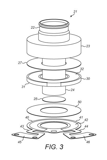
Figure 3 shows an expanded view of an aerosol generator 21 according to the
invention, which is
similar to that of Figure 1. The transducer 22 has a flange 23 to which the
piezo 30 is attached, for
example by epoxy glue 27, and a tubular body 24 with a membrane 25 at its end,
as in Figure 1.
However, in Figure 3, there is only one flexible connector 40, which abuts the
lower surface 31 of the
piezo 30. The upper surface 32 of the piezo 30 is bonded directly to the lower
side of the flange 23.
The flexible connector 40 has an annular contact part 41 with an upper surface
42 and two legs 43, 44
through which electrical connection is made to a PCB at the feet 45, 46. It is
bonded to the piezo by a
layer of anisotropic conducting paste 50 (ACP).
Figures 4A and 4B show the upper 32 and lower 31 surfaces of the piezo
respectively. First and second
conductive silver stencil layers 33, 34 cover most of the lower (first)
surface 31 and the upper (second)
32 surface respectively. There is an uncoated region 35a at the inner edge 36
of the piezo, as in Figures
2A and 2B. Another uncoated region 35b occupies most of the outer edge 37.
However, in contrast to
Figures 2A and 2B, there is a detour 35c in the uncoated region 35b away from
the outer edge 37 on
the lower surface 31, so that the first conductive layer 33 has a narrow part
39. The second conductive
layer 34 correspondingly extends across part of the outer edge 37a and onto
the lower surface to form
a small contact region 38 defined by the detour 35c. The uncoated detour 35c
separates the contact
region 38 from the first conductive layer 33 so that current cannot flow
directly between the first and
second conductive layers.
Figure 5 shows the upper surface 42 of the flexible connector 40, which, when
assembled in the
aerosol generator, faces the lower surface of the piezo. The surface layer of
the connector 40 is an
electrical insulator (such as polyimide), apart from two conductive regions
47, 48 formed for example
from gold-coated copper. These regions respectively correspond to the
locations of the first
conductive layer 33 and the small contact region 38 of the second conductive
layer on the piezo. The
5
CA 03197653 2023-03-30
WO 2022/079037
PCT/EP2021/078198
conductive regions 47, 48 connect to a PCB via tracks inside each leg 43, 44
which terminate in a
contact point on each foot 45, 46. The legs lie in the same plane as the
annular contact part 41 and
are S-shaped (when viewed from above), which makes them more flexible. This
decouples the piezo
from the fixed connections between the feet 45, 46 of the flexible connector
and the PCB. This
minimizes damping of the transducer vibrations by the flexible connector,
which would otherwise
reduce the aerosol output rate from the membrane.
Figure 6 shows a cross-section through the interface between the small contact
region 38 on the lower
surface 31 of the piezo and the conductive region 48 on the upper surface 42
of the flexible connector,
between which is a layer of anisotropic conducting paste 50. The ACP contains
conductive particles in
a non-conductive binder. When heat and pressure is applied, a thin layer 51 of
ACP is formed between
the contact region 38 and the conductive region 48; a thicker layer 52 is
formed where there is no
conductive region on the flexible connector. The thin layer 51 is sufficiently
thin that the conductive
particles in the ACP span the gap between the contact region 38 and the
conductive region 48, and
hence form an electrical connection. (A thin layer is similarly formed between
the other conductive
regions 33, 47). However, the thicker layer 52 is wider than the size of the
conductive particles, so the
particles remain isolated from each other within the non-conductive binder.
Thus there is no electrical
connection through the thicker layer 52, which prevents short circuits. The
flexible connector could
alternatively be attached to the piezo in other ways that prevent short
circuits, for example by using
.. a non-conductive glue and appropriate masks.
Figures 7A & 7B show a second embodiment of a flexible connector 60 for use
with the piezo of Figures
4A and 4B. Figure 7A shows the upper surface 62 of the flexible connector 60,
which, when assembled
in the aerosol generator, faces the lower surface of the piezo. The surface
layer of the connector 60 is
an electrical insulator (such as polyimide), apart from two conductive regions
67, 68 formed, for
example, from gold-coated copper. These regions respectively correspond to the
locations of the first
conductive layer 33 and the small contact region 38 of the second conductive
layer on the piezo, but
are arranged in a different way from the flexible connector of Figure 5. The
first conductive region 67
is in the form of a complete ring situated towards the inner edge of the
annular contact part 61, so
that it is in contact with the first conductive layer 33, and does not come
into contact with the small
contact region 38. It connects to the first track 69 which runs along the
first leg 63. The second
conductive region 68 is in the form of a small circle (similar to the second
conductive region 48 in
Figure 5), and connects to the second track 70 which runs along the second leg
64. The tracks 69, 70
on each leg 63, 64 terminate in a contact point on each foot 65, 66, which is
connected to the PCB as
6
CA 03197653 2023-03-30
WO 2022/079037
PCT/EP2021/078198
before. Figure 7B shows the flexible connector in a perspective view from
below (so that its upper
surface is not visible). The legs 63, 64 are bent out of the plane of the
annular contact part 61, and are
S-shaped when viewed from the side. Thus the S shape lies in a different plane
compared to the
flexible connector of Figure 5, but nonetheless increases the flexibility of
the legs in a similar manner.
This decouples the piezo from the fixed connections between the feet 65, 66 of
the flexible connector
and the PCB, which minimizes damping of the transducer vibrations by the
flexible connector.
Figures 8A and 8B show an alternative configuration of the conductive silver
stencil layers 133,134 on
the piezo. This is similar to the embodiment of Figures 4A and 4B, except that
the detour 135c is
formed in the uncoated region 135a at the inner edge 136 (rather than the
outer edge 137). The
second conductive layer 134 covers most of the upper surface 132 and also
extends across part of the
inner edge 136a and onto the lower surface to form a small contact region 138.
As shown in Figure 9,
the two conductive regions 147, 148 on the upper surface 142 of the flexible
connector 140 are shaped
to correspond to the first conductive layer 133 and the small contact region
138 on the piezo.
Figures 10A and 10B show a variant of the embodiment of Figures 4A and 4B in
which there is an
uncoated region 235a at the inner edge 236 of the piezo as before, but the
uncoated region 235b is
located at a short distance onto the lower surface 231 around the whole of the
outer edge 237. The
second conductive layer 234 extends over the whole of the outer edge 237 and
onto the lower surface
231 to form an annular contact region 238. Figures 11A and 11B show a variant
of the embodiment of
Figures 8A and 8B in which there is an uncoated region 335a at the outer edge
337 of the piezo as
before, but the uncoated region 335b is located at a short distance onto the
lower surface 331 around
the whole of the inner edge 336. The second conductive layer 334 extends over
the whole of the inner
edge 336 and onto the lower surface 331 to form an annular contact region 338.
In each case, the two
conductive regions on the upper surface of the flexible connector (not shown)
are shaped to
correspond to the conductive layers 233, 238 and 333, 338 on the piezo
respectively.
Having both contacts on this same side of the piezo has the advantage that a
single connector with
both the positive and negative connections can be used, instead of two
connectors as in known
aerosol generators. Thus fewer components are required, which reduces the cost
and simplifies the
assembly process. Having fewer components also improves the reliability and
lifetime of the aerosol
generator because it removes potential points of failure.
7
CA 03197653 2023-03-30
WO 2022/079037
PCT/EP2021/078198
It would be possible to simply have two connections on one side of the piezo
with no conductive region
on the other side. However, this would result in reduced membrane vibration
and hence poor
performance, because the electrical field applied between the contacts would
not properly activate
all of the piezo. In the present invention, the conductive layers cover almost
all of the surfaces, so the
electrical field is applied uniformly across the whole piezo. This results in
uniform deformation of the
piezo, and hence good membrane vibration, whilst still reaping the benefits of
having fewer
components. Also, maximizing the area of the contact on the piezo minimizes
the resistance arising
from the contact.
While the configurations of contacts shown in Figures 4A & 4B, 8A & 8B, 10A &
1013 and 11A & 116 all
work well, the configuration of Figures 4A & 4B is preferred. This is because
it is simpler to produce a
conductive layer that wraps over a small region of the outer edge of the piezo
than either a layer that
wraps over part or all of the inner edge (as in Figures 8A & 8B and 11A &
116), or around the whole,
or a large part of, the outer edge (as in Figures 10A & 10B).
While the invention has been described with reference to an aerosol generator
of the type described
in US 2010/0044460, in which the membrane is spaced apart from the piezo by a
tubular transducer
body, it can also be used in aerosol generators of the types described in US
2003/047620, US 9027548,
WO 2012/046220 and WO 2015/193432, in which the membrane is directly in
contact with the piezo,
or only spaced apart by an essentially planar support member.
Nonetheless, the invention is especially advantageous in aerosol generators of
the type described in
US 2010/0044460, because damping arising from the connectors is a particular
concern in these. Since
the transducer amplifies small vibrations of the piezo into larger vibrations
of the membrane, any
damping of the small vibrations would also be amplified. This would result in
reduced membrane
vibration, and hence a reduced aerosol output rate. Replacing two flexible
connectors with a single
flexible connector avoids the need to either interpose a flexible connector
between the piezo and the
flange (which causes damping) or to form an electrical, as well as mechanical
connection between the
piezo and the flange (which can be difficult to achieve).
Figure 12 shows an expanded view of a vibrating membrane nebulizer device
which is described in
detail in EP2724741 and W02013/098334, and which uses an aerosol generator of
the type described
in US 2010/0044460. The device comprises three parts: a base unit 60, a
mouthpiece component 70,
and an aerosol head 80. The base unit 60 has one or more air inlet opening(s),
an air outlet opening
8
CA 03197653 2023-03-30
WO 2022/079037
PCT/EP2021/078198
62, a groove 63 for receiving the mouthpiece component 70, and one or more key
lock members 64.
The base unit contains an electronic controller which controls the operation
of the nebulizer. The
mouthpiece component 70 has an air inlet opening 71 which is attachable to the
air outlet opening 62
of the base unit 60, a lateral opening 72 for receiving the aerosol generator
21, and an aerosol outlet
opening 73. A mixing channel 75 extends from the air inlet opening 71 to the
aerosol outlet opening
73. The mouthpiece 70 is insertable into the groove 63 of the base unit 60.
The aerosol head 80 has
the aerosol generator 21, a filling chamber 82 for the liquid drug formulation
to be nebulized, which
is in fluid contact with the upper end of the aerosol generator 21, and one or
more key lock members
83 complementary to the key lock members 64 of the base unit 60. A lid 84
closes the upper end of
the filling chamber 82 and prevents contamination or spillage of the liquid
during use. The base unit
60, the mouthpiece 70 and the aerosol head 80 are detachably connectible with
one another. The
device is assembled by inserting the mouthpiece component 70 into the groove
63 in the base unit
60, then placing the aerosol head 80 over the mouthpiece component 70 and
engaging the key lock
member(s) 83 of the aerosol head 80 with the complementary member(s) 64 of the
base unit 60 by
gentle pressure on both the aerosol head and the base unit. The aerosol
generator 21 is positioned in
the aerosol head 80 in such a way that when engaging the key lock member(s),
the aerosol generator
21 is inserted into the lateral opening 72 of the mouthpiece 70. This creates
airtight connections
between the aerosol generator 21 and the lateral opening 72 in the mouthpiece
as well as between
the air outlet opening 62 of the base unit 60 and the air inlet opening 71 of
the mouthpiece 70. The
base unit 60, the mouthpiece 70 and the aerosol head 80 can be separated by
reversing these steps.
Example
Aerosol generators as shown in Figure 3 were assembled using the piezo of
Figures 4A & 4B. These
were tested with saline solution, and were found to produce good aerosol
output rates, similar to
those produced by the aerosol generator shown in Figure 1. Thus the aerosol
generator of the
invention produces comparable performance to the known aerosol generator, but
has fewer
components and is simpler to manufacture.
9