Note: Descriptions are shown in the official language in which they were submitted.
WO 2022/109712
PCT/CA2021/050560
Filtering Channel Responses for Motion Detection
CROSS-REFERENCE TO RELATED APPLICATIONS
[0001] This application claims priority to U.S. Patent Application
No. 17/106,989, filed
November 30, 2020, entitled "Filtering Channel Responses for Motion
Detection," the
disclosure of which is hereby incorporated by reference.
BACKGROUND
[0002] The following description relates to filtering channel
responses for motion
detection.
[0003] Motion detection systems have been used to detect movement, for
example, of
objects in a room or an outdoor area. In some example motion detection
systems, infrared
or optical sensors are used to detect movement of objects in the sensor's
field of view.
Motion detection systems have been used in security systems, automated control
systems,
and other types of systems.
DESCRIPTION OF DRAWINGS
[0004] FIG. 1 is a diagram showing an example wireless communication system.
[0005] FIGS. 2A-2B are diagrams showing example wireless signals communicated
between wireless communication devices.
[0006] FIG. 2C is a diagram showing an example wireless sensing system
operating to
detect motion in a space.
[0007] FIG. 3 is a diagram showing example signal paths in a wireless
communication
system.
[0008] FIG. 4 is a plot showing an example time-domain filter
representation of a
propagation environment.
[0009] FIG. 5 is a schematic diagram of an example signal processing system
for a
motion detection system.
1
CA 03198277 2023- 5- 10
WO 2022/109712
PCT/CA2021/050560
[0010] FIG. 6A is a plot showing an example time-domain channel response hi(t)
obtained from an observed frequency-domain channel response Hi(f).
[0011] FIG. 6B is a plot showing an example filtered time-domain channel
response
[4(0 obtained from a first iteration of the example signal processing system
shown in FIG.
S.
[0012] FIG. 6C is a plot showing an example updated time-domain channel
response
(t) obtained in a second iteration of the example signal processing system
shown in FIG.
S.
[0013] FIGS. 7A, 7C, and 7E are plots showing example error signals
Ei(f).
[0014] FIGS. 7B, 7D, and 7F are plots showing example time-domain pulses that
correlate with the error signals E(f) shown in FIGS. 7A, 7C, and 7E,
respectively.
[0015] FIG. 8 is a plot showing an example observed frequency-domain channel
response Hi(f) and an example reconstructed frequency-domain channel response
ili(f)
obtained using the example signal processing system shown in FIG. S.
[0016] FIG. 9 is a flowchart showing an example process for
filtering channel responses
for motion detection.
[0017] FIG. 10 is a block diagram showing an example wireless communication
device.
DETAILED DESCRIPTION
[0018] In some aspects of what is described here, a wireless sensing system
can process
wireless signals (e.g., radio frequency signals) transmitted through a space
between
wireless communication devices for wireless sensing applications. Example
wireless
sensing applications include detecting motion, which can include one or more
of the
following: detecting motion of objects in the space, motion tracking,
localization of motion
in a space, breathing detection, breathing monitoring, presence detection,
gesture
detection, gesture recognition, human detection (e.g., moving and stationary
human
detection), human tracking, fall detection, speed estimation, intrusion
detection, walking
detection, step counting, respiration rate detection, sleep pattern detection,
sleep quality
monitoring, apnea estimation, posture change detection, activity recognition,
gait rate
2
CA 03198277 2023- 5- 10
WO 2022/109712
PCT/CA2021/050560
classification, gesture decoding, sign language recognition, hand tracking,
heart rate
estimation, breathing rate estimation, room occupancy detection, human
dynamics
monitoring, and other types of motion detection applications. Other examples
of wireless
sensing applications include object recognition, speaking recognition,
keystroke detection
and recognition, tamper detection, touch detection, attack detection, user
authentication,
driver fatigue detection, traffic monitoring, smoking detection, school
violence detection,
human counting, metal detection, human recognition, bike localization, human
queue
estimation, Wi-Fi imaging, and other types of wireless sensing applications.
For instance,
the wireless sensing system may operate as a motion detection system to detect
the
existence and location of motion based on Wi-Fi signals or other types of
wireless signals.
[0019] The examples described herein may be useful for home monitoring. In
some
instances, home monitoring using the wireless sensing systems described herein
may
provide several advantages, including full home coverage through walls and in
darkness,
discreet detection without cameras, higher accuracy and reduced false alerts
(e.g., in
comparison with sensors that do not use Wi-Fi signals to sense their
environments), and
adjustable sensitivity. By layering Wi-Fi motion detection capabilities into
routers and
gateways, a robust motion detection system may be provided.
[0020] The examples described herein may also be useful for wellness
monitoring.
Caregivers want to know their loved ones are safe, while seniors and people
with special
needs want to maintain their independence at home with dignity. Wellness
monitoring
using the wireless sensing systems described herein provide a solution that
uses wireless
signals to detect motion without using cameras or infringing on privacy,
generates alerts
when unusual activity is detected, tracks sleep patterns, and generates
preventative health
data. For example, caregivers can monitor motion, visits from health care
professionals,
and unusual behavior such as staying in bed longer than normal. Furthermore,
motion is
monitored unobtrusively without the need for wearable devices, and the
wireless sensing
systems described herein offer a more affordable and convenient alternative to
assisted
living facilities and other security and health monitoring tools.
[0021] The examples described herein may also be useful for setting up a smart
home.
In some examples, the wireless sensing systems described herein use predictive
analytics
3
CA 03198277 2023- 5- 10
WO 2022/109712
PCT/CA2021/050560
and artificial intelligence (AI), to learn motion patterns and trigger smart
home functions
accordingly. Examples of smart home functions that may be triggered include
adjusting the
thermostat when a person walks through the front door, turning other smart
devices on or
off based on preferences, automatically adjusting lighting, adjusting HVAC
systems based
on present occupants, etc.
[0022] In some aspects of what is described here, a set of observed
channel responses
are obtained based on a set of wireless signals transmitted through a space
(or propagation
environment). Each of the wireless signals in the set of wireless signals that
is transmitted
in the environment may be an orthogonal frequency division multiplexing (OFDM)
signal,
which can include, for example, a PHY frame. The PHY frame can, in some
instances, include
one or more Legacy PHY fields, one or more MIMO training fields, or both.
Example Legacy
PHY fields include a Legacy Long Training Field (L-LTF), a Legacy Short
Training Field (L-
STF), and other types of Legacy PHY fields. Example MIMO training fields
include a High
Efficiency Long Training Field (HE-LTF), a Very High-Throughput Long Training
Field
(VHT-LTF), a High-Throughput Long Training Field (HT-LTF), and other types of
MIMO
training fields. The fields in the PHY frames of the wireless signals in the
set of wireless
signals can be used to obtain the set of observed channel responses. In some
instances, the
set of observed channel response includes frequency-domain channel responses,
and each
frequency-domain channel response in the set of frequency-domain channel
responses may
correspond to a respective wireless signal in the set of wireless signals.
[0023] Motion of an object in the space can cause a change in one or more of
the
frequency-domain channel responses, and changes observed in the set of
frequency-
domain channel responses can be used to detect motion of an object within the
space. In
some instances, changes in the set of frequency-domain channel responses can
be caused
by device- or system-level impairments (e.g., noise or distortions) that are
not related to
changes in the physical environment (e.g., motion of an object in the space).
For example,
electronic impairments on the device-level or the system-level (or both) may
cause a
change in the set of frequency-domain channel responses. Therefore,
impairments that are
not related to changes in the physical environment (e.g., motion) can corrupt
the set of
frequency-domain channel responses. Consequently, motion detection errors
(e.g., one or
4
CA 03198277 2023- 5- 10
WO 2022/109712
PCT/CA2021/050560
more false positives) can occur when motion of an object in the space is
detected using the
corrupted set of frequency-domain channel responses.
[0024] In some aspects of what is described here, each frequency-domain
channel
response from the set of observed frequency-domain channel responses is
processed to
filter out noise or distortions that are not related to changes in the
physical environment. A
result of the filtering operation is a set of reconstructed frequency-domain
channel
responses. In some aspects of what is described here, the filtering operation
also generates
a set of quality metrics, and each quality metric corresponds to a respective
reconstructed
frequency-domain channel response and a respective observed frequency-domain
channel
response. In some instances, the quality metric may be a measure of an extent
to which the
respective observed frequency-domain channel response has been corrupted by
impairments that are not related to changes in the physical environment.
Therefore, the
quality metric may be analogous to a signal-to-noise ratio (SNR) of the
corresponding
frequency-domain channel response. In some aspects of what is described here,
motion is
detected based on the set of observed frequency-domain channel responses. For
example,
motion can be detected by detecting changes in the set of reconstructed
frequency-domain
channel responses. In another example, motion can be detected by detecting
changes in the
set of observed frequency-domain channel responses when each of the quality
metrics are
greater than a predetermined threshold.
[0025] In some instances, aspects of the systems and techniques
described here provide
technical improvements and advantages over existing approaches. The systems
and
techniques described here can be used to increase the accuracy of a motion
detection
system. For example, the false positive rate of a motion detection system can
be reduced by
filtering out the effects of device- or system-level electronic impairments on
the observed
frequency-domain channel responses and by taking the quality metrics into
account when
detecting motion. The technical improvements and advantages achieved in
examples
where the wireless sensing system is used for motion detection may also be
achieved in
other examples where the wireless sensing system is used for other wireless
sensing
applications.
CA 03198277 2023- 5- 10
WO 2022/109712
PCT/CA2021/050560
[0026] In some instances, a wireless sensing system can be
implemented using a
wireless communication network. Wireless signals received at one or more
wireless
communication devices in the wireless communication network may be analyzed to
determine channel information for the different communication links (between
respective
pairs of wireless communication devices) in the network. The channel
information may be
representative of a physical medium that applies a transfer function to
wireless signals that
traverse a space. In some instances, the channel information includes a
channel response.
Channel responses can characterize a physical communication path, representing
the
combined effect of, for example, scattering, fading, and power decay within
the space
between the transmitter and receiver. In some instances, the channel
information includes
beamforming state information (e.g., a feedback matrix, a steering matrix,
channel state
information (CSI), etc.) provided by a beamforming system. Beamforming is a
signal
processing technique often used in multi antenna (multiple-input/multiple-
output
(MIMO)) radio systems for directional signal transmission or reception.
Beamforming can
be achieved by operating elements in an antenna array in such a way that
signals at
particular angles experience constructive interference while others experience
destructive
interference.
[0027] The channel information for each of the communication links may be
analyzed
by one or more motion detection algorithms (e.g., running on a hub device, a
client device,
or other device in the wireless communication network, or on a remote device
communicably coupled to the network) to detect, for example, whether motion
has
occurred in the space, to determine a relative location of the detected
motion, or both. In
some aspects, the channel information for each of the communication links may
be
analyzed to detect whether an object is present or absent, e.g., when no
motion is detected
in the space.
[0028] In some instances, a motion detection system returns motion data. In
some
implementations, motion data is a result that is indicative of a degree of
motion in the
space, the location of motion in the space, a time at which the motion
occurred, or a
combination thereof. In some instances, the motion data can include a motion
score, which
may include, or may be, one or more of the following: a scalar quantity
indicative of a level
6
CA 03198277 2023- 5- 10
WO 2022/109712
PCT/CA2021/050560
of signal perturbation in the environment accessed by the wireless signals; an
indication of
whether there is motion; an indication of whether there is an object present;
or an
indication or classification of a gesture performed in the environment
accessed by the
wireless signals.
[0029] In some implementations, the motion detection system can be implemented
using one or more motion detection algorithms. Example motion detection
algorithms that
can be used to detect motion based on wireless signals include the techniques
described in
U.S. Patent No. 9,523,760 entitled "Detecting Motion Based on Repeated
Wireless
Transmissions," U.S. Patent No. 9,584,974 entitled "Detecting Motion Based on
Reference
Signal Transmissions," U.S. Patent No. 10,051,414 entitled "Detecting Motion
Based On
Decompositions Of Channel Response Variations," U.S. Patent No. 10,048,350
entitled
"Motion Detection Based on Groupings of Statistical Parameters of Wireless
Signals," U.S.
Patent No. 10,108,903 entitled "Motion Detection Based on Machine Learning of
Wireless
Signal Properties," U.S. Patent No. 10,109,167 entitled "Motion Localization
in a Wireless
Mesh Network Based on Motion Indicator Values," U.S. Patent No. 10,109,168
entitled
"Motion Localization Based on Channel Response Characteristics," U.S. Patent
No.
10,743,143 entitled "Determining a Motion Zone for a Location of Motion
Detected by
Wireless Signals," U.S. Patent No. 10,605,908 entitled "Motion Detection Based
on
Beamforming Dynamic Information from Wireless Standard Client Devices," U.S.
Patent No.
10,605,907 entitled "Motion Detection by a Central Controller Using
Beamforming Dynamic
Information," U.S. Patent No. 10,600,314 entitled "Modifying Sensitivity
Settings in a
Motion Detection System," U.S. Patent No. 10,567,914 entitled "Initializing
Probability
Vectors for Determining a Location of Motion Detected from Wireless Signals,"
U.S. Patent
No. 10,565,860 entitled "Offline Tuning System for Detecting New Motion Zones
in a
Motion Detection System," U.S. Patent No. 10,506,384 entitled "Determining a
Location of
Motion Detected from Wireless Signals Based on Prior Probability," U.S. Patent
No.
10,499,364 entitled "Identifying Static Leaf Nodes in a Motion Detection
System," U.S.
Patent No. 10,498,467 entitled "Classifying Static Leaf Nodes in a Motion
Detection
System," U.S. Patent No. 10,460,581 entitled "Determining a Confidence for a
Motion Zone
Identified as a Location of Motion for Motion Detected by Wireless Signals,"
U.S. Patent No.
7
CA 03198277 2023- 5- 10
WO 2022/109712
PCT/CA2021/050560
10,459,076 entitled "Motion Detection based on Beamforming Dynamic
Information," U.S.
Patent No. 10,459,074 entitled "Determining a Location of Motion Detected from
Wireless
Signals Based on Wireless Link Counting," U.S. Patent No. 10,438,468 entitled
"Motion
Localization in a Wireless Mesh Network Based on Motion Indicator Values,"
U.S. Patent No.
10,404,387 entitled "Determining Motion Zones in a Space Traversed by Wireless
Signals,"
U.S. Patent No. 10,393,866 entitled "Detecting Presence Based on Wireless
Signal Analysis,"
U.S. Patent No. 10,380,856 entitled "Motion Localization Based on Channel
Response
Characteristics," U.S. Patent No. 10,318,890 entitled "Training Data for a
Motion Detection
System using Data from a Sensor Device," U.S. Patent No. 10,264,405 entitled
"Motion
Detection in Mesh Networks," U.S. Patent No. 10,228,439 entitled "Motion
Detection Based
on Filtered Statistical Parameters of Wireless Signals," U.S. Patent No.
10,129,853 entitled
"Operating a Motion Detection Channel in a Wireless Communication Network,"
U.S. Patent
No. 10,111,228 entitled "Selecting Wireless Communication Channels Based on
Signal
Quality Metrics," and other techniques.
[0030] FIG. 1 illustrates an example wireless communication system
100. The wireless
communication system 100 may perform one or more operations of a motion
detection
system. The technical improvements and advantages achieved from using the
wireless
communication system 100 to detect motion are also applicable in examples
where the
wireless communication system 100 is used for another wireless sensing
application.
[0031] The example wireless communication system 100 includes three wireless
communication devices 102A, 102B, 102C. The example wireless communication
system
100 may include additional wireless communication devices 102 and/or other
components
(e.g., one or more network servers, network routers, network switches, cables,
or other
communication links, etc.).
[0032] The example wireless communication devices 102A, 102B, 102C can operate
in a
wireless network, for example, according to a wireless network standard or
another type of
wireless communication protocol. For example, the wireless network may be
configured to
operate as a Wireless Local Area Network (WLAN), a Personal Area Network
(PAN), a
metropolitan area network (MAN), or another type of wireless network. Examples
of
WLANs include networks configured to operate according to one or more of the
802.11
8
CA 03198277 2023- 5- 10
WO 2022/109712
PCT/CA2021/050560
family of standards developed by IEEE (e.g., Wi-Fi networks), and others.
Examples of
PANs include networks that operate according to short-range communication
standards
(e.g., BLUETOOTHC), Near Field Communication (NFC), ZigBee), millimeter wave
communications, and others.
[0033] In some implementations, the wireless communication devices 102A, 102B,
102C may be configured to communicate in a cellular network, for example,
according to a
cellular network standard. Examples of cellular networks include: networks
configured
according to 2G standards such as Global System for Mobile (GSM) and Enhanced
Data
rates for GSM Evolution (EDGE) or EGPRS; 3G standards such as Code Division
Multiple
Access (CDMA), Wideband Code Division Multiple Access (WCDMA), Universal
Mobile
Telecommunications System (UMTS), and Time Division Synchronous Code Division
Multiple Access (TD-SCDMA); 4G standards such as Long-Term Evolution (LTE) and
LTE-
Advanced (LTE-A); SG standards, and others.
[0034] In some cases, one or more of the wireless communication devices 102 is
a Wi-Fi
access point or another type of wireless access point (WAP). In some cases,
one or more of
the wireless communication devices 102 is an access point of a wireless mesh
network,
such as, for example, a commercially-available mesh network system (e.g.,
GOOGLE Wi-Fi,
EERO mesh, etc.). In some instances, one or more of the wireless communication
devices
102 can be implemented as wireless access points (APs) in a mesh network,
while the other
wireless communication device(s) 102 are implemented as leaf devices (e.g.,
mobile
devices, smart devices, etc.) that access the mesh network through one of the
APs. In some
cases, one or more of the wireless communication devices 102 is a mobile
device (e.g., a
smartphone, a smart watch, a tablet, a laptop computer, etc.), a wireless-
enabled device
(e.g., a smart thermostat, a Wi-Fi enabled camera, a smart TV), or another
type of device
that communicates in a wireless network.
[0035] In the example shown in FIG. 1, the wireless communication devices
transmit
wireless signals to each other over wireless communication links (e.g.,
according to a
wireless network standard or a non-standard wireless communication protocol),
and the
wireless signals communicated between the devices can be used as motion probes
to detect
motion of objects in the signal paths between the devices. In some
implementations,
9
CA 03198277 2023- 5- 10
WO 2022/109712
PCT/CA2021/050560
standard signals (e.g., channel sounding signals, beacon signals), non-
standard reference
signals, or other types of wireless signals can be used as motion probes.
[0036] In the example shown in FIG. 1, the wireless communication link between
the
wireless communication devices 102A, 102C can be used to probe a first motion
detection
zone 110A, the wireless communication link between the wireless communication
devices
102B, 102C can be used to probe a second motion detection zone 110B, and the
wireless
communication link between the wireless communication device 102A, 102B can be
used
to probe a third motion detection zone 110C. In some instances, the motion
detection
zones 110 can include, for example, air, solid materials, liquids, or another
medium through
which wireless electromagnetic signals may propagate.
[0037] In the example shown in FIG. 1, when an object moves in any of the
motion
detection zones 110, the motion detection system may detect the motion based
on signals
transmitted through the relevant motion detection zone 110. Generally, the
object can be
any type of static or moveable object, and can be living or inanimate. For
example, the
object can be a human (e.g., the person 106 shown in FIG. 1), an animal, an
inorganic object,
or another device, apparatus, or assembly, an object that defines all or part
of the boundary
of a space (e.g., a wall, door, window, etc.), or another type of object.
[0038] In some examples, the wireless signals propagate through a
structure (e.g., a
wall) before or after interacting with a moving object, which may allow the
object's motion
to be detected without an optical line-of-sight between the moving object and
the
transmission or receiving hardware. In some instances, the motion detection
system may
communicate the motion detection event to another device or system, such as a
security
system or a control center.
[0039] In some cases, the wireless communication devices 102 themselves are
configured to perform one or more operations of the motion detection system,
for example,
by executing computer-readable instructions (e.g., software or firmware) on
the wireless
communication devices. For example, each device may process received wireless
signals to
detect motion based on changes in the communication channel. In some cases,
another
device (e.g., a remote server, a cloud-based computer system, a network-
attached device,
CA 03198277 2023- 5- 10
WO 2022/109712
PCT/CA2021/050560
etc.) is configured to perform one or more operations of the motion detection
system. For
example, each wireless communication device 102 may send channel information
to a
specified device, system, or service that performs operations of the motion
detection
system.
[0040] In an example aspect of operation, wireless communication devices 102A,
102B
may broadcast wireless signals or address wireless signals to the other
wireless
communication device 102C, and the wireless communication device 102C (and
potentially
other devices) receives the wireless signals transmitted by the wireless
communication
devices 102A, 102B. The wireless communication device 102C (or another system
or
device) then processes the received wireless signals to detect motion of an
object in a space
accessed by the wireless signals (e.g., in the zones 110A, 11B). In some
instances, the
wireless communication device 102C (or another system or device) may perform
one or
more operations of a motion detection system.
[0041] FIGS. 2A and 2B are diagrams showing example wireless signals
communicated
between wireless communication devices 204A, 204B, 204C. The wireless
communication
devices 204A, 204B, 204C can be, for example, the wireless communication
devices 102A,
102B, 102C shown in FIG. 1, or may be other types of wireless communication
devices.
[0042] In some cases, a combination of one or more of the wireless
communication
devices 204A, 204B, 204C can be part of, or may be used by, a motion detection
system.
The example wireless communication devices 204A, 204B, 204C can transmit
wireless
signals through a space 200. The example space 200 may be completely or
partially
enclosed or open at one or more boundaries of the space 200. The space 200 can
be or may
include an interior of a room, multiple rooms, a building, an indoor area,
outdoor area, or
the like. A first wall 202A, a second wall 20213, and a third wall 202C at
least partially
enclose the space 200 in the example shown.
[0043] In the example shown in FIGS. 2A and 2B, the first wireless
communication
device 204A transmits wireless motion probe signals repeatedly (e.g.,
periodically,
intermittently, at scheduled, unscheduled, or random intervals, etc.). The
second and third
11
CA 03198277 2023- 5- 10
WO 2022/109712
PCT/CA2021/050560
wireless communication devices 204B, 204C receive signals based on the motion
probe
signals transmitted by the wireless communication device 204A.
[0044] As shown, an object is in a first position 214A at an initial
time (t0) in FIG. 2A,
and the object has moved to a second position 214B at subsequent time (t1) in
FIG. 2B. In
FIGS. 2A and 2B, the moving object in the space 200 is represented as a human,
but the
moving object can be another type of object. For example, the moving object
can be an
animal, an inorganic object (e.g., a system, device, apparatus, or assembly),
an object that
defines all or part of the boundary of the space 200 (e.g., a wall, door,
window, etc.), or
another type of object. In the example shown in FIGS. 2A and 2B, the wireless
communication devices 204A, 204B, 204C are stationary and are, consequently,
at the same
position at the initial time to and at the subsequent time t1. However, in
other examples,
one or more of the wireless communication devices 204A, 204B, 204C can be
mobile and
may move between initial time tO and subsequent time t1.
[0045] As shown in FIGS. 2A and 2B, multiple example paths of the wireless
signals
transmitted from the first wireless communication device 204A are illustrated
by dashed
lines. Along a first signal path 216, the wireless signal is transmitted from
the first wireless
communication device 204A and reflected off the first wall 202A toward the
second
wireless communication device 204B. Along a second signal path 218, the
wireless signal
is transmitted from the first wireless communication device 204A and reflected
off the
second wall 202B and the first wall 202A toward the third wireless
communication device
204C. Along a third signal path 220, the wireless signal is transmitted from
the first
wireless communication device 204A and reflected off the second wall 202B
toward the
third wireless communication device 204C. Along a fourth signal path 222, the
wireless
signal is transmitted from the first wireless communication device 204A and
reflected off
the third wall 202C toward the second wireless communication device 204B.
[0046] In FIG. 2A, along a fifth signal path 224A, the wireless
signal is transmitted from
the first wireless communication device 204A and reflected off the object at
the first
position 214A toward the third wireless communication device 204C. Between
time tO in
FIG. 2A and time t1 in FIG. 2B, the object moves from the first position 214A
to a second
position 214B in the space 200 (e.g., some distance away from the first
position 214A). In
12
CA 03198277 2023- 5- 10
WO 2022/109712
PCT/CA2021/050560
FIG. 2B, along a sixth signal path 224B, the wireless signal is transmitted
from the first
wireless communication device 204A and reflected off the object at the second
position
214B toward the third wireless communication device 204C. The sixth signal
path 224B
depicted in FIG. 2B is longer than the fifth signal path 224A depicted in FIG.
2A due to the
movement of the object from the first position 214A to the second position
214B. In some
examples, a signal path can be added, removed, or otherwise modified due to
movement of
an object in a space.
[0047] The example wireless signals shown in FIGS. 2A and 2B can experience
attenuation, frequency shifts, phase shifts, or other effects through their
respective paths
and may have portions that propagate in another direction, for example,
through the walls
202A, 202B, and 202C. In some examples, the wireless signals are radio
frequency (RF)
signals. The wireless signals may include other types of signals.
[0048] The transmitted signal can have a number of frequency components in a
frequency bandwidth, and the transmitted signal may include one or more bands
within
the frequency bandwidth. The transmitted signal may be transmitted from the
first
wireless communication device 204A in an omnidirectional manner, in a
directional
manner, or otherwise. In the example shown, the wireless signals traverse
multiple
respective paths in the space 200, and the signal along each path can become
attenuated
due to path losses, scattering, reflection, or the like and may have a phase
or frequency
offset.
[0049] As shown in FIGS. 2A and 2B, the signals from various paths 216, 218,
220, 222,
224A, and 224B combine at the third wireless communication device 204C and the
second
wireless communication device 20413 to form received signals. Because of the
effects of the
multiple paths in the space 200 on the transmitted signal, the space 200 may
be
represented as a transfer function (e.g., a filter) in which the transmitted
signal is input and
the received signal is output. When an object moves in the space 200, the
attenuation or
phase offset applied to a wireless signal along a signal path can change, and
hence, the
transfer function of the space 200 can change. When the same wireless signal
is
transmitted from the first wireless communication device 204A, if the transfer
function of
the space 200 changes, the output of that transfer function, e.g. the received
signal, can also
13
CA 03198277 2023- 5- 10
WO 2022/109712
PCT/CA2021/050560
change. A change in the received signal can be used to detect motion of an
object.
Conversely, in some cases, if the transfer function of the space does not
change, the output
of the transfer function - the received signal - may not change.
[0050] FIG. 2C is a diagram showing an example wireless sensing system
operating to
detect motion in a space 201. The example space 201 shown in FIG. 2C is a home
that
includes multiple distinct spatial regions or zones. In the example shown, the
wireless
motion detection system uses a multi-AP home network topology (e.g., mesh
network or a
Self-Organizing-Network (SON)), which includes three access points (APs): a
central access
point 226 and two extension access points 228A, 228B. In a typical multi-AP
home
network, each AP typically supports multiple bands (2.4G, 5G, 6G), and
multiple bands may
be enabled at the same time. Each AP can use a different Wi-Fi channel to
serve its clients,
as this may allow for better spectrum efficiency.
[0051] In the example shown in FIG. 2C, the wireless communication network
includes a
central access point 226. In a multi-AP home Wi-Fi network, one AP may be
denoted as the
central AP. This selection, which is often managed by manufacturer software
running on
each AP, is typically the AP that has a wired Internet connection 236. The
other APs 228A,
228B connect to the central AP 226 wirelessly, through respective wireless
backhaul
connections 230A, 230B. The central AP 226 may select a wireless channel
different from
the extension APs to serve its connected clients.
[0052] In the example shown in FIG. 2C, the extension APs 228A, 228B extend
the range
of the central AP 226, by allowing devices to connect to a potentially closer
AP or different
channel. The end user need not be aware of which AP the device has connected
to, as all
services and connectivity would generally be identical. In addition to serving
all connected
clients, the extension APs 228A, 2288 connect to the central AP 226 using the
wireless
backhaul connections 230A, 230B to move network traffic between other APs and
provide
a gateway to the Internet. Each extension AP 228A, 228B may select a different
channel to
serve its connected clients.
[0053] In the example shown in FIG. 2C, client devices (e.g., Wi-Fi
client devices) 232A,
232B, 232C, 232D, 232E, 232F, 232G are associated with either the central AP
226 or one
14
CA 03198277 2023- 5- 10
WO 2022/109712
PCT/CA2021/050560
of the extension APs 228 using a respective wireless link 234A, 234B, 234C,
234D, 234E,
234F, 234G. The client devices 232 that connect to the multi-AP network may
operate as
leaf nodes in the multi-AP network. In some implementations, the client
devices 232 may
include wireless-enabled devices (e.g., mobile devices, a smartphone, a smart
watch, a
tablet, a laptop computer, a smart thermostat, a wireless-enabled camera, a
smart TV, a
wireless-enabled speaker, a wireless-enabled power socket, etc.).
[0054] When the client devices 232 seek to connect to and associate with their
respective APs 226, 228, the client devices 232 may go through an
authentication and
association phase with their respective APs 226, 228. Among other things, the
association
phase assigns address information (e.g., an association ID or another type of
unique
identifier) to each of the client devices 232. For example, within the IEEE
802.11 family of
standards for Wi-Fi, each of the client devices 232 can identify itself using
a unique address
(e.g., a 48-bit address, an example being the MAC address), although the
client devices 232
may be identified using other types of identifiers embedded within one or more
fields of a
message. The address information (e.g., MAC address or another type of unique
identifier)
can be either hardcoded and fixed, or randomly generated according to the
network
address rules at the start of the association process. Once the client devices
232 have
associated to their respective APs 226, 228, their respective address
information may
remain fixed. Subsequently, a transmission by the APs 226, 228 or the client
devices 232
typically includes the address information (e.g., MAC address) of the
transmitting wireless
device and the address information (e.g., MAC address) of the receiving
device.
[0055] In the example shown in FIG. 2C, the wireless backhaul connections
230A, 230B
carry data between the APs and may also be used for motion detection. Each of
the
wireless backhaul channels (or frequency bands) may be different than the
channels (or
frequency bands) used for serving the connected Wi-Fi devices.
[0056] In the example shown in FIG. 2C, wireless links 234A, 234B,
234C, 234D, 234E,
234F, 234G may include a frequency channel used by the client devices 232A,
232B, 232C,
232D, 232E, 232F, 232G to communicate with their respective APs 226, 228. Each
AP can
select its own channel independently to serve their respective client devices,
and the
wireless links 234 may be used for data communications as well as motion
detection.
CA 03198277 2023- 5- 10
WO 2022/109712
PCT/CA2021/050560
[0057] The motion detection system, which may include one or more motion
detection
or localization processes running on one or more of the client devices 232 or
on one or
more of the APs 226, 228, may collect and process data (e.g., channel
information)
corresponding to local links that are participating in the operation of the
wireless sensing
system. The motion detection system can be installed as a software or firmware
application
on the client devices 232 or on the APs 226, 228, or may be part of the
operating systems of
the client devices 232 or the APs 226, 228.
[0058] In some implementations, the APs 226, 228 do not contain motion
detection
software and are not otherwise configured to perform motion detection in the
space 201.
Instead, in such implementations, the operations of the motion detection
system are
executed on one or more of the client devices 232. In some implementations,
the channel
information may be obtained by the client devices 232 by receiving wireless
signals from
the APs 226, 228 (or possibly from other client devices 232) and processing
the wireless
signal to obtain the channel information. For example, the motion detection
system
running on the client devices 232 can have access to channel information
provided by the
client device's radio firmware (e.g., Wi-Fi radio firmware) so that channel
information may
be collected and processed.
[0059] In some implementations, the client devices 232 send a
request to their
corresponding AP 226, 228 to transmit wireless signals that can be used by the
client
device as motion probes to detect motion of objects in the space 201. The
request sent to
the corresponding AP 226, 228 may be a null data packet frame, a beamforming
request, a
ping, standard data traffic, or a combination thereof. In some
implementations, the client
devices 232 are stationary while performing motion detection in the space 201.
In other
examples, one or more of the client devices 232 can be mobile and may move
within the
space 201 while performing motion detection.
[0060] Mathematically, a signal f (t) transmitted from a wireless
communication device
(e.g., the wireless communication device 204A in FIGS. 2A and 2B or the APs
226, 228 in
FIGS. 2C) may be described according to Equation (1):
16
CA 03198277 2023- 5- 10
WO 2022/109712
PCT/CA2021/050560
09
f (t) = cne-i'mt
(1)
71._ co
where can represents the frequency of nth frequency component of the
transmitted signal,
cõ represents the complex coefficient of the nth frequency component, and t
represents
time. With the transmitted signal f (t) being transmitted, an output signal
rk(t) from a path
k may be described according to Equation (2):
rk(t) = an,kcne1Thr+0.,k)
(2)
77= -00
where cen,k represents an attenuation factor (or channel response; e.g., due
to scattering,
reflection, and path losses) for the nth frequency component along path k, and
ckk
represents the phase of the signal for nth frequency component along path k.
Then, the
received signal R at a wireless communication device can be described as the
summation of
all output signals rk(t) from all paths to the wireless communication device,
which is
shown in Equation (3):
R = rk(t)
(3)
Substituting Equation (2) into Equation (3) renders the following Equation
(4):
R = (cemkeiOn,k)cnejwnt
(4)
k n=-co
[0061] The received signal R at a wireless communication device
(e.g., the wireless
communication devices 204B, 204C in FIGS. 2A and 2B or the client devices 232
in FIGS.
2C) can then be analyzed (e.g., using one or more motion detection algorithms)
to detect
motion. The received signal R at a wireless communication device can be
transformed to
the frequency domain, for example, using a Fast Fourier Transform (FFT) or
another type
of algorithm. The transformed signal can represent the received signal R as a
series of n
complex values, one for each of the respective frequency components (at then
frequencies
can). For a frequency component at frequency can, a complex value 17n may be
represented
as follows in Equation (5):
17
CA 03198277 2023- 5- 10
WO 2022/109712
PCT/CA2021/050560
CP
Yn = CnCrn,k-k
(5) ' =
[0062] The complex value Yll for a given frequency component con indicates a
relative
magnitude and phase offset of the received signal at that frequency component
con. The
signal f (t) may be repeatedly transmitted within a time period, and the
complex value
Yn can be obtained for each transmitted signal f (t). When an object moves in
the space, the
complex value 17-7, changes over the time period due to the channel response
an,k of the
space changing. Accordingly, a change detected in the channel response (and
thus, the
complex value 17-72) can be indicative of motion of an object within the
communication
channel. Conversely, a stable channel response may indicate lack of motion.
Thus, in some
implementations, the complex values K, for each of multiple devices in a
wireless network
can be processed to detect whether motion has occurred in a space traversed by
the
transmitted signals f (t).
[0063] In another aspect of FIGS. 2A, 2B, 2C, beamforming state information
may be
used to detect whether motion has occurred in a space traversed by the
transmitted signals
f (t). For example, beamforming may be performed between devices based on some
knowledge of the communication channel (e.g., through feedback properties
generated by a
receiver), which can be used to generate one or more steering properties
(e.g., a steering
matrix) that are applied by a transmitter device to shape the transmitted
beam/signal in a
particular direction or directions. In some instances, changes to the steering
or feedback
properties used in the beamforming process indicate changes, which may be
caused by
moving objects in the space accessed by the wireless signals. For example,
motion may be
detected by identifying substantial changes in the communication channel, e.g.
as indicated
by a channel response, or steering or feedback properties, or any combination
thereof, over
a period of time.
[0064] In some implementations, for example, a steering matrix may be
generated at a
transmitter device (beamformer) based on a feedback matrix provided by a
receiver device
(beamformee) based on channel sounding. Because the steering and feedback
matrices are
related to propagation characteristics of the channel, these beamforming
matrices change
as objects move within the channel. Changes in the channel characteristics are
accordingly
18
CA 03198277 2023- 5- 10
WO 2022/109712
PCT/CA2021/050560
reflected in these matrices, and by analyzing the matrices, motion can be
detected, and
different characteristics of the detected motion can be determined. In some
implementations, a spatial map may be generated based on one or more
beamforming
matrices. The spatial map may indicate a general direction of an object in a
space relative
to a wireless communication device. In some cases, "modes" of a beamforming
matrix (e.g.,
a feedback matrix or steering matrix) can be used to generate the spatial map.
The spatial
map may be used to detect the presence of motion in the space or to detect a
location of the
detected motion.
[0065] In some implementations, a space through which a set of
wireless signals is
transmitted may be described as a frequency-domain filter that applies a
transfer function
to the set of wireless signals. Changes observed in the frequency-domain
filter over time
can be indicative of motion of an object within the space. FIG. 3 is a diagram
showing
example signal paths in a wireless communication system 300. The example
wireless
communication system 300 shown in FIG. 3 includes wireless communication
devices
302A, 302B. The wireless communication devices 302A, 302B can be, for example,
the
wireless communication devices 102A, 102B shown in FIG. 1, the wireless
communication
devices 204A, 204B, 204C shown in FIGS. 2A and 2B, the devices 226, 228, 232
shown in
FIG. 2C, or they may be other types of wireless communication devices. The
wireless
communication system 300 operates in an environment that includes two
scatterers 310A,
310B. The wireless communication system 300 and its environment may include
additional
or different features.
[0066] In the example shown in FIG. 3, the wireless communication device 302A
transmits a radio frequency (RF) wireless signal, and the wireless
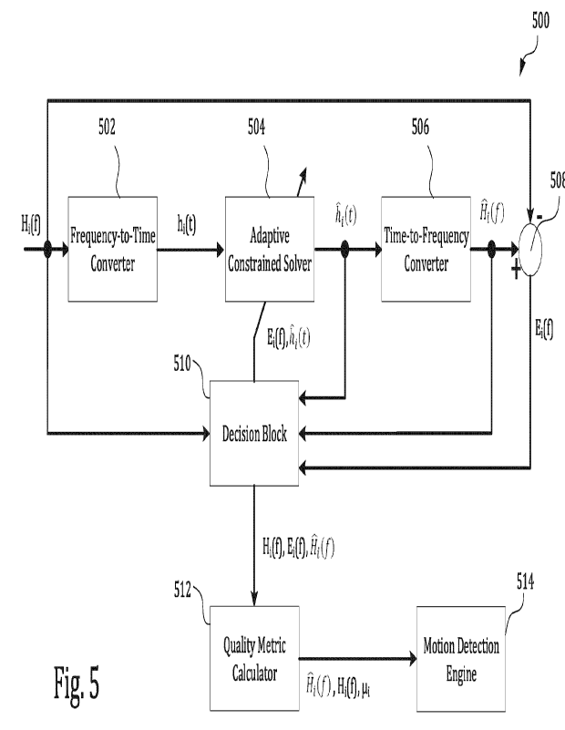
communication device
302B receives the wireless signal. The wireless signal transmitted by the
wireless
communication device 302A may be one of the wireless signals in the set of
wireless signals
transmitted through the environment between the wireless communication devices
302A,
302B. In the environment between the wireless communication devices 302A,
302B, the
wireless signal interacts with the scatterers 310A, 310B. The scatterers 310A,
310B can be
any type of physical object or medium that scatters radio frequency signals,
for example,
part of a structure, furniture, a living object, etc.
19
CA 03198277 2023- 5- 10
WO 2022/109712
PCT/CA2021/050560
[0067] In the example shown in FIG. 3, the wireless signal traverses
a direct signal path
304A and two indirect signal paths 304B, 304C. Along signal path 304B from the
wireless
communication device 302A, the wireless signal reflects off the scatterer 310A
before
reaching the wireless communication device 302B. Along signal path 304C from
the
wireless communication device 302A, the wireless signal reflects off the
scatterer 310B
before reaching the wireless communication device 302B.
[0068] The propagation environment represented by the signal paths shown in
FIG. 3
can be described as a time-domain filter. For instance, the characteristic
response, or
impulse response, of the propagation environment shown in FIG. 3 can be
represented by
the time-domain filter:
3
h(t) = akS(t ¨ Tk)
(6)
In some instances, the time-domain filter h(t) may be referred to as a time-
domain channel
response, since the time-domain filter h(t) is the response of the propagation
environment
to a unit impulse transmitted by wireless communication device 302A at time
t=0. In
Equation (6), the integer k indexes the three signal paths, and the
coefficients ak are
complex phasors that represent the magnitude and phase of the scattering along
each
signal path. The values of the coefficients ak are determined by physical
characteristics of
the environment, for example, free space propagation and the type of
scattering objects
present. In some examples, increasing attenuation along a signal path (e.g.,
by an absorbing
medium like a human body or otherwise) may generally decrease the magnitude of
the
corresponding coefficient ak. Similarly, a human body or another medium acting
as a
scatterer can change the magnitude and phase of the coefficients ak.
[0069] FIG. 4 is a plot 400 showing an example time-domain filter
representation of a
propagation environment. In particular, the plot 400 in FIG. 4 shows a time-
domain
representation of the filter h(t) in Equation (6) above. The horizontal axis
of the plot 400
represents time, and the vertical axis represents the value of the filter
h(t). The value of the
filter h(t) can be a complex number having a magnitude and a phase, and the
vertical axis
of the example plot 400 in FIG. 4 shows the magnitude of the filter h(t). As
shown in FIG. 4,
CA 03198277 2023- 5- 10
WO 2022/109712
PCT/CA2021/050560
the filter can be described by three pulses distributed across the time axis
(at times T1, T2,
and T3). In this example, the pulse at time T1 represents the impulse response
corresponding to signal path 304A in FIG. 3, the pulse at time T2 represents
the impulse
response corresponding to signal path 304B in FIG. 3, and the pulse at time T3
represents
the impulse response corresponding to signal path 304C in FIG. 3. The size of
each pulse in
FIG. 4 represents the magnitude of the respective coefficient ak for each
signal path.
[0070] The time-domain representation of the filter h(t) may have additional
or
different pulses or other features. The number of pulses, as well as their
respective
locations on the time axis and their respective magnitudes, may vary according
to the
scattering profile of the environment. For example, if an object were to show
up towards
the end of the coverage area (e.g., at scatterer 310B), this may cause the
third pulse (at time
T3) to move towards the left or the right. Typically, the first pulse (at time
T1) represents
the earliest pulse or direct line of sight in most systems; accordingly, if an
object were to
come in the line of sight between transmitter and receiver, this pulse (at
time T1) would be
affected. In some instances, distance and direction of motion (relative to the
transmitter
and receiver) in the propagation environment can be inferred by looking at the
behavior of
these pulses over time. As an example, in some instances, an object moving
from the end of
the coverage area towards the line of sight can affect the third, second, and
first pulses in
that order, while an object moving away from the line of sight to the end of
the coverage
area can affect the pulses in the opposite order.
[0071] Taking the Fourier transform of the time-domain channel response h(t)
from
Equation (6) provides a frequency representation of the filter:
3
11(f) =lake j- 2 7 r f Tk
(7)
k=1
In some instances, the frequency representation H (f) may be referred to as a
frequency-
domain channel response or the channel state information. In the frequency
representation
H (f) shown in Equation (7), each impulse from Equation (6) has been converted
to a
complex exponential (a sine and cosine wave). Each component of the
exponential in the
21
CA 03198277 2023- 5- 10
WO 2022/109712
PCT/CA2021/050560
frequency domain has a specific frequency of rotation which is given by an
associated pulse
time rk with a certain phase.
[0072] In some implementations, each of the wireless signals in the
set of wireless
signals that is transmitted in the environment may be an orthogonal frequency
division
multiplexing (OFDM) signal, which can include, for example, a PHY frame. The
PHY frame
can, in some instances, include one or more Legacy PHY fields (e.g., L-LTF, L-
STF), one or
more MIMO training fields (e.g., HE-LTF, VHT-LTF, HT-LTF), or both. The fields
in the PHY
frames of the wireless signals in the set of wireless signals can be used to
obtain a set of
observed frequency-domain channel responses {Hi (f), H2(f), H(i)}. Each
frequency-
domain channel response Hi(f) in the set of frequency-domain channel responses
{Hi (f), H2 (f ), , H71(f)1 may correspond to a respective wireless signal in
the set of
wireless signals.
[0073] Motion of an object in the space (e.g., the environment
between the wireless
communication devices 302A, 302B) can cause a change in one or more frequency-
domain
channel responses in the set of frequency-domain channel responses
{Hi (f), H2(f), , 11õ(f)}. For example, motion of an object in the space can
cause one or
more of the frequency-domain channel responses Hi (f), H2(f), , H7(f) to
experience a
change in their coefficients ak, pulse times Tic, or both. In some
implementations, changes
observed in at least one of the coefficients crk or pulse times rk in the set
of frequency-
domain channel responses {Hi (f), H2 (f), , Hn(f)} can be used to detect
motion of an
object within the space. Conversely, a stable set of frequency-domain channel
responses
{Hi(f), H2(f), , HT,(f)} may indicate lack of motion.
[0074] In some instances, changes in the coefficients ak or pulse
times rk of a
frequency-domain channel response Hi(f) can be caused by device- or system-
level
impairments (e.g., noise or distortions) that are not related to changes in
the physical
environment (e.g., motion of an object in the space). For example, electronic
impairments
on the device-level or the system-level (or both) may cause a change in the
coefficients ak
or pulse times rk of one or more frequency-domain channel responses in the set
of
frequency-domain channel responses {H1 (f), H2 (f), , Hõ (M. Example device-
or system-
level electronic impairments include one or more carrier frequency offsets
between the
22
CA 03198277 2023- 5- 10
WO 2022/109712
PCT/CA2021/050560
transmitter (e.g., the wireless communication device 302A) and the receiver
(e.g., the
wireless communication device 302B), phase noise in the radio subsystem or
baseband
subsystem of the transmitter or receiver, a delay in packet detection at the
receiver,
imperfect convergence of an automatic gain control loop of an amplifier (or a
chain of
amplifiers) in the transmitter or receiver, timing drifts in electronic
components in the
transmitter or receiver, non-linearity in the measurement noise of the
transmitter or
receiver, interference from neighboring transmitters, or other types of device-
or system-
level electronic impairments in a wireless communication system.
[0075]
Impairments that are not related to changes in the physical environment
(e.g.,
motion) can corrupt the set of frequency-domain channel responses
{Hi(f), H2(f), , H71(f)1, and motion detection errors can occur when motion is
detected
using the corrupted set of frequency-domain channel responses {Hi(f), H2(f), ,
fin(f)}.
For example, even when there is no motion in the space, electronic impairments
can cause
a change in the coefficients ak or pulse times rk of one or more frequency-
domain channel
responses, which in turn can lead to an erroneous indication that motion has
occurred in
the space (e.g., one or more false positives).
[0076] FIG. 5 is a schematic diagram of an example signal processing system
500 for a
motion detection system. In some implementations, the system SOO can be used
to process
each frequency-domain channel response Hi(f) from the set of observed
frequency-
domain channel responses {Hi(f), H2(f), , Hii(f)} to filter out noise or
distortions that
are not related to changes in the physical environment. In some
implementations, the
system SOO accepts the set of observed frequency-domain channel responses
{Hi (f), H2(f), , 1111(f)} as an input and generates a set of reconstructed
frequency-
domain channel responses {ill (f),F12(f), , 1--1,2(f)1 and a set of quality
metrics
{ 1, I2..... 11õ). In some implementations, each observed frequency-domain
channel
response Hi(f) from the set of observed frequency-domain channel responses
{Hi(f), H2(f), , Hõ(f)} has a corresponding reconstructed frequency-domain
channel
response ii(f) and a corresponding quality metric [it. In some instances, the
quality metric
Ri may be a measure of an extent to which the observed frequency-domain
channel
response Hi(f) has been corrupted by impairments that are not related to
changes in the
23
CA 03198277 2023- 5- 10
WO 2022/109712
PCT/CA2021/050560
physical environment. Therefore, the quality metric [Li may be analogous to a
signal-to-
noise ratio (SNR) of the corresponding frequency-domain channel response Hi
(f). The
system 500 can be used to increase the accuracy of a motion detection system.
For
example, the false positive rate of a motion detection system can be reduced
by filtering out
the effects of device- or system-level electronic impairments on the observed
frequency-
domain channel responses {Hi (f), H2(f), , 11(f)} and by taking the set of
quality metrics
{ 1,1.12, , ii.õ} into account when detecting motion.
[0077] As shown in FIG. 5, an observed frequency-domain channel response Hi(f)
is
received (e.g., at a wireless communication device) over a set of frequencies.
The observed
frequency-domain channel response Hi(f) may be obtained based on frequency-
domain
signals included in one or more Legacy PHY fields (e.g., L-LTF, L-STF) of the
received
wireless signal, or based on frequency-domain signals included in one or more
MIMO
training fields (e.g., HE-LTF, VHT-LTF, HT-LTF) of the received wireless
signal.
[0078] The system 500 includes a frequency-to-time converter block 502 that
transforms the frequency-domain channel response Hi(f) to its corresponding
time-
domain channel response hi(t). In some implementations, the frequency-to-time
converter
block 502 may implement a Fourier transform, an inverse Fourier transform, or
another
type of transformation that converts a frequency-domain signal to its
corresponding time-
domain signal. In some implementations, such as in the example shown in FIG.
3, the time-
domain channel response hi(t) can be expressed in terms of its coefficients ak
and pulse
times Tk.
[0079] The system SOO includes an adaptive constrained solver 504 that accepts
the
time-domain channel response hi(t) as an input. In some implementations, the
adaptive
constrained solver 504 executes an iterative constrained least squares
optimization
process that minimizes an error between the observed frequency-domain channel
response Hi(f) and the reconstructed frequency-domain channel response ili(f).
The
adaptive constrained solver 504 generates a filtered time-domain channel
response him
as an output.
24
CA 03198277 2023- 5- 10
WO 2022/109712
PCT/CA2021/050560
[0080] The adaptive constrained solver 504 may impose one or more constraints
in the
time-domain. Specifically, the adaptive constrained solver 504 may impose one
or more
constraints on the time-domain channel response hi(t) or a filtered time-
domain channel
response Et (t) obtained from a previous iteration of the iterative
constrained least squares
optimization process. The one or more constraints may be a constraint on the
coefficients
ak of the pulses in the time-domain channel response !LIM or the filtered time-
domain
channel response Iii(t) obtained from a previous iteration. Additionally or
alternatively,
the one or more constraints may be a constraint on the pulse times rk in the
time-domain
channel response hi(t) or the filtered time-domain channel response (t)
obtained from a
previous iteration.
[0081] In some instances, the one or more constraints may be representative of
the
propagation environment in which the wireless communication system operates
and is
indicative of scattering along signal paths in the propagation environment.
Therefore, by
imposing the one or more constraints on the time-domain channel response hi
(t), the
system 500 filters out, from the time-domain channel response h, (t), noise or
distortions
that may not be related to changes in the physical environment.
[0082] In some implementations, the one or more constraints are model-based
constraints that are known by the system 500 a priori and may depend, at least
in part, on
the standard path loss propagation model that most accurately models the
propagation
environment in which the wireless communication system operates. For example,
the one
or more constraints may depend, at least in part, on propagation loss in the
space, the type
of wireless communication devices operating in the propagation environment, a
model of
the propagation environment (e.g., indoor, outdoor, urban area, rural area,
etc.), and
potentially other factors. Example standard path loss propagation models that
may affect
the one or more constraints used by the system 500 include the free space path
loss model,
the Okumura model, the Hata path loss model, the Hata-Okumura path loss model,
the
Hata-Okumura Extended path loss model, the COST 231 Extended Hata path loss
model, the
Walfisch-Ikegami model, the Stanford University Interim (SUI) path loss model,
or other
types of path loss models.
CA 03198277 2023- 5- 10
WO 2022/109712
PCT/CA2021/050560
[0083] FIG. 6A is a plot 600 showing an example time-domain channel response
hi(t)
obtained from an observed frequency-domain channel response Hi(f). FIG. 6B is
a plot 601
showing an example filtered time-domain channel response hi (t) obtained from
a first
iteration of the adaptive constrained solver 504. The horizontal axes of the
plots 600, 601
represent time, and the vertical axes represent the value of the respective
channel
responses hi(t), iii(t). In the example shown in FIG. 6A, the time-domain
channel response
hi(t) includes pulses 602, 604, 606, 608, 610 having respective amplitudes and
pulse times.
[0084] In some instances, the adaptive constrained solver 504 may impose a
constraint
612 on a time duration (e.g., maximum time duration) of the time-domain
channel
response hi(t) (as seen in the example of FIG. 6A) or of the filtered time-
domain channel
response iii (t) obtained from a previous iteration. In some implementations,
the constraint
612 can be indicative of a maximum delay with which a pulse can reach a
receiving
wireless communication device, which in turn may be determined by the maximum
attenuation a pulse can experience and still be captured within the dynamic
range of the
radio of the receiving wireless communication device. Additionally or
alternatively, the
constraint 612 may be indicative of the range of delays expected in the
propagation
environment in which the wireless communication system operates. The adaptive
constrained solver 504 may, additionally or alternatively, impose a constraint
614 on the
amplitudes of the Ume-domain channel response 1i(L) (as seen in the example of
FIG. 6A)
or of the filtered time-domain channel response 1i1(t) obtained from a
previous iteration.
The constraint 614 on the amplitudes can be a function of time and may be
indicative of the
expected attenuation along the various signal paths in the propagation
environment.
[0085] In some implementations, the system SOO operates based on the premise
that
pulses outside of the respective constraints 612, 614 are caused, at least in
part, by
impairments (e.g., noise or distortions) that may not be related to changes in
the physical
environment. Therefore, in some instances, pulses that are within the
respective
constraints 612, 614 are retained, while pulses that are outside of the
respective
constraints 612, 614 are ignored or discarded. As an illustration, in the
example of FIG. 6A,
pulses 602, 604, 608 comply with the time constraint 612 and the amplitude
constraint
614. Although pulse 606 complies with the time constraint 612, it violates the
amplitude
26
CA 03198277 2023- 5- 10
WO 2022/109712
PCT/CA2021/050560
constraint 614. Similarly, although pulse 610 complies with the amplitude
constraint 614,
it violates the time constraint 612. As a result, in the example of FIG. 6A,
the pulse 610 and
at least a portion of pulse 606 are inferred to be caused by noise or
distortions that may not
be related to changes in the physical environment. Consequently, the pulses
606 and 610
are ignored by the adaptive constrained solver 504 in its first iteration,
thereby yielding the
filtered time-domain channel response hi(t) shown in FIG. 6B.
[0086] The system 500 includes a time-to-frequency converter block 506 that
transforms the filtered time-domain channel response iii(t) to its
corresponding
reconstructed frequency-domain channel response ifi(f). The reconstructed
frequency-
domain channel response Fli(f) may represent a filtered version of its
corresponding
observed frequency-domain channel response Hi(f). In some implementations, the
time-
to-frequency converter block 506 may implement a Fourier transform, an inverse
Fourier
transform, or another type of transformation that converts a time-domain
signal to its
corresponding frequency-domain signal.
[0087] The system 500 includes an error calculation block 508 that accepts the
observed frequency-domain channel response Hi(f) and its corresponding
reconstructed
frequency-domain channel response l(f) as inputs. In some implementations, the
error
calculation block 508 generates an error signal E1(f) that is indicative of a
difference
between the observed frequency-domain channel response Hi(f) and the
reconstructed
frequency-domain channel response Fli(f). In some implementations, the error
signal
E(f) may be generated by subtracting the observed frequency-domain channel
response
Hi(f) from the reconstructed frequency-domain channel response iii(f), or vice
versa.
[0088] The system 500 includes a decision block 510 that accepts the error
signal E(f)
and the filtered time-domain channel response 1i1(t) as inputs. In some
implementations,
when the filtered time-domain channel response /(t) provided to the decision
block 510 is
produced in a first iteration of the adaptive constrained solver 504, the
decision block 510
provides the filtered time-domain channel response hi (t) from the first
iteration and its
corresponding error signal E(f) to the adaptive constrained solver 504 so that
the
adaptive constrained solver 504 can execute another iteration of the
constrained least
27
CA 03198277 2023- 5- 10
WO 2022/109712
PCT/CA2021/050560
squares optimization process. In the subsequent iteration, the adaptive
constrained solver
504 generates an updated time-domain channel response iii (t) based on the
filtered time-
domain channel response from the first iteration, the error signal E(f) from
the first
iteration, and the one or more constraints.
[0089] In some implementations, in the second iteration, the
adaptive constrained
solver 504 analyzes a characteristic of the error signal E1(f) from the first
iteration and
estimates one or more pulses in the time-domain that satisfy the one or more
constraints
and that correlate with the characteristic of error signal E1(f) from the
first iteration. The
adaptive constrained solver 504 then inserts the estimated pulse or pulses
into the time-
domain channel response from the first iteration to produce the updated time-
domain
channel response In some implementations, the characteristic of the
error signal
E1(f) includes a rate of decay of the error signal E1(f) as a function of
frequency, an
average rate at which the error signal E1(f) varies over frequency, or another
characteristic of error signal Ei(f). As an example, in some implementations,
the mean
square of the error signal Ei(f), commonly referred to as the L2 norm, can be
used as an
optimization criterion. Additionally or alternatively, the L1 norm of the
error signal Ei(f)
can be used as an optimization criterion depending on the internal assumptions
about the
form of the indoor channel response.
[0090] FIGS. 7A, 7C, and 7E are plots 700, 704, 708 showing example
error signals
Ei(f), and FIGS. 7B, 7D, and 7F are plots 702, 706, 710 showing example time-
domain
pulses that correlate with the error signals E1(f) shown in FIGS. 7A, 7C, and
7E,
respectively. The horizontal axes of the plots 700, 704, 708 shown in FIGS.
7A, 7C, and 7E
represent frequency, and the vertical axes represent the magnitude of a real
part or an
imaginary part of the respective error signals Ei(f). The horizontal axes of
the plots 702,
706, 710 shown in FIGS. 7B, 7D, and 7F represent time, and the vertical axes
represent the
magnitude of the respective time-domain pulses. FIGS. 7A, 7B, 7C, 7D, 7E, and
7F illustrate
the relationship between the time-domain and the frequency-domain (e.g.,
established by
the Fourier transform), where a high pulse delay in the time-domain (e.g., as
indicated by a
large pulse time rk) correlates with a complex exponential that decays rapidly
in the
frequency-domain, and where a low pulse delay in the time-domain (e.g., as
indicated by a
28
CA 03198277 2023- 5- 10
WO 2022/109712
PCT/CA2021/050560
small pulse time TO correlates with a complex exponential that decays slowly
in the
frequency-domain. Similarly, in some implementations, a low pulse delay in the
time-
domain correlates with an error signal E(f) that varies slowly across
frequency, while a
high pulse delay in the time-domain correlates with an error signal E1(f) that
experiences
large variation across frequency.
[0091] The one or more pulses that are estimated by the adaptive constrained
solver
504 are checked to determine whether they satisfy the one or more constraints.
When the
estimated pulse(s) satisfy the one or more constraints, the estimated pulse(s)
are inserted
into the time-domain channel response from the first iteration to produce the
updated
time-domain channel response iii(t). Conversely, when the estimated pulse(s)
does not
satisfy the one or more constraints, the estimated pulse(s) are not inserted
into the time-
domain channel response from the first iteration. In the examples of FIGS. 7A,
7B, 7C, 71J,
7E, and 7F, the time-domain pulses that correlate with their respective error
signals E1(f)
are compared against the time and amplitude constraints 612, 614. In these
examples, the
time-domain pulses from FIGS. 7B and 7D satisfy the constraints 612, 614, and
can be
inserted into time-domain channel response from the first iteration to produce
the updated
time-domain channel response (t). The time-domain pulse from FIG. 7F, on the
other
hand, does not satisfy the constraints 612, 614, and is not inserted into the
time-domain
channel response from the first iteration.
[0092] FIG. 6C is a plot 603 showing an example updated time-domain channel
response iii (t) obtained in a second iteration of the adaptive constrained
solver 504 based
on the filtered time-domain channel response from the first iteration, the
error signal E1(f)
from the first iteration, and the one or more constraints. The horizontal axis
of the plot 603
represents time, and the vertical axis represents the value of the updated
time-domain
channel response kW from the second iteration. In the example of FIG. 6C, the
updated
time-domain channel response I(t) includes a pulse 616 that is inserted into
the filtered
time-domain channel response from the first iteration (e.g., shown in FIG.
6B), based on the
error signal Ei(f) from the first iteration and the constraints 612, 614.
29
CA 03198277 2023- 5- 10
WO 2022/109712
PCT/CA2021/050560
[0093] The updated time-domain channel response iii(t) is provided to the time-
to-
frequency converter block 506 to transform the updated time-domain channel
response
iii(t) to its corresponding updated reconstructed frequency-domain channel
response
iii(f). The error calculation block 508 accepts the observed frequency-domain
channel
response Hi(f) and the updated reconstructed frequency-domain channel response
lii(f)
as inputs, and generates the error signal E1(f) for the second iteration of
the adaptive
constrained solver 504. In some implementations, the error signal E(f) for the
second
iteration is indicative of a difference between the observed frequency-domain
channel
response Hi(f) and the updated reconstructed frequency-domain channel response
[0094] In some implementations, when the updated time-domain channel response
(t) provided to the decision block 510 is produced in a second or subsequent
iteration of
the adaptive constrained solver 504, thc decision block 510 determines whether
a furthcr
iteration of the adaptive constrained solver 504 is needed. In some instances,
this
determination is based on whether the error signal E(f) from that iteration
satisfies a
criterion. For example, in some implementations, the decision block 510 may
determine
whether the power of the error signal E(f) is less than a predetermined
threshold (e.g.,
when the error signal E1(f) has decayed to more than 15 dB below the signal
power, where
the signal power is given as the root mean square of all the frequency bins in
the channel).
As another example, the decision block 510 may determine whether a difference
between
the power of the error signals EL(f) from the current iteration and a
preceding iteration
(e.g., immediately preceding iteration) is less than a predetermined threshold
(e.g., the
error signals differ by about 1 % to about 5 %). In some instances, the power
of the error
signal E1(f) can be determined by integrating the squared magnitude of the
error signal
E1(f) over the frequency bands used by a wireless communication system.
[0095] In response to a determination that the error signal E(f) from a second
or
subsequent iteration does not satisfy the criterion, the adaptive constrained
solver 504
executes another iteration. Specifically, the adaptive constrained solver 504
generates an
updated time-domain channel response hi (t) based on the filtered time-domain
channel
response from the previous iteration, the error signal E i(f) from the
previous iteration,
and the one or more constraints, as discussed above in the example of the
adaptive
CA 03198277 2023- 5- 10
WO 2022/109712
PCT/CA2021/050560
constrained solver 504 executing a second iteration. In some instances, the
adaptive
constrained solver 504 repeats the generation of the updated time-domain
channel
response hi (t), the updated reconstructed frequency-domain channel response
Fli(f), and
the error signal E(f) until the error signal EL(f) satisfies the criterion.
[0096] In response to a determination that the error signal E1(f) from a
second or
subsequent iteration satisfies the criterion, the decision block 510 provides
the most recent
reconstructed frequency-domain channel response iii(f), the most recent error
signal
Ei(f), and the observed frequency-domain channel response Hi(f) to a quality
metric
calculation block 512. In some implementations, the quality metric calculation
block 512
generates a quality metric lit associated with the reconstructed frequency-
domain channel
response R(f) and the observed frequency-domain channel response Hi(f). In
some
instances, the quality metric pi may be a measure of an extent to which the
observed
frequency-domain channel response Hi(f) has been corrupted by impairments that
are not
related to changes in the physical environment. Therefore, the quality metric
Ili may be
analogous to the SNR of the corresponding frequency-domain channel response
Hi(f). In
some implementations, a high quality metric Ili (e.g., when the quality metric
Ili is greater
than a predetermined threshold) may indicate that the corresponding observed
frequency-
domain channel response Hi(f) has been corrupted to a low degree by
impairments that
are not related to changes in the physical environment. Conversely, a low
quality metric
(e.g., when the quality metric [Li is less than a predetermined threshold) may
indicate that
the corresponding observed frequency-domain channel response Hi(f) has been
corrupted
to a high degree by impairments that are not related to changes in the
physical
environment.
[0097] In some implementations, the quality metric may be a ratio of a power
of the
observed frequency-domain channel response Ili(f) to a power of the error
signal Ei(f).
The power of the observed frequency-domain channel response Hi(f) may be the
total
power of the observed frequency-domain channel response Hi(f) integrated over
all
frequencies of interest (e.g., the frequency bands used by a wireless
communication
system). Similarly, the power of the error signal E(f) may be the total power
of the error
31
CA 03198277 2023- 5- 10
WO 2022/109712
PCT/CA2021/050560
signal E(f) integrated over all frequencies of interest. The quality metric vi
may be
expressed in linear form, in decibels, or another appropriate representation.
[0098] The iterative operations performed by the system SOO on the observed
frequency-domain channel response Hi(f) minimizes the error between the
reconstructed
frequency-domain channel response iii(f) and the observed frequency-domain
channel
response Ht(f), while being constrained by the propagation environment in
which the
wireless communication system operates. In some implementations, the iterative
constrained least squares optimization process performed by the system 500 may
be
expressed as:
min HAFw ¨ ii2
(8)
[0099] In some implementations, the one or more constraints imposed by the
adaptive
constrained solver 504 may be reflected in the matrix AF. For example,
supposing the
wireless communication system operates at frequencies f, f2, fm, and the one
or more
constraints indicate that the propagation environment in which the wireless
communication system operates can be modeled with a pulse at a pulse time r1
having a
coefficient al, a pulse at a (later) pulse time 1-2 having a coefficient a2,
and so on until a
pulse at a (later) pulse time TK having a coefficient aK. Then, in some
instances, the matrix
AF can be expressed as:
e- 127111 T1 a2 e -i21tli T2 aKe- 12711 TK
AF =
(9)
a le -i2TcfmT1 a2 e-i2711mT2 aK e i21rf mric
[00100] The constrained least squares solution to Equations (8) and (9) can,
in some
instances, be expressed as:
wow- = (ATAF)-114T i(10)
where the matrix AT is the transpose of the matrix AF. The optimal
reconstructed
frequency-domain channel response 1-7i(f) is then given by fl(f) = AFwopt, as
an example.
[00101] The operations of the system 500 are performed for each frequency-
domain
channel response from the set of observed frequency-domain channel responses
32
CA 03198277 2023- 5- 10
WO 2022/109712
PCT/CA2021/050560
{Hi(f), H2(f), , Hõ(f)}, thus generating the set of reconstructed frequency-
domain
channel responses {R1(f),F-12(f), , I-VP} and the set of quality metrics
{111,112, 110. In
some implementations, the set of observed frequency-domain channel responses
{Hi (f), H2(f), , 11õ(f)}, the set of reconstructed frequency-domain channel
responses
FI2(f), , 1.4õ(f)1, and the set of quality metrics { 1, 2, , õ} are provided
to a
motion detection engine 514 that detects motion based on the set of observed
frequency-
domain channel responses {111(f), H2(f), , Hii(f)}.
[00102] For example, the motion detection engine 514 may detect motion using
the set of
reconstructed frequency-domain channel responses IF-11(f), FI2(f), , In
some
implementations, the motion detection engine 512 may detect motion of an
object in a
space by analyzing changes in the set of reconstructed frequency-domain
channel
responses fri1(f),F12 (f), , iln(f)}. Since the effects of device- or system-
level electronic
impairments on the observed frequency-domain channel responses
{H1 (f), H2(f), , H,(f)} have been filtered out, thus yielding the set of
reconstructed
frequency-domain channel responses 01 (1), r12 (f), , Fin (f)}, motion
detection that is
based on the set of reconstructed frequency-domain channel responses
fili(f), I-12(f), , 1:1õ(f)} more accurately represents changes (e.g., motion)
in the physical
environment, thus reducing the false positive rate of a motion detection
system.
[00103] As another example, the motion detection engine 514 may detect motion
using
the set of observed frequency-domain channel responses {H1 (f) H2 (f), ,
Hii(f)} and the
set of quality metrics {ph, i'2..... pi}. In some implementations, the motion
detection engine
514 may detect motion using the set of observed frequency-domain channel
responses
{Hi(f), H2(f), , 1-111(f)) when the set of quality metrics flui, 2, , p_iõ)
indicates that the set
of observed frequency-domain channel responses {Hi(f), H2(f), , Hii(f)} has
been
corrupted to a low degree by impairments that are not related to changes in
the physical
environment. In some instances, the motion detection system can reject the set
of observed
frequency-domain channel responses {H1 (f), H2 (f), ,1-1õ(f)} when at least
one of the
quallly metrics { 1,112,
õ}- indicates that the set of observed frequency-domain channel
responses {Hi(f), H2(f), , Hm(f)} has been corrupted to a high degree by
impairments
that are not related to changes in the physical environment (e.g., when at
least one quality
33
CA 03198277 2023- 5- 10
WO 2022/109712
PCT/CA2021/050560
metric is below a predetermined threshold, which may be in a range from about
10 dB to
about 15 dB). Consequently, the corrupted set of observed frequency-domain
channel
responses {HIM, H2 (f), , Hn(f)} is precluded from being used in a motion
detection
system. In such instances, the system 500 may process a subsequently received
set of
frequency-domain channel responses, and the motion detection engine 514 may
detect
motion based on the subsequently received set of frequency-domain channel
responses.
Consequently, motion detection that is based on the set of observed frequency-
domain
channel responses {H1 (f), H2(f), ,11õ(f)} when each quality metric Ili in the
set of
quality metrics 44,112, ..., ..0- is above a predetermined threshold (e.g.,
which may be in a
range from about 10 dB to about 15 dB) can more accurately represent changes
(e.g.,
motion) in the physical environment, thus reducing the false positive rate of
a motion
detection system.
[00104] FIG. 8 is a plot 800 showing an example observed frequency-domain
channel
response Hi(f) 802 and an example reconstructed frequency-domain channel
response
iii(f) 804 obtained using the example signal processing system 500 shown in
FIG. 5. The
horizontal axis of the plot 800 shown in FIG. 8 represents frequency
(expressed as sample
number), and the vertical axis represents the magnitude of an observed
frequency-domain
channel response Hi(f) 802 and the magnitude of an example reconstructed
frequency-
domain channel response Fli(f) 804. As shown in FIG. 8, the reconstructed
frequency-
domain channel response P1(f) 804 is smoother than the observed frequency-
domain
channel response -IL([) 802. The high frequency noise components 806 are
unlikely to be
representative of the propagation environment since the high frequency noise
components
806 may be caused by pulses that are too far away and too attenuated to be
part of the
propagation environment in which the wireless communication system operates.
Consequently, the system 500 filters the high frequency noise components 806
based on
the premise that the high frequency noise components 806 are caused, at least
in part, by
impairments (e.g., noise or distortions) that may not be related to changes in
the physical
environment. After optimization with one or more constraints, the
reconstructed
frequency-domain channel response (f) 804 that is obtained is smoother
compared to
the observed frequency-domain channel response H1 (f) 802, which may reflect a
smaller
34
CA 03198277 2023- 5- 10
WO 2022/109712
PCT/CA2021/050560
number of multi-paths available for forming the frequency- or time-domain
channel
response.
[00105] FIG. 9 is a flowchart showing an example process 900 for filtering
channel
responses for motion detection. The example process 900 can be performed, for
example,
by a motion detection system to process each frequency-domain channel response
H(f)
from the set of observed frequency-domain channel responses {Hi(f), H2(f), ,
Hii(f)} to
filter out noise or distortions that are not related to changes in the
physical environment.
The motion detection system can process information based on wireless signals
transmitted (e.g., on wireless links between wireless communication devices)
through a
space to detect motion of objects in the space (e.g., as described with
respect to FIGS. 1, 2A,
2B, 2C, 3 or otherwise). Operations of the process 900 may be performed by a
remote
computer system (e.g., a server in the cloud), a wireless communication device
(e.g., one or
more of the wireless communication devices), or another type of system. For
example,
operations in the example process 900 may be performed by the example wireless
communication devices 102A, 102B, 102C shown in FIG. 1, by the example
wireless
communication devices 204A, 204B, 204C shown in FIGS. 2A and 2B, by any of the
example
devices (e.g., client devices 232) shown in FIG. 2C, or by another type of
device.
[00106] The example process 900 may include additional or different
operations, and the
operations may be performed in the order shown or in another order. In some
cases, one or
more of the operations shown in FIG. 9 can be implemented as processes that
include
multiple operations, sub-processes, or other types of routines. In some cases,
operations
can be combined, performed in another order, performed in parallel, iterated,
or otherwise
repeated or performed in another manner.
[00107] At 902, a set of observed frequency-domain channel responses
{Hi(f), H2(f), , 1111(f)} is obtained based on a set of wireless signals
transmitted through
a space (e.g. the propagation environment shown in FIGS. 1, 2A, 2B, 2C, 3, or
other types of
spaces). In some instances, each frequency-domain channel response Hi(f) from
the set of
observed frequency-domain channel responses corresponds to a respective
wireless signal
from the set of wireless signals.
CA 03198277 2023- 5- 10
WO 2022/109712
PCT/CA2021/050560
[00108] In some implementations, each frequency-domain channel response Hi(f)
from
the set of observed frequency-domain channel responses {H1 (f), H2(f), ,
Hi,(f)} is
processed using operations 904, 906, 908, 910, 912. Specifically, at 904, a
time-domain
channel response hi(t) is generated based on the frequency-domain channel
response
Hi(f). In some instances, the time-domain channel response hi(t) is generated
using a
frequency-to-time converter (e.g., the frequency-to-time converter 502 shown
in the
example of FIG. 5) that converts a signal from the frequency-domain to the
time-domain.
[00109] At 906, a filtered time-domain channel response [4(0 is generated
based on a
constraint applied to the time-domain channel response hi(t). In some
implementations, a
constrained least squares optimization process may be used to generate the
filtered time-
domain channel response him. The constrained least squares optimization
process can, in
some instances, be executed by a constrained solver (e.g., the constrained
solver 504
shown in the example of FIG. 5). The constraint applied to the time-domain
channel
response hi(t) may be representative of the propagation environment in which
the
wireless communication system operates. For example, the constraint may be a
constraint
on a time duration (e.g., the total time duration) of the time-domain channel
response hi(t),
as illustrated in the examples shown in FIGS. 6A, 6B, 6C, 7A, 7B, 7C, 7D, 7E,
and 7F.
Additionally or alternatively, the constraint may be a constraint on an
amplitude or
magnitude (e.g., as a function of time) of the time-domain channel response hi
(t), also as
illustrated in the examples shown in FIGS. 6A, 6B, 6C, 7A, 7B, 7C, 7D, 7E, and
7F.
[00110] At 908, a reconstructed frequency-domain channel response P1(f) is
generated
based on the filtered time-domain channel response iii(t). In some
implementations, the
reconstructed frequency-domain channel response Ri(f) is generated using a
time-to-
frequency converter (e.g., the time-to-frequency converter 506 shown in the
example of
FIG. 5) that converts a signal from the time-domain to the frequency-domain.
[00111] At 910, an error signal E(f) is generated. The error signal E(f) may
be
indicative of a difference between the observed frequency-domain channel
response Hi(f)
and the reconstructed frequency-domain channel response Iii(f). In some
instances, such
as in the example of FIG. 5, the error signal E(f) may be generated by
subtracting the
36
CA 03198277 2023- 5- 10
WO 2022/109712
PCT/CA2021/050560
observed frequency-domain channel response Hi(f) from the reconstructed
frequency-
domain channel response Riff), or vice versa.
[00112] At 912, a determination is made as to whether the error signal E1(f)
satisfies a
criterion. As an example, the power of the error signal E(f) can be
determined, and
operation 912 may determine whether the power of the error signal E1(f) is
less than a
predetermined threshold (e.g., which may be in a range from about 10 dB to
about 15 dB
below the signal power. where the signal power is the root mean square power
of all the
frequency bins). As another example, the operation 912 may determine whether a
difference between the power of the error signals E1(f) from the current
iteration of the
constrained least squares optimization process and a preceding iteration
(e.g., immediately
preceding iteration) of the constrained least squares optimization process is
less than a
predetermined threshold (e.g., the error signals differ by about 1 % to about
5 %). In some
implementations, operation 912 may be performed by a decision block (e.g., the
decision
block 510 shown in FIG. 5).
[00113] In response to a determination that the respective error signals E1(f)
do not
satisfy the criterion, operations 906, 908, 910 are iterated. Specifically, in
a subsequent
iteration of operations 906, 908, 910, an updated time-domain channel response
!l(t) is
generated based on the filtered time-domain channel response from the
preceding
iteration, the error signal E(f) from the preceding iteration, and the
constraint. An
updated reconstructed frequency-domain channel response Ri(f) is then
generated based
on the updated time-domain channel response iii(t), and the error signal E(f)
for the
current iteration is generated based on a difference between the updated
reconstructed
frequency-domain channel response 1-7i(f) and the observed frequency-domain
channel
response Hi(f).
[00114] In response to a determination that the respective error signals E(f)
do not
satisfy the criterion, a determination is made (e.g., at 914) as to whether
all frequency-
domain channel responses from the set of observed frequency-domain channel
responses
{Hi (f), H2 (f), , 11õ(f)} have been processed to filter out noise or
distortions that are not
related to changes in the physical environment. In response to a determination
that all
37
CA 03198277 2023- 5- 10
WO 2022/109712
PCT/CA2021/050560
frequency-domain channel responses from the set of observed frequency-domain
channel
responses {Hi (f), H2(f), , 11õ(f)) have not been processed, the next
frequency-domain
channel response H1+1(f) from the set of observed frequency-domain channel
responses
{Hi (f), H2 (f), , Hõ(f)) is obtained (at 916), and process 900 is performed
on the next
frequency-domain channel response Hi+i(f) starting at 904. In response to a
determination that all frequency-domain channel responses from the set of
observed
frequency-domain channel responses {Hi_ (f), H2(f), , Hõ(f)} have been
processed,
motion is detected (at 918) based on the set of observed frequency-domain
channel
responses {HIM, H2 (f), , Hõ(f)}.
[00115] In an example of operation 918, motion may be detected using the set
of
reconstructed frequency-domain channel responses {Ri(f), , F-1õ(f)}.
In some
implementations, motion of an object in a space may be detected by analyzing
changes in
the set of reconstructed frequency-domain channel responses {F-11(f), r- 2
(f),
Since the effects of device- or system-level electronic impairments on the
observed
frequency-domain channel responses {H1 (1), H2 (f), , Hõ(f)} have been
filtered out, thus
yielding the set of reconstructed frequency-domain channel responses
(f), if2(f), &MI motion detection that is based on the set of reconstructed
frequency-domain channel responses ffil (f), F-12(f),
17(f)} more accurately represents
changes (e.g., motion) in the physical environment, thus reducing the false
positive rate of a
motion detection system.
[00116] In another example of operation 918, motion may be detected using the
set of
observed frequency-domain channel responses {Hi(f), H2(f), ,11õ(f)} and a set
of
quality metrics tut, [12, ..., O. In some implementations, a respective
quality metric Ili may
be a ratio of a power of the respective observed frequency-domain channel
response Hi(f)
to a power of the respective error signal Ei(f). In some instances, the
quality metric Ili may
be a measure of an extent to which the observed frequency-domain channel
response Hz(f)
has been corrupted by impairments that are not related to changes in the
physical
environment. In some implementations, the motion detection engine 514 may
detect
motion using the set of observed frequency-domain channel responses
{Hi(f), H2(f), , Hõ(f)) when each quality metric in the set of quality metrics
38
CA 03198277 2023- 5- 10
WO 2022/109712
PCT/CA2021/050560
{111, R2, is above a predetermined threshold (which may be in a
range from about 10
dB to about 15 dB). In some implementations, when at least one quality metric
in the set of
quality metrics {Ili, 112, 110 is below a predetermined threshold (which
may be in a range
from about 10 dB to about 15 dB), the set of observed frequency-domain channel
responses {HI(f), H2(f), , Hi, (f)) can be discarded, and the motion detection
system may
detect motion based on the subsequently received set of frequency-domain
channel
responses. Consequently, motion detection that is based on the set of observed
frequency-
domain channel responses {fl1(f),H2(f), , 1-17,(f)} when each quality metric
i in the set
of quality metrics { 1_, 2, , } is above the predetermined threshold more
accurately
represents changes (e.g., motion) in the physical environment, thus reducing
the false
positive rate of a motion detection system.
[00117] FIG. 10 is a block diagram showing an example wireless communication
device
1000. The example wireless communication device 1000 may be the example
wireless
communication devices 102A, 102B, 102C shown in FIG. 1, the example wireless
communication devices 204A, 204B, 204C shown in FIGS. 2A and 2B, any of the
example
devices (e.g., client devices 232) shown in FIG. 2C, or another type of
wireless
communication device. As shown in FIG. 10, the example wireless communication
device
1000 includes an interface 1030, a processor 1010, a memory 1020, and a power
unit
1040. A wireless communication device (e.g., any of the wireless communication
devices
102A, 102B, 102C in FIG. 1) can include additional or different components,
and the
wireless communication device 1000 may be configured to operate as described
with
respect to the examples above. In some implementations, the interface 1030,
processor
1010, memory 1020, and power unit 1040 of a wireless communication device are
housed
together in a common housing or other assembly. In some implementations, one
or more of
the components of a wireless communication device can be housed separately,
for example,
in a separate housing or other assembly.
[00118] The example interface 1030 can communicate (receive, transmit, or
both)
wireless signals. For example, the interface 1030 may be configured to
communicate radio
frequency (RF) signals formatted according to a wireless communication
standard (e.g., Wi-
Fi, 4G, 5G, Bluetooth, etc.). In some implementations, the example interface
1030 includes a
39
CA 03198277 2023- 5- 10
WO 2022/109712
PCT/CA2021/050560
radio subsystem and a baseband subsystem. The radio subsystem may include, for
example, one or more antennas and radio frequency circuitry. The radio
subsystem can be
configured to communicate radio frequency wireless signals on the wireless
communication channels. As an example, the radio subsystem may include a radio
chip, an
RF front end, and one or more antennas. The baseband subsystem may include,
for
example, digital electronics configured to process digital baseband data. In
some cases, the
baseband subsystem may include a digital signal processor (DSP) device or
another type of
processor device. In some cases, the baseband system includes digital
processing logic to
operate the radio subsystem, to communicate wireless network traffic through
the radio
subsystem or to perform other types of processes.
[00119] The example processor 1010 can execute instructions, for example, to
generate
output data based on data inputs. The instructions can include programs,
codes, scripts,
modules, or other types of data stored in memory 1020. Additionally or
alternatively, the
instructions can be encoded as pre-programmed or re-programmable logic
circuits, logic
gates, or other types of hardware or firmware components or modules. The
processor 1010
may be or include a general-purpose microprocessor, as a specialized co-
processor or
another type of data processing apparatus. In some cases, the processor 1010
performs
high level operation of the wireless communication device 1000. For example,
the
processor 1010 may be configured to execute or interpret software, scripts,
programs,
functions, executables, or other instructions stored in the memory 1020. In
some
implementations, the processor 1010 may be included in the interface 1030 or
another
component of the wireless communication device 1000.
[00120] The example memory 1020 may include computer-readable storage media,
for
example, a volatile memory device, a non-volatile memory device, or both. The
memory
1020 may include one or more read-only memory devices, random-access memory
devices,
buffer memory devices, or a combination of these and other types of memory
devices. In
some instances, one or more components of the memory can be integrated or
otherwise
associated with another component of the wireless communication device 1000.
The
memory 1020 may store instructions that are executable by the processor 1010.
For
CA 03198277 2023- 5- 10
WO 2022/109712
PCT/CA2021/050560
example, the instructions may include instructions to perform one or more of
the
operations in the example process 900 shown in FIG. 9.
[00121] The example power unit 1040 provides power to the other components of
the
wireless communication device 1000. For example, the other components may
operate
based on electrical power provided by the power unit 1040 through a voltage
bus or other
connection. In some implementations, the power unit 1040 includes a battery or
a battery
system, for example, a rechargeable battery. In some implementations, the
power unit
1040 includes an adapter (e.g., an AC adapter) that receives an external power
signal (from
an external source) and coverts the external power signal to an internal power
signal
conditioned for a component of the wireless communication device 1000. The
power unit
1020 may include other components or operate in another manner.
[00122] Some of the subject matter and operations described in this
specification can be
implemented in digital electronic circuitry, or in computer software,
firmware, or
hardware, including the structures disclosed in this specification and their
structural
equivalents, or in combinations of one or more of them. Some of the subject
matter
described in this specification can be implemented as one or more computer
programs, i.e.,
one or more modules of computer program instructions, encoded on a computer
storage
medium for execution by, or to control the operation of, data-processing
apparatus. A
computer storage medium can be, or can be included in, a computer-readable
storage
device, a computer-readable storage substrate, a random or serial access
memory array or
device, or a combination of one or more of them. Moreover, while a computer
storage
medium is not a propagated signal, a computer storage medium can be a source
or
destination of computer program instructions encoded in an artificially
generated
propagated signal. The computer storage medium can also be, or be included in,
one or
more separate physical components or media (e.g., multiple CDs, disks, or
other storage
devices).
[00123] Some of the operations described in this specification can be
implemented as
operations performed by a data processing apparatus on data stored on one or
more
computer-readable storage devices or received from other sources.
41
CA 03198277 2023- 5- 10
WO 2022/109712
PCT/CA2021/050560
[00124] The term "data-processing apparatus" encompasses all kinds of
apparatus,
devices, and machines for processing data, including by way of example a
programmable
processor, a computer, a system on a chip, or multiple ones, or combinations,
of the
foregoing. The apparatus can include special purpose logic circuitry, e.g., an
FPGA (field
programmable gate array) or an ASIC (application specific integrated circuit).
The
apparatus can also include, in addition to hardware, code that creates an
execution
environment for the computer program in question, e.g., code that constitutes
processor
firmware, a protocol stack, a database management system, an operating system,
a cross-
platform runtime environment, a virtual machine, or a combination of one or
more of them.
[00125] A computer program (also known as a program, software, software
application,
script, or code) can be written in any form of programming language, including
compiled or
interpreted languages, declarative or procedural languages, and it can be
deployed in any
form, including as a stand-alone program or as a module, component,
subroutine, object, or
other unit suitable for use in a computing environment. A computer program
may, but need
not, correspond to a file in a file system. A program can be stored in a
portion of a file that
holds other programs or data (e.g., one or more scripts stored in a markup
language
document), in a single file dedicated to the program, or in multiple
coordinated files (e.g.,
files that store one or more modules, sub programs, or portions of code). A
computer
program can be deployed to be executed on one computer or on multiple
computers that
are located at one site or distributed across multiple sites and
interconnected by a
communication network.
[00126] Some of the processes and logic flows described in this specification
can be
performed by one or more programmable processors executing one or more
computer
programs to perform actions by operating on input data and generating output.
The
processes and logic flows can also be performed by, and apparatus can also be
implemented as, special purpose logic circuitry, e.g., an FPGA (field
programmable gate
array) or an ASIC (application specific integrated circuit).
[00127] To provide for interaction with a user, operations can be implemented
on a
computer having a display device (e.g., a monitor, or another type of display
device) for
displaying information to the user and a keyboard and a pointing device (e.g.,
a mouse, a
42
CA 03198277 2023- 5- 10
WO 2022/109712
PCT/CA2021/050560
trackball, a tablet, a touch sensitive screen, or another type of pointing
device) by which the
user can provide input to the computer. Other kinds of devices can be used to
provide for
interaction with a user as well; for example, feedback provided to the user
can be any form
of sensory feedback, e.g., visual feedback, auditory feedback, or tactile
feedback; and input
from the user can be received in any form, including acoustic, speech, or
tactile input. In
addition, a computer can interact with a user by sending documents to and
receiving
documents from a device that is used by the user; for example, by sending web
pages to a
web browser on a user's client device in response to requests received from
the web
browser.
[00128] In a general aspect, channel responses are filtered for motion
detection.
[00129] In a first example, a method includes obtaining a set of frequency-
domain
channel responses based on a set of wireless signals transmitted through a
space. Each of
the frequency-domain channel responses may correspond to a respective wireless
signal of
the set of wireless signals. The method generates, for each frequency-domain
channel
response: a time-domain channel response based on the frequency-domain channel
response; a filtered time-domain channel response based on a constraint
applied to the
time-domain channel response; a reconstructed frequency-domain channel
response based
on the filtered time-domain channel response; and an error signal indicative
of a difference
between the frequency-domain channel response and the reconstructed frequency-
domain
channel response. The method also includes determining whether the error
signal satisfies
a criterion. In response to each of the error signals satisfying the
criterion, the method
detects motion of an object in the space based on the set of frequency-domain
channel
responses.
[00130] Implementations of the first example may include one or more of the
following
features. For at least one of the frequency-domain channel responses and in
response to
the error signal not satisfying the criterion, the method includes: generating
an updated
time-domain channel response based on the filtered time-domain channel
response, the
error signal, and the constraint; generating an updated reconstructed
frequency-domain
channel response based on the updated time-domain channel response;
regenerating the
error signal based on a difference between the frequency-domain channel
response and the
43
CA 03198277 2023- 5- 10
WO 2022/109712
PCT/CA2021/050560
updated reconstructed frequency-domain channel response; and repeating
generation of
the updated time-domain channel response, the updated reconstructed frequency-
domain
channel response, and the error signal until the error signal satisfies the
criterion. The
constraint may include a constraint on a time duration of the time-domain
channel
response. The constraint may include a constraint on amplitudes of the time-
domain
channel response. In some implementations, detecting, in response to each of
the error
signals satisfying the criterion, the motion of the object in the space based
on the set of
frequency-domain channel responses includes detecting the motion based on the
reconstructed frequency-domain channel responses. In some implementations,
detecting,
in response to each of the error signals satisfying the criterion, the motion
of the object in
the space based on the set of frequency-domain channel responses includes
detecting the
motion of the object based on the set of frequency-domain channel responses
and a set of
quality metrics. Each of the frequency-domain channel responses may correspond
to a
respective quality metric of the set of quality metrics. In some
implementations, the
method includes determining, for each frequency-domain channel response, the
corresponding quality metric based on the error signal. In some
implementations, the
corresponding quality metric includes a ratio of a power of the frequency-
domain channel
response to a power of the error signal. The set of wireless signals can
include, or be, a set
of orthogonal frequency division multiplexing (OFDM) signals, and each of the
frequency-
domain channel responses may be based on one or more training fields in a PHY
frame of a
corresponding OFDM signal of the set of OFDM signals. The set of wireless
signals may be
formatted according to a wireless communication standard.
[00131] In a second example, a non-transitory computer-readable medium stores
instructions that are operable when executed by data processing apparatus to
perform one
or more operations of the first example. In a third example, a system includes
a plurality of
wireless communication devices and a computer device configured to perform one
or more
operations of the first example.
[00132] Implementations of the third example may include one or more of the
following
features. One of the wireless communication devices can be or include the
computer device.
The computer device can be located remote from the wireless communication
devices.
44
CA 03198277 2023- 5- 10
WO 2022/109712
PCT/CA2021/050560
[00133] While this specification contains many details, these should not be
understood
as limitations on the scope of what may be claimed, but rather as descriptions
of features
specific to particular examples. Certain features that are described in this
specification or
shown in the drawings in the context of separate implementations can also be
combined.
Conversely, various features that are described or shown in the context of a
single
implementation can also be implemented in multiple embodiments separately or
in any
suitable subcombination.
[00134] Similarly, while operations are depicted in the drawings in a
particular order,
this should not be understood as requiring that such operations be performed
in the
particular order shown or in sequential order, or that all illustrated
operations be
performed, to achieve desirable results. In certain circumstances,
multitasking and parallel
processing may be advantageous. Moreover, the separation of various system
components
in the implementations described above should not be understood as requiring
such
separation in all implementations, and it should be understood that the
described program
components and systems can generally be integrated together in a single
product or
packaged into multiple products.
[00135] A number of embodiments have been described. Nevertheless, it will be
understood that various modifications can be made. Accordingly, other
embodiments are
within the scope of the following claims.
CA 03198277 2023- 5- 10