Note: Descriptions are shown in the official language in which they were submitted.
PLASMA SOURCE AND METHOD FOR REMOVING MATERIALS FROM
SUBSTRATES UTILIZING PRESSURE WAVES
RELATED APPLICATIONS
100011 This
application claims the benefit of U.S. Provisional Patent Application Serial
No. 611150,795, filed February 8, 2009, titled "COATING REMOVAL DEVICE AND
METHODS", the content of which is incorporated by reference herein in its
entirety.
TECHNICAL FIELD
[0002] The
present invention generally relates to the removal of materials from
substrates
utilizing atmospheric pressure plasma.
BACKGROUND
[00031
Atmospheric pressure (A..P) plasma may be utilized to remove a coating of
material (e.g., a layer, film, paint, etc.) from the surface of a substrate.
The source of the AP
plasma may be device configured to discharge an AP plasma plume from a nozzle.
'The
device may positioned at some specified distance between the nozzle and the
surface of the
coating, and oriented 80 as to direct the AP plasma plume toward the coating.
While the AP
plasma plinne is active, the device may be moved across the coating along an
appropriate
path to effect removal of the coating or a desired. portion thereof
[00041 The
coating may include a combination of components, some of which are readily
removable by a conventional AP plasma (reactive or plasma-responsive
components) and
some of which are not (non-reactive or non-responsive components). An example
is a
coating or paint that includes organic or polymeric components that are
reactive to one or
more energetic species of the AP plasma, but also includes inorganic pigments
and fillers that
are generally not responsive to the A.P plasma. As a conventional A.P plasma
is applied to
such a coating, loosely bonded inorganic components begin to build up and
serve as an etch-
resistant layer or diffusion barrier to the activated chemical species of the
AP plasma plume.
Consequently, the material removal rate and hence the effectiveness of the
conventional AP
plasma device rapidly become diminished (e.g., within milliseconds).
Conventionally, the
solution has been to cease application of the AP plasma plume, brush the
surface with a brush
or rough cloth in an attempt to sweep away the build-up, and then resume
application of the
1
Date Regue/Date Received 2023-05-01
AP plasma plume to reach additional layers of coating requiring removal, and
often make
additional passes over areas previously obstructed by the build-up. Depending
on the
thickness and composition of the material being removed from the underlying
substrate, these
iterations need to be repeated a number of times until the material is
completely removed
.from the substrate.
[0005] in view of the foregoing, there is a need for AP plasma sources and
methods for
efficiently removing various types of materials from substrates without being
impaired by
certain components of such materials that typically are not reactive with
energetic species of
the AP plasma.
SUMMARY
[0006] To address the foregoing problems, in whole or in part, and/or
other problems that
may have been observed by persons skilled in the art, the present disclosure
provides
methods, processes, systems, apparatus, instruments, and/or devices, as
described by way of
example in implementations set forth below.
[00071 According to one implementation, a method is provided for removing
a material
from a substrate. A plasma is generated at atmospheric pressure. The plasma
includes an
energetic species reactive with one or more components of the material. The
plasma is
flowed from a nozzle exit, or from a slot-shaped plasma outlet, as a plasma
plume that
includes periodic regions of high plasma density and low plasma density. The
material is
exposed to the plasma plume. At least one component of the material reacts
with the
energetic species, and at least one other component of the material is
physically impacted and
moved by one or more of the regions of high plasma density.
[0008] According to another implementation, an atmospheric pressure plasma
source is
provided. The plasma source is configured for generating a plasma plume that
includes
periodic regions of high plasma density and low plasma density.
[00091 According to another implementation, an atmospheric pressure plasma
source is
provided. The plasma source includes a plasma-generating chamber, an electrode
extending
into the plasma-generating chamber, a plasma outlet communicating with the
plasma-
generating chamber, and a component configured for flowing from the plasma
outlet a
plasma plume comprising energetic plasma species and periodic regions of high
plasma
density and low plasma density.
2
Date Regue/Date Received 2023-05-01
[00101 Other devices, apparatus, systems, methods, features and
advantages of the
invention will be or will become apparent to one with skill in the art upon
examination of the
following figures and detailed description. It is intended that all such
additional systems,
methods, features and advantages be included within this description, be
within the scope of
the invention, and be protected by the accompanying claims.
BRIEF DESCRIPTION OF TILE DRAWINGS
100111 The invention can be better understood by referring to the
following figures. the
components in the figures are not necessarily to scale, emphasis instead being
placed upon
illustrating the principles of the invention. In the figures, like reference
numerals designate
corresponding parts throughout the different views.
100121 Figure I illustrates an example of utilizing a conventional AP
plasma source.
[00131 Figure 2 is a cross-sectional elevation view of a portion of a
typical coated
structure to which AP plasma may be applied.
[00141 Figure 3 is a cross-sectional_ elevation view of the coated
structure illustrated in
Figure 2 while initially subjected to a conventional plasma.
[001.51 Figure 4 is a cross-sectional elevation view of the coated
structure illustrated in
Figure 2 while undergoing the conventional plasma treatment after a very brief
period of
time.
[00161 Figure 5 is a diagram of an example of an AP plasma application
system
according to implementations disclosed herein.
[00171 Figure 6 illustrates an example of utilizing the Al? plasma source
illustrated in
Figure 5.
[00181 Figure 7 is a cross-sectional elevation view of the coated
strticture white being
subjected to a shock- wave or pressure-wave assisted plasma plume at a given
instance of
time.
[00191 Figure 8 is a cross-sectional elevation view of the coated
structure illustrated in
Figure 7 at a later instance of time.
10020] Figure 9 is a lengthwise cross-sectional view of an example of an
AP plasma
source that may be configured for producing shock waves or pressure waves in
the plasma
plume.
100211 Figure 10 is a cross-sectional view of another example of an AP
plasma source, in
transverse plane passing through gas inlets.
3
Date Regue/Date Received 2023-05-01
[00221
Figure 11 is a cross-sectional view of an example of a nozzle that may be
configured for producing shock waves or pressure waves in the plasma plume.
100231
_Figure 12 is a set of shadowgrams of output flows from an A.P plasma source
at
various air pressures and flow rates.
[0024]
Figure 13 is a side elevation view of another example of an AP plasma source
according to another implementation.
[0025]
Figure 14 is a front perspective view of the front portion of the AP plasma
source
illustrated in Figure 13.
DETAILED DESCRIPTION
[0026] As
used herein, the term "plasma." generally refers to a (partially) ionized. gas-
like
mass comprising a mixture of ions, electrons and neutral species. The term
"atmospheric
pressure," in the context of "atmospheric pressure plasma," is not limited to
a precise value of
pressure corresponding exactly to sea-level conditions. For
instance, the value of
"atmospheric pressure" is not limited to exactly 1 atm. Instead, "atmospheric
pressure"
generally encompasses ambient pressure at any geographic location and thus may
encompass
a range of values less than and/or greater than 1 atin as measured. at sea
level. Generally, an
"atmospheric pressure plasma" is one that may be generated in an open or
ambient
environment, i.e., without needing to reside in a pressure-controlled chamber
or evacuated
chamber.
100271 As
used herein, a "non-thermal plasma" generally refers to a plasma exhibiting
low temperature ions (relative to a "thermal" plasma) and high electron
temperatures relative
to the temperature of the surrounding gas. A non-thermal plasma is
distinguished from a
thermal plasma in that a thermal plasma exhibits a higher overall energy
density and both
high electron temperatures and high ion and neutral temperatures.
[00281 As
used herein, the term "coating" generically refers to any material desired to
be
removed from an underlying substrate. The term "coating" is used
interchangeably with like
terms such as layer, film, paint, etc.
[00291 As
used herein, the term "substrate" generically refers to any structure that
includes a surface on which a coating has been applied. The substrate may
present a surface
having a simple planar or curved geometry or may have a complex or multi-
featured
topography. Typically, the substrate is of the type for which it is desired
not be adversely
affected by the coating removal operations contemplated in the present
disclosure.
4
Date Regue/Date Received 2023-05-01
[00301 For purposes of the present disclosure, it will be understood that
when a layer (or
coating, film, region, substrate, component, device, or the like) is referred
to as being "on" or
"over" another layer, that layer may he directly or actually on (or over) the
other layer or,
alternatively, intervening layers (e.g., buffer layers, transition layers,
interlayers, sacrificial
layers, etch-stop layers, masks, electrodes, interconnects, contacts, or the
like) may also be
present. A layer that is "directly on" another layer means that no intervening
layer is present,
unless otherwise indicated, it will also be understood that when a layer is
referred to as being
"on" (or "over") another layer, that layer may cover the entire surface of the
other layer or
only a portion of the other layer. it will be further understood that terms
such as "formed on"
or "disposed on" are not intended to introduce any limitations relating to
particular methods
of material transport, deposition, fabrication, surface treatment, or
physical, chemical, or
ionic bonding or interaction. The term "interposed" is interpreted in a
similar manner.
[00311 According to some implementations disclosed herein, an AP plasma
source is
configured for material removing operations, including for example the removal
of polymeric
coatings, paints, or the like from substrates or structures of any type. The
AP plasma source
is configured to exhibit exceptionally high etching rates with minimal
transfer of heat to the
underlying substrate. The AP plasma source generates one or more plasma plumes
or jets
that include one or more energetic, chemically reactive species of a type
effective for
removing a coating composition of interest. Unlike conventional AP plasmas,
the plasma
plume taught in the present disclosure additionally exhibits areas of
periodically increasing
(high) and decreasing (low) plasma density. Without wishing to be bound by any
one
particular theory, it is postulated herein that this periodic plasma density
contributes to
enhanced removal rates Observed, and that the plasma plume may be
characterized as
exhibiting pressure waves or pressure fronts, which in some implementations
may be further
characterized as shock waves or shock fronts that may be observed as
supersonic shock
diamonds or Mach disks. When the AP plasma source is operated to apply the
plasma plume
to a material to be removed, the shock waves (or other type of pressure waves)
generated in
the plasma plume physically disrupt the loosely adhered build-up on the
material. As the
plasma plume is rostered across the surface or the material (or, equivalently,
when the
material is moved relative to the plasma. plume), the as-generated shock wave
or pressure
wave interacts with the loosely adhered residue and the residue is
consequently ejected from
or blown off the surface. Accordingly, the AP plasma source effects material
removal by
way of a dual modality, one being the chemical (e.g., oxidizing) interaction
of the activated
Date Regue/Date Received 2023-05-01
plasma species of the plasma plume with the coating and the other being the
physical
interaction of the shock wave or pressure wave structures of the plasma plume
with the
coating. The Al? plasma source and associated methods overcome the limitations
of
conventional techniques by enabling inorganic or other typically unresponsive
components to
be rapidly broken up or peeled away, thereby continuously revealing fresh new
surfaces of
the coating for treatment by the activated species of the plasma.
[0032] Figure 1 illustrates an example of utilizing a conventional AP
plasma source.
Specifically, Figure 1 illustrates a nozzle 110 of the conventional AP plasma
source (not
shown) applying a conventional plasma plume 114 to a typical coated structure
118, The
coated structure 118 generally includes a substrate 122 and a coating or layer
124 of material
desired to be removed cleanly from the substrate 122 without damaging the
substrate 122.
The conventional plasma plume 114 is shown interacting with a top surface 126
of the
coating 124 but is not effective for removing all components of the coating
124. The
conventional plasma plume 114 produces no shock wave (or other type of useful
pressure
wave) and thus applies no appreciable force to the surface 126 effective to
disrupt bound
inorganic particles or other components unresponsive to the conventional
plasma treatment.
[00331 The conventional technique is further illustrated in Figures 2, 3
and 4. Figure 2 is
a cross-sectional elevation view of a portion of the coated structure 118 to
which AP plasma
may be applied. In this example, the coating 124 includes a matrix of organic
binder material
232 and inorganic pigment and/or filler particles 234 adhered to the substrate
122. Figure 3
is a cross-sectional elevation view of the coated structure 11.8 illustrated
in Figure 2 while
initially subjected to the conventional AP plasma 114. The conventional plasma
114 is able
to effectively remove some organic material 232, and possibly some material
surrounding the
inorganic particles 234, but only in the uppermost region of the coating 124
nearest to the
plasma source. Figure 4 is a cross-sectional elevation view of the coated
structure 118
illustrated in Figure 2 while undergoing the conventional plasma treatment
after a very brief
period of time. In a time period typically less than 1 second (and often only
a few
milliseconds), the conventional plasma 114 will cease to remove organic binder
232 due to
the blocking effect of the inorganic particles 234. The plasma. 114 and low-
velocity air
stream feeding the 114 plasma do not provide sufficient physical force to
disrupt the loosely
bound inorganic particles 234. As depicted by arrows 438, the plasma 114 and
associated.
ionized species are reflected from the uppermost surface and can do no further
work.
6
Date Regue/Date Received 2023-05-01
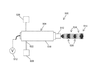
[O0341
Figure 5 is a diagram of an example of an AP plasma application system 500
according to implementations disclosed herein. The system 500 generally
includes an AP
plasma source 504 (or device, applicator, apparatus, instrument, pen, gun,
etc.), a plasma-
generating gas supply source 508, and a power source 512. The AP plasma source
504
generally includes a main body 518 (or support structure, housing, etc.) which
may be
configured for manual use (i.e., handheld) or automated use (e.g., attached to
a multi--axis
robotics system, not shown). For manual operation, a portion of the main body
518 may be
utilized as a handle. The AP plasma source 504 further includes a plasma
outlet at its distal
end from which a plume or jet 514 of AP plasma is generated according to
various
implementations disclosed herein. In the implementation illustrated in Figure
5, the plasma
outlet is the exit of a nozzle 510. The plasma-generating gas supply source
508 is in fluid
communication with a gas inlet 522 of the AP plasma source 504 by any suitable
conduit and
fittings for supplying a suitable plasma-generating gas to the AP plasma
source 504. In one
example, the plasma-generating gas is air, in which case the plasma-generating
gas supply
solace 508 may be a source of low-pressure compressed air. The power source
512 is in
electrical communication with the AP plasma source 504 by any suitable wiring
and
connectors for supplying electrical power according to operating parameters
suitable for
generating and maintaining the type of AP plasma described herein. To Figure
5, the power
source 512 represents the electronics and user controls needed for this
purpose. As
appreciated by persons skilled in the art, the user controls may be configured
as necessary to
enable the setting and adjustment of various operating parameters of the
voltage or current
signal fed to the AP plasma source such as, for example, power level, drive
voltage
amplitude, drive frequency, waveform shape, etc. Electrical signals of AC
(e.g., RV), DC,
pulsed DC, or arbitrary periodic waveforms with or without an applied DC
offset may be
utilized to drive the AP plasma as appropriate for a particular application.
For simplicity,
internal components of the main body 518 of the AP plasma source 504 utilized
for receiving
the electrical and gas inputs and generating the AP plasma therefrom (e.g.,
electrodes, gas
conduits, etc.) are omitted in Figure 5 but readily understood by persons
skilled in the art. In
the case of an air plasma, the plasma-generating gas supply source 508 may
also serve as the
source of active species of the AP plasma (e.g., oxygen- and nitrogen-based
species).
Alternatively, one or more reactive gas supply sources 526 may also be placed
in
communication with the AP plasma source 504 for such purposes as enhancing the
supply of
02 or N2 or for supplying other types of reactive species (e.g., He, Ar, other
noble gases,
7
Date Regue/Date Received 2023-05-01
halogens, N141, CO?, various hydrocarbons, etc.) to specifically tailor the
chemical species for
a given coating type. Alternatively, specific mixtures of either noble or non-
noble gases may
be combined in order to enhance the ionization of secondary, tertiary, or
quaternary, species
or reactions by a process such as Penning ionization..
t00351 The plasma generated by the AP plasma source 504 may be a cold, or
non-
thermal, plasma containing one or more reactive species suitable for
chemically interacting
with a coating in a manner sufficient for causing the coating to be removed
from its
underlying substrate. Generally, the reactive species may include photons,
metastable
species, atomic species, free radicals, molecular fi-agments, monomers,
electrons, and ions.
The reactive species desired to be produced will generally depend on the type
of coating to be
removed. In the case of various polymeric coatings and paints, a highly
oxidizing plasma has
been found to be effective, in which case the predominant reactive species may
include 0,
02: (the asterisk designating the metastable form of diatomic oxygen), and/or
03. In various
implementations, air supplied by the plasma-generating gas supply source 508
may be
sufficient for generating an effective amount of oxygen-based energetic
species for removing
various types of polymeric coatings or paints. Additional non-limiting
examples of active
species that may be formed in the plasma and utilized for material removal
include fluorine,
chlorine, bromine, iodine, nitrogen, or sulphur. One or more of these species
may be utilized,
for example, to selectively etch (or enhance the etching selectivity of) a
primer layer or
adhesion layer if a specialized chemistry or primer formulation has been
employed in the
coated structure. For example, in the case of a primer that exhibits
preferential etching by
oxygen, oxygen species could be used so that the primer layer is
preferentially etched relative
to a topeoating layer. The oxidizer may also be mixed with an inert gas or
relatively inert gas
such as nitrogen or natural air mixtures. It is also possible to use reducing
plasma species
such as hydrogen or ammonia. It is also possible to use neutral or inert gases
to energetically
bombard the interface layer and promote decohesion at the bond line. The type
of oxidizing
species in the plasma plume may be adjusted for specific coating chemistries
to maximize the
etch rate of the coating. For instance, certain coating chemistries may he
quite resistant to an
oxygen-containing oxidizer but could be quite easily etched by a fluorinated
oxidizer.
[0036] As further illustrated in Figure 5, the plasma plume 514 generated
by the AP
plasma source 504 may be configured as a periodic or alternating series of
high plasma
density regions 530 and low plasma density regions 534. The high plasma
density regions
530 may be considered as including shock fronts (or other types of pressure
waves) that
8
Date Regue/Date Received 2023-05-01
propagate in the general direction of the plasma plume 514, i.e., toward a
target coating to he
removed. Tinder appropriate operating conditions, the shock fronts may be
visually
manifested as shock diamonds or Mach disks.
[0037j
Certain pressure regimes, geometrical configurations, and other operational
parameters will give rise to suitable plasma and shock wave generation and
control. In one
implementation, the nozzle 510 is configured to cause rapid expansion of the
gas emanating
therefrom. As an example, the nozzle 510 may have a converging or converging-
diverging
configuration of appropriate dimensions. In this case, the AP plasma generated
within the AP
plasma source 504 flows from the nozzle exit at supersonic velocity and at a
pressure
different from (less than or greater than) the ambient pressure outside the
nozzle exit.
Another example of a nozzle that may he suitable is a non-axially symmetric
nozzle such as
an aerospikc nozzle. In another implementation, the drive .frequency and/or
power level
applied by the power source 512 to the electrical field generating the plasma
are controlled so
as to modulate the pressure waves (e.g., compression waves) generated in the
AP plasma
source 504. Pressure waves generated in such manner may be, or be similar to,
acoustic
shock waves or pressure waves. Similarly, this may be accomplished inductively
by
generating a time-varying magnetic field to modulate the plasma. In another
implementation,
the geometry of the AP plasma source 504 (e.g., the volume and the length-to-
width ratios of
the nozzle 510 and/or upstream plasma-generating chamber) may be selected or
adjusted so
as to selectively filter or enhance certain frequency modes in the pressure
waves of the
plasma. This may be analogous to causing acoustic gain or resonance to occur
to further
enhance the coherency of the shock waves. In another implementation, a
piezoelectric
material, such as for example various known ceramics or polymers (e.g., barium
titanate, lead
zirconium titanate, polyvinylidene fluoride, etc.) may be driven by the power
source 512 to
produce vibrations or oscillations transferred to the as-generated plasma
plume. In another
implementation, the supply gas pressure to the plasma plume may be modulated
in order to
create the necessary pressure waves or shockwaves by rapidly actuating a high
speed gas
valve. For
example, a pneumatically actuated valve, electrically actuated valve or
piezoelectric valve actuator may be used to modulate the pressure being fed
into the AP
plasma device.
[00381
Generally, operating parameters associated with the AP plasma source 504 are
selected so as to produce a stable plasma discharge, with the pressure/shock
waves as desired.
The operating parameters will depend on the particular application, which may
range, for
9
Date Regue/Date Received 2023-05-01
example, from nanoscale etching of micro-fabricated structures or devices
(e.g., 'MEN'S
devices) to removing large areas of paint from aircraft carriers. Examples of
operating
parameters will now be provided with the understanding that the broad
teachings herein are
not limited by such examples. In the case of generating an air plasma, the
rate at which the
air is fed to the AP plasma source 504 may range from 1.xle SCCM to 1)(106
SCCM. The
feed pressure into the AP plasma source 504 may range from I Pa to ix 1 07 Pa.
The power
level of the electrical field driving the plasma may range from -1x1 OW to
lx106W. The
drive frequency of the electrical field may range from DC (0 GI-1z) to 100
GHz. The
separation distance, i.e. the distance from the nozzle exit to the exposed
surface of the
material to be removed, may range from lx10-6 in to 1 in. The scan speed, i.e.
the speed at
which the AP plasma source 504 is rastered across (over) die surface of the
material, may
range from ix10-4 m/s to 10 m/s. Related to the scan speed and power is the
time averaged
power density. Also related to the scan speed is the dwell time, i.e., the
period of time during
which a particular area of the material is exposed to the plasma plume, which
may range from
1x10⁹ s to 43xl.W s (1 month). It will be noted that scan speed (or dwell
time) effectively
characterizes two different techniques for exposing the material to the plasma
plume 514, the
first being moving the AP plasma source 504 relative to the material (i.e.,
the material
remains in a fixed position) and the second being holding the AP plasma source
504
stationary while moving the coated structure relative to the AP plasma source
504. The
foregoing parameters may depend on the composition and thickness of the
material to be
remo veil.
[00391
Figure 6 illustrates an example of utilizing the AP plasma source 594
illustrated in
Figure 5. Specifically, Figure 6 shows the nozzle 519 applying the shock wave-
inclusive
plasma plume 514 to the same or similar coated structure 118 described above
in conjunction
with Figures 1-4. Reactive components of the coating material 124 are removed
by the active
species of the AP plasma. For example, organic compounds may be converted to
CO2 andior
water vapor. In addition, the shock waves 530 (or pressure waves) generated in
the AP
plasma propagate toward the coated structure 118 and impinge on the uppermost
surface 126
of the coating 124. The shock waves 530 disrupt inorganic particles or any
other particles
which a plasma unassisted by shock waves would fail to remove by sole reliance
on active
plasma species or incident gas flow pressure. The loosened particles may then
be swept away
in the gas (e.g., air) stream emanating from the AP plasma source 504 (as part
of the plume
514) and may be disposed of by any suitable means (e.g., a vacuum device). Due
to the
Date Regue/Date Received 2023-05-01
bimodal activity of the shock-assisted plasma plume 514--i.c., a combination
of reactive
species and shock waves 530 in the plasma¨the AP plasma source 504 may be
operated on a
continuous basis to rapidly penetrate the coated structure 118 of any
thickness down to the
substrate 122. Unlike conventional plasmas, the plasma plume 51.4 disclosed
herein is not
impaired by any accumulation of non-reactive or unresponsive components of the
coating
124 and thus its optimized material removal rate may be preserved throughout
the removal
operation.
[0040] The technique taught herein is further illustrated in Figures 7 and
8. Figure 7 is a
cross-sectional elevation view of the coated structure 118 while being
subjected to the shock-
assisted plasma plume 514 at a given instance of time, and Figure 8 is a
similar view of the
coated structure 1.18 at a later instance of time. The coated structure 1.18
in this example is
the same or similar to that illustrated in Figures 2-4. Figure 8 illustrates
the physical
disruption of particles 234 as a result of the intense physical impingement of
shock. waves
530 on the surface 126 of the coating 124. The pressure gradients associated
with these
shock waves 530 may thus be quite significant. The physical disruption helps
to expose new
organic layers of the coating 124, which are now free to be subsequently
removed by the
energetic species of the AP plasma. As shown in Figure 8, eventually all of
the binder 232
(Figure 7) is ablated and successive shock waves 530 release all inorganic
particles 234 down
the surface of the substrate 1,22.
10041.1 The substrate 122 underlying the material 124 to be removed may
have any
composition, e.g., metallic, polymeric, ceramic, composite, etc. Moreover,
generally no
limitation is placed on the type or composition of the material 1.24 to be
removed. As noted
above, the material 124 will generally be one in which at least some of the
components are
responsive to active species of the AP plasma while other components may not
be responsive
and thus are removed primarily or exclusively by the pressure waves 530
generated in the AP
plasma as taught herein. Such materials 124 include, for example, various
types of polymeric
coatings and paints. Generally, no limitation is placed on the thickness of
either the substrate
122 or the material 124 to be removed from the substrate 122. Moreover, the
substrate 122
and associated material 124 to be removed are not required to have a simple
planar or
curvilinear geometry. Instead, the AP plasma source 504 is effective for
treating three-
dimensional topographies, irregular profiles, and complex geometries. The AP
plasma source
504 may be utilized to apply the plasma plume 514 around structural features
such as, for
example, rivets, or inside narrow channels, or in corners Or cracks, etc.
11
Date Regue/Date Received 2023-05-01
[00421 It will also be understood that a "material," "coating," "layer,"
"film" or the like
as used herein encompasses multi-layered, single-layer, or composite
materials. For instance,
a given polymeric material may include a protective overcoat, an adhesion-
promoting layer,
or the like. A paint may include a primer layer, a topcoat, etc. The AP plasma
source 504 is
effective for all such layers or strata of a multi-layered material down to
the underlying
substrate. The AP plasma source 504 may also be utilized to precisely remove
one or more
selected layers of a multi-layered material, leaving underling layers intact
on the substrate.
[0043] Figure 9 is a lengthwise cross-sectional view of an example of an
Al plasma
source 904 that may he configured for producing shock waves in the plasma
plume. The AP
plasma source 904 includes an axially elongated plasma-generating chamber 942
or other
structure that servos as a ground electrode for generating plasma and as a
conduit for flowing
gases and plasma. The plasma-generating chamber 942 may be enclosed in an
electrically-
and thermally-insulating housing (not shown). A "hot" or powered electrode 946
is located
in the plasma-generating chamber 942. Electrical connections to the hot
electrode 946 may
be made through a dielectric structure 950 located at the proximal end of or
in the plasma-
generating chamber 942. One or more gas inlets 958 may be formed through the
dielectric
structure 950 in fluid communication with the plasma-generating chamber 942.
The gas
inlets 958 may be placed in fluid communication with the gas supply source 508
(Figure 5).
Accordingly, the gas inlets 958 provide a now path for plasma-generating gas
fed to a region
962 within the plasma-generating chamber 942 proximate to the hot electrode
946. In
operation, the plasma is generated in this region 962 and subsequently flows
with the gas
flow toward a nozzle 910 positioned at a distal end of the plasma-generating
chamber 942.
[00441 According to another implementation, a piezoelectric material such
as a suitable
ceramic or polymer is positioned in the AP plasma source so as to enable the
electrical output
from the power supply to induce the piezoelectric effect. For example, the
stru.eturc 950
shown in Figure 9 may serve as the piezoelectric element. In this case, the
electrical field
impressed between the hot electrode 946 and the plasma-generating chamber 942
drives the
structure to vibrate. The vibrations are transferred to the plasma and yield
pressure waves in
the plasma plume, which are utilized to impact a coated structure as described
above. The
piezoelectric material may be selected so as to match up with the drive
frequency as closely
as possible for optimizing the piezoelectric effect. Ideally, the drive
frequency utilized
creates a resonance condition (or other condition that promotes the
piezoelectric effect) in the
structure 950, although it will be appreciated that various off-resonant
frequencies may be
12
Date Regue/Date Received 2023-05-01
sufficient for producing pressure waves effective for the coating removal
applications
contemplated herein.
[00451 Figure 10 is a cross-sectional view of another example of an AP
plasma source
1004, in a transverse plane perpendicular to the flow of gases through an
axially elongated
plasma-generating chamber 1042. In this example, gas inlets 1058 are oriented
at an acute
angle (e.g., 45 degrees) relative to the central, longitudinal axis of the
plasma-generating
chamber 1042. By this configuration, gas is introduced into the AP plasma
source 1004 with
a significant tangential vector and consequently flows in the axial direction
in a vortex flow
pattern or path. The tangential gas inlets 1058 may be utilized in any of the
implementations
disclosed herein.
100461 Figure 11 is a cross-sectional view of an example of a nozzle 1110
that may be
utilized in any of the implementations disclosed herein. In this example, the
nozzle 1110 has
a converging-diverging design. Specifically, the nozzle 1110 includes a first,
converging
section 1166 having an inside diameter that tapers down to a second, reduced-
diameter
section or throat 1170, The throat 1170 transitions to a third, diverging
section 1174 having
an inside diameter that increases to a larger-diameter nozzle exit 1178. The
nozzle 1110 may
be dimensioned appropriately as a means for producing pressure waves or shock
waves as
described above. Alternatively, the nozzle 1110 has only a converging design,
i.e., lacks the
diverging section 1174. Converging nozzles as well as converging-diverging
nozzles have
been found by the inventors to be effective for producing pressure waves under
appropriate
operating conditions.
[0047j In another implementation, an AP plasma source having a
configuration similar to
that. shown in Figures 5 and 9, with a converging nozzle (i.e., a straight
conical cross-
sectional flow area without being followed by a diverging section), has been
fabricated and
evaluated. The AP plasma source repeatably and reliably produces a plasma
plume
characterized by shock waves, as evidenced by a clearly visible pattern of
shock diamonds in
the plasma plume, and achieved superior etch rates on coated samples as
compared to
conventional AP plasma sources unassisted by shock waves. The AP plasma source
generated an air plasma using air at about room temperature as the feed gas.
The air may be
fed to an AP plasma source of this type at a pressure ranging from 30-110 psi
and at a flow
rate ranging from 1-7.5 Mk In another example, the pressure range is 65-95
psi. In
another example, the -flow rate range is 1-4 CF].. Pressures higher than 110
psi may also be
13
Date Regue/Date Received 2023-05-01
implemented to produce shock waves. In a more general example, the pressure
may be 30 psi
or greater and the flow rate may be 1 CFM or greater.
[0048] Figure 12 is a set of shadowgrams (Schlieren images) of output
flows from an AP
plasma source at various air pressures and flow rates. in order, starting from
the upper left
image and ending with the lower right image, the conditions were: 98 psi and
7.5 CFM; 90
psi and 7.4 CFM; 80 psi and 6.5 CFM; 70 psi and 5.7 CFM; 60 psi and 5.0 CFM;
50 psi and
4.3 CFM; 40 psi and 3.5 CFM; 30 psi and 2.8 CFM; 20 psi and 2.2 CFM; and 0 psi
and 0
CFM. In these examples, it can be seen that the shock waves are more visible
or pronounced
at the higher pressures and flow rates as compared to the lower pressures and
flow rates.
100401 Figure 13 is a side elevation view of another example of an AP
plasma source
1304 according to another implementation. Figure 14 is a front perspective
view of the front
portion of the AP plasma source 1304 illustrated in Figure 13. The AP plasma
source 1304
includes one or more plasma-generating units 1346 in a main body 1318
communicating with
one or more nozzles (or a manifold) 1310. The nozzle(s) or manifold 1310 are
set back in the
main body 1318 and communicate with a slot-shaped plasma outlet 1322 that
opens at a
distal end 1326 of the main body 1318. By this configuration, the AP plasma
source 1304
produces a wide, predominantly linear or horizontally-oriented plasma plume or
"plasma
line" 1314 with wide, predominantly linear or horizontally-oriented shock
waves or pressure
waves 1330.
100501 While the foregoing description of implementations of the AP
plasma source has
focused primarily on material removal techniques, it will be understood that
various
implementations of the AP plasma source may be utilized tor other operations
such as, for
example, surface treatment or functionalization.
0051j Another potential application fOr the AP plasma source is in
dentistry. With the
correct etching chemistry of the plasma plume, the shock waves may be utilized
to perform
micro-etching of the hydroxyapetite within cavities or the surface of the
teeth. A secondary
effect would be the sterilization of the cavity or hole. This could possibly
replace employing
hard drills.
100521 in general, terms such as "communicate" and "in .
communication with" (for
example, a first component "communicates with" or "is in communication with" a
second
component) are used herein to indicate a structural, functional, mechanical,
electrical, signal,
optical, magnetic, electromagnetic, ionic or fluidic relationship between two
or more
components or elements. As such, the fact that one component is said to
communicate with a
14
Date Regue/Date Received 2023-05-01
second component is not intended to exclude the possibility that additional
components may
be present between, and/or operatively associated or engaged with, the first
and second
components.
[00531 it
will be understood that various aspects or details of the invention may be
changed without departing from the scope of the invention. Furthermore, the
foregoing
description is for the purpose of illustration only, and not for the purpose
of limitation the
invention being defined by the claims.
Date Regue/Date Received 2023-05-01