Note: Descriptions are shown in the official language in which they were submitted.
WO 2022/154971
PCT/US2021/065718
- 1 -
DOWNHOLE PLUG DEPLOYMENT
TECHNICAL FIELD
This disclosure relates generally to equipment utilized and operations
performed in conjunction with a subterranean well and, in one example
described
below, more particularly provides for plug deployment downhole.
BACKGROUND
It can be advantageous to be able to control fluid flow in a well. For
example, well tools can be activated or deactivated by deploying a plug into a
tubular string from the surface. Plugs can be used to operate valves or
prevent
flow through flow passages when desired.
Therefore, it will be appreciated that improvements are continually needed
in the art of controlling fluid flow in a well. The present disclosure
provides such
improvements, which may be utilized in a wide variety of different well
operations
and with a wide variety of different well systems.
BRIEF DESCRIPTION OF THE DRAWINGS
FIG. 1 is a representative partially cross-sectional view of an example of a
well system and associated method which can embody principles of this
disclosure.
FIGS. 2A & B are representative partially cross-sectional views of
examples of vibratory tools that may be used with the FIG. 1 system and
method.
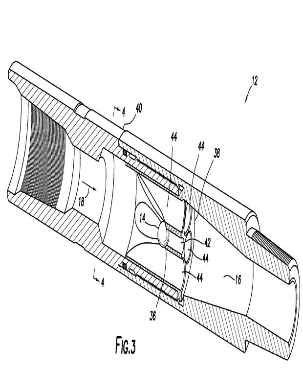
FIG. 3 is a representative cross-sectional and perspective view of an
example of a plug release tool that can embody the principles of this
disclosure.
CA 03199582 2023- 5- 18
WO 2022/154971
PCT/US2021/065718
- 2 -
FIG. 4 is a representative cross-sectional view of the plug release tool,
taken along line 4-4 of FIG. 3.
FIG. 5 is a representative cross-sectional view of the plug release tool,
taken along line 5-5 of FIG. 4.
FIG. 6 is a representative cross-sectional and perspective view of the plug
release tool with an example of a plug.
FIG. 7 is a representative cut-away view of the plug.
FIG. 8 is a representative cross-sectional and perspective view of the plug
release tool with another example of the plug.
FIG. 9 is a representative cut-away view of the FIG. 8 plug.
FIG. 10 is a representative cross-sectional and perspective view of
another example of the plug release tool with another example of the plug.
FIG. 11 is a representative cross-sectional and perspective view of a
portion of the FIG. 10 plug release tool.
FIG. 12 is a representative cross-sectional view of an example of an insert
section of the FIG. 10 plug release tool.
FIG. 13 is a representative end view of the insert section.
FIG. 14 is a representative cross-sectional view of the insert section with
another example of the plug.
DETAILED DESCRIPTION
Representatively illustrated in FIG. 1 is a system 10 for use with a
subterranean well and an associated method which can embody principles of this
disclosure. However, it should be clearly understood that the system 10 and
method are merely one example of an application of the principles of this
disclosure in practice, and a wide variety of other examples are possible.
Therefore, the scope of this disclosure is not limited at all to the details
of the
system 10 and method described herein and/or depicted in the drawings.
CA 03199582 2023- 5- 18
WO 2022/154971
PCT/US2021/065718
- 3 -
In the FIG. 1 example, a drill string 62 has been deployed into a wellbore
60, in order to drill the wellbore further into the earth. For this purpose,
the drill
string 62 includes a drill bit 64 connected at its distal end. The drill bit
64 is part of
a tool string 68 or bottom hole assembly (BHA). Note that it is not necessary
in
keeping with the principles of this disclosure for a BHA to be positioned at a
bottom of a hole, wellbore or any other specific position in a well.
In addition, it is not necessary for a drilling operation to be performed. The
drill string 62 could be another type of tubular string, such as a completion
string,
a workover string, etc. The scope of this disclosure is not limited to any
particular
well operation or function performed with a tubular string in a well.
As depicted in FIG. 1, a vibratory tool 22 is connected in the drill string 62
as part of the BHA 68. The vibratory tool 22 is used in this example to assist
in
deploying the drill string 62 into a generally horizontal section of the
wellbore 60.
When operational, the vibratory tool 22 produces vibrations, for example, due
to
pressure fluctuations, accelerations of mass, impacts, or other stimulus
caused
by the vibratory tool. The vibrations produced by the vibratory tool 22 reduce
friction between the drill string 62 and the wellbore 60, thereby enabling the
drill
string to displace more readily along the wellbore.
A downhole plug release tool 12 is also connected in the drill string 62 as
part of the BHA 68. The plug release tool 12 is used to release a plug (such
as, a
ball, a dart, etc.) downhole, so that the plug can engage the vibratory tool
22 to
thereby operate the vibratory tool. In this example, the engagement of the
plug
with the vibratory tool 22 may be used to activate or deactivate the vibratory
tool,
that is, to cause the vibrations to be produced by the vibratory tool, or to
cause
the vibrations to cease.
In other examples, the vibratory tool 22 may not be used. For example, the
release of the plug 14 could instead be used to operate a drill motor 66, a
stabilizer, a reamer, or another type of well tool. The scope of this
disclosure is
not limited to use of the plug release tool 12 to operate any particular type
of well
tool, or to cause any particular function to be performed in the well. The
plug
release tool 12 may be used to activate or deactivate any type of well tool.
CA 03199582 2023- 5- 18
WO 2022/154971
PCT/US2021/065718
- 4 -
As depicted in FIG. 1, the vibratory tool 22 is positioned in a generally
horizontal section of the wellbore 60. It is desired in this example for the
vibratory
tool 22 to produce vibrations when the BHA 68 is in the generally horizontal
section of the wellbore 60, since this is when the friction between the drill
string
62 and the wellbore is greatest, and vibrations may be undesirable when the
BHA
68 is in a generally vertical section of the wellbore.
Note that it is not necessary for the BHA 68 or any other portion of a
tubular string to be positioned in a generally horizontal or otherwise
inclined
section of a wellbore, or for the wellbore to even include a generally
horizontal
section, when a well tool is operated using the plug release tool 12. The plug
release tool 12 could be used to operate a well tool in a vertical section of
a
wellbore in keeping with the scope of this disclosure.
In some examples it may be desired to cease operation of the vibratory
tool 22 when the drill motor 66 and drill bit 64 are being used to drill into
the
earth. For example, the vibrations produced by the vibratory tool 22 might
otherwise be too energetic when sufficient fluid is flowed through the drill
string
62 to operate the drill motor 66. In such examples, it may be desired to cease
production of the vibrations after the BHA 68 is positioned in the generally
horizontal section of the wellbore 60 but before commencing drilling.
Referring now to FIGS. 2A & B, two examples of how the plug release tool
12 may be used to operate the vibratory tool 22 are representatively
illustrated.
However, as mentioned above, it should be clearly understood that the scope of
this disclosure is not limited to operating a vibratory tool using the plug
release
tool 12, or to operating the vibratory tool 22 in any particular manner.
In the FIG. 2A example, the plug release tool 12 is used to release a plug
14 into a fluid passage 16 of the plug release tool. Fluid flow 18 through the
passage 16 conveys the plug 14 into a fluid passage 20 of the vibratory tool
22.
The plug 14 may be released in the plug release tool 12 in response to any
type
of stimulus including, for example, passage of a predetermined time period,
exposure to well fluid, degrading (e.g., dissolution, corrosion, melting,
oxidation,
hydration, etc.) of a layer of the plug, a change in orientation of the plug
release
CA 03199582 2023- 5- 18
WO 2022/154971
PCT/US2021/065718
- 5 -
tool, and/or a variation in the fluid flow 18 through the plug release tool,
or a
combination of any of these. The scope of this disclosure is not limited to
any
particular stimulus or cause for release of the plug 14.
The fluid passage 20 splits in the vibratory tool 22 into an operational flow
passage 24 and a bypass flow passage 26. Sufficient fluid flow through the
operational flow passage 24 will cause a predetermined pressure differential
across a vibratory device 28 and thereby cause the vibratory device to produce
vibrations.
The vibratory tool 22 and vibratory device 28 in the FIG. 2A example may
be similar to those described in US patent no. 9957765, which is incorporated
herein by this reference in its entirety for all purposes. Other types of
vibratory
tools and vibratory devices may be used in keeping with the scope of this
disclosure.
When the bypass flow passage 26 is open, the predetermined pressure
differential is not produced across the vibratory device 28, because the fluid
flow
18 is permitted to pass through the bypass flow passage instead of, or in
addition
to, the operational flow passage 24. However, when the plug 14 sealingly
engages a seat 30 in the bypass flow passage 26 (a screen, filter or other
exclusion device 32 prevents the plug from being conveyed into the operational
flow passage 24), the bypass flow passage is closed and the fluid flow 18
through
the bypass flow passage is prevented.
The predetermined pressure differential across the vibratory device 28 is,
thus, achieved and the vibrations are produced. In this manner, the vibratory
tool
22 can be operated to begin producing the vibrations downhole when desired
(such as, when the BHA 68 is in the generally horizontal section of the
wellbore
60 in the FIG. 1 system 10).
In the FIG. 2B example, the vibratory device 28 is initially able to produce
vibrations downhole in response to the fluid flow 18. The bypass flow passage
26
is closed and the predetermined pressure differential can be produced across
the
vibratory device 28. The vibratory tool 22 can be operated to cease production
of
the vibrations when desired.
CA 03199582 2023- 5- 18
WO 2022/154971
PCT/US2021/065718
- 6 -
The fluid flow 18 through the bypass flow passage 26 is initially prevented
by a sliding sleeve 34. The sliding sleeve 34 may be retained in this initial
position by releasable means, such as, a shear pin, snap ring, collets, etc.
(not
shown).
When the plug 14 is released by the plug release tool 12, the plug can be
conveyed by the fluid flow 18 into sealing engagement with the seat 30, which
is
formed in the sliding sleeve 34 in this example. This sealing engagement
prevents the fluid flow 18 from passing through the operational flow passage
24
and, thus, causes the vibrations to cease being produced by the vibratory
device
28. In addition, the sleeve 34 will displace to a position in which the fluid
flow 18
is permitted to pass through the bypass flow passage 26.
The vibratory tool 22 and vibratory device 28 in the FIG. 2B example may
be similar to those described in US patent no. 9181767, which is incorporated
herein by this reference in its entirety for all purposes. Other types of
vibratory
tools and vibratory devices may be used in keeping with the scope of this
disclosure.
In FIGS. 3-5, an example of the downhole plug release tool 12 is
representatively illustrated. In this example, the plug 14 is released from
the plug
release tool 12 in response to a combination of a change in orientation of the
plug
release tool and a change in the fluid flow 18 through the plug release tool.
As depicted in FIG. 3, the plug release tool 12 is in an inclined or generally
horizontal orientation. The plug 14 is engaged with a seat 36 formed in an
insert
38 secured in an outer housing 40. Multiple flow passages 42, 44 extend
longitudinally through the insert 38 and form portions of the flow passage 16,
which extends longitudinally through the outer housing 40.
The flow passage 42 is centrally located in the insert 38. The fluid flow 18
causes a pressure differential to be created across the plug 14 when it is
engaged with the seat 36. In this manner, the plug 14 is maintained in
engagement with the seat 36, even though the plug release tool 12 is in an
inclined or horizontal orientation.
CA 03199582 2023- 5- 18
WO 2022/154971
PCT/US2021/065718
- 7 -
When the plug release tool 12 is initially deployed into the wellbore 60 as
part of the BHA 68 in the FIG. 1 system 10, the plug release tool is in a
generally
vertical orientation, and the plug 14 is engaged with the seat 36, thereby
closing
off the flow passage 42. Thereafter, the fluid flow 18 through the drill
string 62 will
maintain the plug 14 engaged with the seat 36 (due to a pressure differential
created across the plug by the fluid flow), even after the orientation of the
tool 12
changes to inclined or horizontal.
When it is desired to release the plug 14, for example, to operate the
vibratory tool 22, the fluid flow 18 is ceased, so that the pressure
differential
across the plug is relieved. If, at this point, the plug release tool 12 is in
a
horizontal or sufficiently inclined orientation, the plug 14 will fall away
from the
seat 36 by action of gravity. The plug release tool 12 may be positioned in a
horizontal or sufficiently inclined orientation before or after the fluid flow
18 is
ceased.
In FIG. 4, a cross-sectional view of the plug release tool 12 is
representatively illustrated. In this view, the plug 14 is not depicted, and
it can be
seen that there are six of the flow passages 44 circumferentially distributed
about
the central flow passage 42. One of the flow passages 44 is in a lowermost
position, directly below the central flow passage 42. However, it is not
necessary
for the lowermost flow passage 44 to be positioned directly below the central
flow
passage 42.
The number of flow passages 44 can be varied as desired. Preferably,
there are enough of the flow passages 44 to ensure that at least one of them
will
be appropriately positioned, when the plug release tool 12 is in a
sufficiently
inclined or horizontal orientation, so that the plug 14 can be conveyed
through the
lowermost flow passage by the fluid flow 18.
In FIG. 5, the plug release tool 12 is representatively illustrated after the
plug 14 has fallen away from the seat 36. The plug 14 can now be conveyed by
the fluid flow 18 through the lowermost flow passage 44.
Note that, in this example, the plug 14 is too large in diameter to pass
through the flow passage 42, but the plug is not too large to pass through the
flow
CA 03199582 2023- 5- 18
WO 2022/154971
PCT/US2021/065718
- 8 -
passages 44. In the event that the plug 14 should fail to fall away from the
seat
36 after the fluid flow 18 is ceased and the plug release tool 12 is in a
sufficiently
inclined or horizontal orientation, another plug could be deployed into the
flow
passage 16 (such as, deployed from surface), and this other plug could be
conveyed through the lowermost (or other) flow passage 44 by the fluid flow 18
and into the vibratory tool 22 (or other well tool) to operate the well tool.
In FIGS. 6 & 7 another example of the plug release tool 12 is
representatively illustrated. In this example, the plug 14 has at least one
outer
layer that initially prevents it from passing through the flow passages 44. In
this
manner, the plug 14 cannot inadvertently fall away from the seat 36 and pass
through one of the flow passages 44 before it is intended to operate the
vibratory
tool 22 (or other well tool).
As depicted in FIG. 6 it may be seen that, with the outer layer on the plug
14, the plug is too large to pass through any of the flow passages 44.
However, if
the outer layer is degraded or dispersed downhole, so that an outer diameter
of
the plug 14 is decreased in this example, the plug will be able to pass
through
one of the flow passages 44.
As depicted in FIG. 7, the outer layer 46 covers an inner core 48 of the
plug 14. The inner core 48 may be made of a suitably strong and tough material
(such as, steel, tungsten carbide, etc.). However, the scope of this
disclosure is
not limited to use of any particular material for the inner core 48.
The outer layer 46 may be made of any material that will degrade or
disperse downhole as desired. For example, the outer layer material may
degrade in response to exposure to well fluid (either naturally occurring or
later
introduced), or in response to passage of a predetermined period of time. The
outer layer material may dissolve, corrode, oxidize or hydrate in well fluid.
The
outer layer material may melt when exposed to downhole temperature. The outer
layer material may comprise a eutectic material, magnesium, a dissolvable
plastic, ploy-glycolic acid, poly-lactic acid, anhydrous boron, paraffin or
wax, etc.
The scope of this disclosure is not limited to any particular material of the
outer
layer 46.
CA 03199582 2023- 5- 18
WO 2022/154971
PCT/US2021/065718
- 9 -
The plug release tool 12 of FIGS. 6 & 7 operates in a similar manner to the
plug release tool of FIGS. 3-5, except that the plug 14 cannot pass through
the
flow passages 44 until the outer layer 46 is degraded or dispersed. Note that,
in
this example, the plug 14 is initially too large in diameter to pass through
the flow
passages 42, 44, but when the outer layer 46 is degraded or dispersed the plug
is not too large to pass through the flow passages 44. In the event that the
plug
14 should fail to fall away from the seat 36 after the fluid flow 18 is ceased
and
the plug release tool 12 is in a sufficiently inclined or horizontal
orientation,
another plug could be deployed into the flow passage 16 (such as, deployed
from
surface), and this other plug could be conveyed through the lowermost (or
other)
flow passage 44 by the fluid flow 18 and into the vibratory tool 22 (or other
well
tool) to operate the well tool.
In FIGS. 8 & 9 another example of the plug release tool 12 is
representatively illustrated. In this example, the plug 14 has multiple outer
layers
that initially prevent it from passing through the flow passages 44. In this
manner,
the plug 14 cannot inadvertently fall away from the seat 36 and pass through
one
of the flow passages 44 before it is intended to operate the vibratory tool 22
(or
other well tool).
As depicted in FIG. 8 it may be seen that, with the multiple outer layers on
the plug 14, the plug is too large to pass through any of the flow passages
42, 44.
However, if the outer layers are degraded or dispersed downhole, so that an
outer diameter of the plug 14 is decreased in this example, the plug will be
able
to pass through one of the flow passages 44.
As depicted in FIG. 9, a layer 50 covers an inner core 48 of the plug 14.
The layer 50 may be made of any material that will degrade or disperse
downhole
as desired. For example, any of the materials described above for the outer
layer
46 may be used for the material of the layer 50. The scope of this disclosure
is
not limited to any particular material of the layer 50.
An outer layer 52 covers the layer 50 of the plug 14. The outer layer 52
may be made of any material that will degrade or disperse downhole as desired.
For example, any of the materials described above for the layers 46, 50 may be
CA 03199582 2023- 5- 18
WO 2022/154971
PCT/US2021/065718
- 10 -
used for the material of the layer 52. The scope of this disclosure is not
limited to
any particular material of the layer 52.
In one example, the outer layer 52 could be made of a material that
degrades or disperses in response to exposure to elevated well temperature
(such as, a eutectic, paraffin or wax material). In this manner, the outer
layer 52
would not degrade at or near the surface, but would melt or otherwise degrade
and, thus, permit exposure of the layer 50 to well fluids, when the plug
release
tool 12 is sufficiently deep in the well and the fluid flow 18 is established
to
prevent inadvertent dislodgment of the plug 14 from the seat 36.
In this example, the layer 50 could be made of a material that dissolves,
corrodes, oxidizes, hydrates or otherwise degrades or disperses in response to
contact with well fluid. The layer 50 is prevented from contacting the well
fluid
until the outer layer 52 is degraded or dispersed. After the layer 50 is
degraded or
dispersed, the outer diameter of the plug 14 is small enough to allow the plug
to
pass through one of the flow passages 44 with the fluid flow 18.
The plug release tool 12 of FIGS. 8 & 9 operates in a similar manner to the
plug release tool of FIGS. 3-7, except that the plug 14 cannot pass through
the
flow passages 44 until both of the layers 50, 52 are degraded or dispersed.
Note
that, in this example, the plug 14 is initially too large in diameter to pass
through
the flow passages 42, 44, but when the layers 50, 52 are degraded or dispersed
the plug is not too large to pass through the flow passages 44.
In the event that the plug 14 should fail to fall away from the seat 36 after
the fluid flow 18 is ceased and the plug release tool 12 is in a sufficiently
inclined
or horizontal orientation, another plug could be deployed into the flow
passage 16
(such as, deployed from surface), and this other plug could be conveyed
through
the lowermost (or other) flow passage 44 by the fluid flow 18 and into the
vibratory tool 22 (or other well tool) to operate the well tool.
In FIGS. 10-13, another example of the downhole plug release tool 12 is
representatively illustrated. In this example, the plug 14 is not retained by
the fluid
flow 18 against the seat 36 until it is desired to release the plug. Instead,
the plug
CA 03199582 2023- 5- 18
WO 2022/154971
PCT/US2021/065718
-11 -
14 is retained by a retainer structure 54 that degrades or disperses downhole
in
order to release the plug 14.
The plug 14 and the retainer structure 54 are secured in the insert 38 by
means of a threaded member 56. In other examples, the plug 14 and retainer
structure 54 could be secured in the insert 38 without use of the threaded
member 56, the retainer structure and the threaded member could be integrated
as a single element, etc. The scope of this disclosure is not limited to any
particular details of any of the plug release tool 12 examples as described
herein
or depicted in the drawings.
The retainer structure 54 is made of a material that degrades or disperses
in the well environment as desired. For example, any of the materials
described
above for use in the layers 46, 50, 52 may be used in the retainer structure
54.
Thus, the plug 14 is initially retained in the insert 38 by the retainer
structure 54 until the material of the retainer structure degrades or
disperses in
the well. This allows the plug 14 to fall by action of gravity (when the plug
release
tool 12 is in a sufficiently inclined or horizontal orientation) to a position
in which
the fluid flow 18 can convey the plug through one of the flow passages 44, and
then through the remainder of the flow passage 16 to the vibratory tool 22 (or
other well tool).
As in the FIGS. 3-9 examples, the FIGS. 10-13 example of the plug
release tool 12 needs to be in a sufficiently inclined or horizontal
orientation, in
order for the plug 14 to fall and be released for conveyance with the fluid
flow 18
to the vibratory tool 22 (or other well tool). However, in the FIGS. 10-13
example,
the fluid flow 18 does not need to be ceased in order to allow the plug 14 to
fall.
As in the FIGS. 6-9 examples, the FIGS. 10-13 example of the plug
release tool 12 requires a material to be degraded or dispersed, in order for
the
plug 14 to be released for conveyance with the fluid flow 18 to the vibratory
tool
22 (or other well tool). However, in the FIGS. 10-13 example, a material needs
to
be degraded or dispersed in order for the plug 14 to fall in the insert 38,
but no
material of the plug 14 itself is degraded or dispersed. Instead, a material
retaining the plug 14 is degraded or dispersed. The plug 14 itself is small
enough
CA 03199582 2023- 5- 18
WO 2022/154971
PCT/US2021/065718
- 12 -
to pass through the flow passages 44 any time it is released from the retainer
structure 54.
Note that radially extending passages 58 are formed in the insert 38 to
enable the plug 14 to fall when the retainer structure 54 is degraded or
dispersed.
In the event that the plug 14 should fail to fall from the insert 38 when the
retainer
structure 54 is degraded and the plug release tool 12 is in a sufficiently
inclined or
horizontal orientation, another plug could be deployed into the flow passage
16
(such as, deployed from surface), and this other plug could be conveyed
through
the lowermost (or other) flow passage 44 by the fluid flow 18 and into the
vibratory tool 22 (or other well tool) to operate the well tool.
In FIG. 14, another example of the plug release tool 12 is representatively
illustrated, although only the plug 14, insert 38, retainer structure 54 and
threaded
member 56 are depicted. The remainder of the FIG. 14 plug release tool 12 is
the
same as or similar to the FIGS. 10-13 example.
As depicted in FIG. 14, the retainer structure 54 is elongated as compared
to the FIGS. 10-13 example. The FIG. 14 elongated retainer structure 54
positions the plug 14 so that it is more closely aligned with the radial
passages 58
in the insert 38. In this manner, the plug 14 will more readily fall through
one of
the radial passages 58 when the retainer structure 54 is degraded or
dispersed.
As a result, the plug 14 can fall in the insert 38, so that it can be conveyed
with
the fluid flow 18 to the vibratory tool 22 (or other well tool) at less
inclined (more
vertical) orientations.
It may now be fully appreciated that the above disclosure provides
significant advancements to the art of deploying plugs in a well. In examples
described above, a plug 4 can be deployed from the plug release tool 12 when
desired to activate or deactivate a well tool, such as, the vibratory tool 22.
A downhole plug release tool 12, system 10 and method are provided to
the art. In one example, a plug 14 is released from the plug release tool 12
downhole, and the plug is then engaged with a well tool to thereby operate the
well tool.
CA 03199582 2023- 5- 18
WO 2022/154971
PCT/US2021/065718
- 13 -
The operation of the well tool may comprise activating or deactivating a
vibratory device 22. The operation of the well tool may comprise opening or
closing a bypass passage 26 of the well tool. The operation of the well tool
may
comprise activating or deactivating a drill motor 66, reamer, stabilizer or
other
well tool.
The plug 14 may be released in response to passage of a predetermined
time period, exposure to well fluid, degrading (e.g., dissolution, corrosion,
melting, oxidation, hydration, etc.) of a layer 46, 50, 52 of the plug or a
structure
54 retaining the plug, a change in orientation of the plug release tool 12,
and/or a
variation in fluid flow 18 through the plug release tool.
The plug 14 may comprise one or more outer layers 46, 50, 52. The plug
14 may be released when the one or more outer layers 46, 50, 52 is degraded,
so that the plug is smaller than a passage 44 for fluid flow 18 through the
plug
release tool 12.
The plug 14 may comprise a layer 52 that degrades when exposed to
downhole temperature, and another layer 50 that degrades when exposed to well
fluid. The layer 50 that degrades when exposed to well fluid may be disposed
inside the layer 52 that degrades when exposed to downhole temperature.
The above disclosure also provides a method of deploying a plug 14 in a
subterranean well. In one example, the method can comprise: positioning a tool
string 68 in the well, the tool string 68 including a plug release tool 12 and
a well
tool (e.g., the vibratory tool 22, a stabilizer, etc.); then releasing the
plug 14 from
the plug release tool 12; and then operating the well tool in response to
releasing
the plug 14.
The positioning step can include maintaining a fluid flow 18 through the
plug release tool 12, thereby maintaining the plug 14 engaged with a seat 36
of
the plug release tool 12. The seat 36 may be encircled by multiple flow
passages
44 in the plug release tool 12.
The releasing step can include ceasing the fluid flow 18, thereby permitting
the plug 14 to disengage from the seat 36. The method can include resuming the
CA 03199582 2023- 5- 18
WO 2022/154971
PCT/US2021/065718
- 14 -
fluid flow 18 after the step of ceasing the fluid flow 18, thereby displacing
the plug
14 through one of the flow passages 44 to the well tool.
The step of maintaining the fluid flow 18 may be performed at least
partially while the tool string 68 is in a vertical section of a wellbore 60.
The step
of ceasing the fluid flow 18 may be performed while the tool string 68 is in
an
inclined section of the wellbore 60.
The releasing step can include degrading a layer 46, 50, 52 of the plug 14
in the plug release tool 12. The degrading step can include reducing a
diameter
of the plug 14, thereby permitting the plug 14 to displace through a flow
passage
44 of the plug release tool 12.
The releasing step can include degrading first and second layers 50, 52 of
the plug 14. The first layer 50 may degrade in response to contact with a well
fluid and the second layer 52 may degrade in response to exposure to elevated
temperature in the well.
The positioning step can include a retainer structure 54 of the plug release
tool 12 preventing displacement of the plug 14 through a flow passage 44 of
the
plug release tool 12. The releasing step can include degrading the retainer
structure 54.
The operating step can include activating or deactivating the well tool. The
well tool may comprise a vibratory tool 22, and the operating step may include
the vibratory tool 22 producing vibrations, or preventing the vibratory tool
22 from
producing vibrations.
Also described above is a plug release tool 12 for use in a subterranean
well. In one example, the plug release tool 12 can comprise: an outer housing
40;
and an insert 38 secured in the outer housing 40. The insert 38 can comprise
multiple longitudinally extending flow passages 42, 44 formed through the
insert
38.
The plug release tool 12 may include a plug seat 36 formed in the insert
38. The flow passages 42, 44 may comprise a first flow passage 42 and multiple
second flow passages 44. The plug seat 36 may encircle the first flow passage
CA 03199582 2023- 5- 18
WO 2022/154971
PCT/US2021/065718
-15-
42, and the second flow passages 44 may be circumferentially distributed about
the first flow passage 42.
Each of the second flow passages 44 may have a diameter greater than a
diameter of the first flow passage 42. The plug release tool 12 may include a
plug
14. The first flow passage 42 may have a diameter less than a diameter of the
plug 14, and each of the second flow passages 44 may have a diameter greater
than the plug 14 diameter.
The plug release tool 12 may include a retainer structure 54 and a plug 14.
The retainer structure 54 may releasably secure the plug 14 in the insert 38.
The retainer structure 54 may be degradable downhole. The flow
passages 44 may be circumferentially distributed about the retainer structure
54.
The plug release tool 12 may include a plug 14. The plug 14 may comprise
an inner core 48 and at least one layer 46, 50, 52 surrounding the inner core
48.
The flow passages 42, 44 may comprise a first flow passage 42 and
multiple second flow passages 44. The first flow passage 42 may have a
diameter less than a diameter of the inner core 48, and each of the second
flow
passages 44 may have a diameter greater than a diameter of the inner core 48.
The "at least one" layer 46, 50, 52 may be degradable downhole. The "at
least one" layer 46, 50, 52 may comprise first and second layers 50, 52. The
first
layer 50 may be degradable in response to contact with a well fluid, and the
second layer 52 may be degradable in response to exposure to elevated
downhole temperature.
Although various examples have been described above, with each
example having certain features, it should be understood that it is not
necessary
for a particular feature of one example to be used exclusively with that
example.
Instead, any of the features described above and/or depicted in the drawings
can
be combined with any of the examples, in addition to or in substitution for
any of
the other features of those examples. One example's features are not mutually
exclusive to another example's features. Instead, the scope of this disclosure
encompasses any combination of any of the features.
CA 03199582 2023- 5- 18
WO 2022/154971
PCT/US2021/065718
- 16 -
Although each example described above includes a certain combination of
features, it should be understood that it is not necessary for all features of
an
example to be used. Instead, any of the features described above can be used,
without any other particular feature or features also being used.
It should be understood that the various embodiments described herein
may be utilized in various orientations, such as inclined, inverted,
horizontal,
vertical, etc., and in various configurations, without departing from the
principles
of this disclosure. The embodiments are described merely as examples of useful
applications of the principles of the disclosure, which is not limited to any
specific
details of these embodiments.
In the above description of the representative examples, directional terms
(such as "above," "below," "upper," "lower," "upward," "downward," etc.) are
used
for convenience in referring to the accompanying drawings. However, it should
be
clearly understood that the scope of this disclosure is not limited to any
particular
directions described herein.
The terms "including," "includes," "comprising," "comprises," and similar
terms are used in a non-limiting sense in this specification. For example, if
a
system, method, apparatus, device, etc., is described as "including" a certain
feature or element, the system, method, apparatus, device, etc., can include
that
feature or element, and can also include other features or elements.
Similarly, the
term "comprises" is considered to mean "comprises, but is not limited to."
Of course, a person skilled in the art would, upon a careful consideration
of the above description of representative embodiments of the disclosure,
readily
appreciate that many modifications, additions, substitutions, deletions, and
other
changes may be made to the specific embodiments, and such changes are
contemplated by the principles of this disclosure. For example, structures
disclosed as being separately formed can, in other examples, be integrally
formed and vice versa. Accordingly, the foregoing detailed description is to
be
clearly understood as being given by way of illustration and example only, the
spirit and scope of the invention being limited solely by the appended claims
and
their equivalents.
CA 03199582 2023- 5- 18