Note: Descriptions are shown in the official language in which they were submitted.
CA 03200727 2023-05-03
WO 2022/101727
PCT/IB2021/059917
1
"Plant and process for energy storage and method for controlling a heat
carrier in a plant and/or in a process for energy storage"
DESCRIPTION
Field of the finding
The object of the present invention is a plant and a process for energy
storage.
More precisely, the object of the present invention is a system capable of
absorbing/using mechanical/electrical energy from a grid and/or from a system,
for
lo example in the periods when there is excess availability/or scarce
consumption,
capable of maintaining the stored energy over time and capable of transforming
it
into mechanical/electrical energy and reintroducing it into the network and/or
into
the system at the times of request of said mechanical/electrical energy. In
particular, the present invention refers to a method for controlling a heat
carrier in
a plant and/or in a process for energy storage.
Background of the finding
One such type of system is for example illustrated in the public document WO
2020/039416, on behalf of the same Applicant, which illustrates a process and
plant for energy storage. The plant of WO 2020/039416 comprises a casing for
the
storage of a working fluid different from atmospheric air, in gaseous phase
and in
pressure equilibrium with the atmosphere; a tank for the storage of such
working
fluid in liquid or supercritical phase with a temperature close to the
critical
temperature, wherein the critical temperature is close to the ambient
temperature.
The plant is configured for carrying out a closed cyclic thermodynamic
transformation, first in one direction in a charge configuration and then in
an
opposite direction in a discharge configuration, between the casing and the
tank.
In the charge configuration the plant accumulates heat and pressure and in the
discharge configuration generates energy.
Definitions
CA 03200727 2023-05-03
WO 2022/101727
PCT/IB2021/059917
2
In the present description and in the enclosed claims, reference will be made
to
the following definitions.
= Thermodynamic cycle (TC): thermodynamic transformation from a point X
to a point Y, where X coincides with Y; the TC unlike the CTT (Cyclic
thermodynamic transformation) mentioned below does not have mass
accumulations (significant for energy purposes) within the cycle, while the
CTT typically works between two working fluid storages, one initial and the
other final;
= Cyclic thermodynamic transformation (CTT): thermodynamic transformation
lo
from a point X to a point Y and from a point Y to a point X, without
necessarily passing from the same intermediate points;
= Closed TC and/or CTT: without mass exchange (significant for energy
purposes) with the atmosphere;
= Open TC and/or CTT: with mass exchange (significant for energy purposes)
with the atmosphere.
Summary
For systems of the type described in WO 2020/039416, the Applicant has
observed that, due to the performances of the machines of the plant which
operate
the cyclic thermodynamic transformation (CTT) and the "thermal" performances
of
the cycle, heat to be disposed of in the environment is always present. For
example, by assuming a Round Trip Efficiency (RTE) of 80%, 20% must be
dissipated into the environment.
The need to be able to exchange heat with the environment arises from the
ability
to decide the temperature level (and hence pressure level) of the storage
phase of
the cyclic thermodynamic transformation (CTT), i.e. at which temperature and
hence pressure to accumulate the mass of the working fluid in liquid
conditions.
Relatively low pressures are preferable, for example, for the sizing of the
system,
since they allow limiting the thicknesses of the tanks, of the piping, etc.
and
simplifying the machines, and this translates into a considerable reduction of
the
plant attainment costs.
CA 03200727 2023-05-03
WO 2022/101727
PCT/IB2021/059917
3
The Applicant has observed that part of the heat to be dissipated can be
easily
disposed of since it is generated at average temperatures, for example
mechanical
and electrical losses, which are transferred into the lubrication oil or into
the
cooling air and which are easily disposed of in the environment since their
temperature is typically higher than the ambient temperature.
The Applicant has also observed that part of the above-described heat to be
disposed of is instead close to ambient temperature and is more difficult to
dispose
of. Indeed, in a CTT system, the heat can exit at a specific point of the
process if it
has a temperature greater than the ambient temperature/source temperature,
lo while if it doesn't have a temperature greater than the ambient
temperature/source
temperature it can enter.
In order to allow an exchange of heat with the environment, at the inlet or
outlet,
independent of the ambient temperature, i.e. in order to uncouple the
operation of
the CTT system from the ambient temperature, it is known, through devices that
are external with respect to the cyclic thermodynamic transformation (CTT)
such
as heat pumps or chillers, to create an artificial source at a temperature
higher or
lower than the ambient temperature. Such known solution type is for example
illustrated in WO 2020/039416 which, in figure 9, shows that the secondary
circuit
thereof traversed by the secondary fluid or heat carrier (useful for the
condensation and for the evaporation) is operatively connected to an auxiliary
refrigerator.
The Applicant has however observed that the use of devices that are external
with
respect to the CTT, such as the additional heat pump, renders the plant more
complex and hence more costly and less reliable.
The Applicant has also observed that the use of external devices causes a
reduction of the overall performance of the system.
The Applicant has therefore set the objective of being able to freely
select/set the
condensation and/or evaporation pressure of the working fluid used in the
cyclic
thermodynamic transformation (CTT), by uncoupling the temperature of the heat
carrier, useful for the condensation and the evaporation, from the ambient
temperature, without the aid of systems/devices outside the cyclic
thermodynamic
transformation (CTT) itself.
CA 03200727 2023-05-03
WO 2022/101727
PCT/IB2021/059917
4
In particular, the Applicant has found that it is possible to control a
temperature of
the heat carrier and to uncouple said temperature of the heat carrier from an
ambient temperature through the active adjustment of parameters of the working
fluid.
In particular, the above-indicated objectives and still others are
substantially
reached by a plant and by a process for energy storage of the type claimed in
the
enclosed claims and/or described in the following aspects.
In an independent aspect, the present invention refers to a process for energy
storage comprising:
lo carrying out a closed cyclic thermodynamic transformation, first in one
direction in
a charge configuration/phase and then in an opposite direction in a discharge
configuration/phase, between a casing for the storage of a working fluid
different
from atmospheric air, in gaseous phase and in pressure equilibrium with the
atmosphere, and a tank for the storage of said working fluid in liquid or
supercritical phase; wherein in the charge phase the process accumulates heat
and potential energy in the form of pressure and in the discharge phase
generates
energy;
wherein in the charge phase, a condensation of the working fluid is performed
by
means of heat absorption by a heat carrier (and transfer of heat from the
working
fluid), executed in a condenser/evaporator which works as cooler/condenser, in
order to store said working fluid in the liquid or supercritical phase;
wherein in the discharge phase, an evaporation of the working fluid is
performed,
executed in said condenser/evaporator which works as heater/evaporator,
starting
from the liquid or supercritical phase and by transfer of heat from the heat
carrier
(and heat absorption by the working fluid);
wherein provision is made for actively adjusting at least one working fluid
parameter related to the condensation and/or to the evaporation, in order to
control at least one temperature of the heat carrier and to uncouple said at
least
one temperature of the heat carrier from an ambient temperature;
wherein said at least one actively adjusted parameter of the working fluid is
selected from the group comprising:
CA 03200727 2023-05-03
WO 2022/101727 PCT/IB2021/059917
- a condenser inlet temperature, i.e. at an entrance into the
condenser/evaporator in the charge phase; and/or
- a condensation start temperature; and/or
- a condensation end temperature; and/or
5 - a condenser outlet temperature, i.e. at an exit from the
condenser/evaporator in the charge phase; and/or
- an evaporator inlet temperature, i.e. at the entrance into the
condenser/evaporator in the discharge phase; and/or
- an evaporation start temperature; and/or
lo - an evaporation end temperature; and/or
- an evaporator outlet temperature, i.e. at the exit from the
condenser/evaporator in the discharge phase.
In an independent aspect, the present invention refers to a plant for energy
storage, comprising:
a working fluid different from atmospheric air;
at least one casing configured for storing the working fluid in gaseous phase
and
in pressure equilibrium with the atmosphere;
at least one tank configured for storing said working fluid in liquid or
supercritical
phase;
pipes operatively interposed between the casing and the tank and connecting,
directly and/or indirectly, the casing with the tank; wherein the pipes
delimit:
at least one charge path extended from the casing to the tank,
at least one discharge path extended from the tank to the casing;
at least one expander, optionally an expansion turbine, arranged along the
pipes
and configured to expand the working fluid;
at least one compressor, optionally a turbocharger, arranged along the pipes
and
configured to compress the working fluid;
at least one condenser/evaporator arranged along the pipes, operatively
coupled
to the tank and comprising a heat carrier configured to transfer heat to the
working
fluid or to absorb heat from the working fluid;
wherein the plant is configured for carrying out a closed cyclic thermodynamic
transformation with the working fluid, first in one direction in a charge
configuration
CA 03200727 2023-05-03
WO 2022/101727
PCT/IB2021/059917
6
and then in an opposite direction in a discharge configuration, between said
casing
and said tank;
wherein, in the charge configuration, the plant is configured to condense the
working fluid by means of heat absorption by the heat carrier (and transfer of
heat
from the working fluid), executed in the condenser/evaporator which works as
cooler/condenser, and storing said working fluid in the liquid or
supercritical phase;
wherein, in the discharge configuration, the plant is configured to evaporate
the
working fluid starting from the liquid or supercritical phase by transfer of
heat from
the heat carrier (and heat absorption by the working fluid), executed in said
lo condenser/evaporator which works as heater/evaporator;
wherein the plant also comprises adjusting devices and a control unit
operatively
coupled to the adjusting devices; the control unit being configured and/or
programmed for actively adjusting at least one parameter of the working fluid
related to the condensation and/or to the evaporation through said adjusting
devices, in order to control at least one temperature of the heat carrier and
to
uncouple said at least one temperature of the heat carrier from an ambient
temperature;
wherein said at least one actively adjusted parameter of the working fluid is
selected from the group comprising:
- a condenser inlet temperature, i.e. at an entrance into the
condenser/evaporator in the charge configuration; and/or
- a condensation start temperature; and/or
- a condensation end temperature; and/or
- a condenser outlet temperature, i.e. at an exit from the
condenser/evaporator in the charge configuration; and/or
- an evaporator inlet temperature, i.e. at the entrance into the
condenser/evaporator in the discharge configuration; and/or
- an evaporation start temperature; and/or
- an evaporation end temperature; and/or
- an evaporator outlet temperature, i.e. at the exit from the
condenser/evaporator in the discharge configuration.
CA 03200727 2023-05-03
WO 2022/101727 PCT/IB2021/059917
7
In one aspect, the process described and/or claimed herein is actuated through
the plant described and/or claimed herein or the plant described and/or
claimed
herein is configured for carrying out the process described and/or claimed
herein.
In one aspect, the present invention refers to a method for controlling a heat
carrier in a process and/or in a plant for energy storage, wherein the process
and/or the plant are described in the preceding aspects.
The method comprises:
actively adjusting at least one parameter of the working fluid related to the
condensation and/or to the evaporation, in order to control at least one
lo temperature of the heat carrier and to uncouple said at least one
temperature of
the heat carrier from an ambient temperature;
wherein said at least one actively adjusted parameter of the working fluid is
selected from the group comprising:
- a condenser inlet temperature, i.e. at an entrance into the
condenser/evaporator in the charge configuration/phase; and/or
- a condensation start temperature; and/or
- a condensation end temperature; and/or
- a condenser outlet temperature, i.e. at an exit from the
condenser/evaporator in the charge configuration/phase; and/or
- an evaporator inlet temperature, i.e. at the entrance into the
condenser/evaporator in the discharge configuration/phase; and/or
- an evaporation start temperature; and/or
- an evaporation end temperature; and/or
- an evaporator outlet temperature, i.e. at the exit from the
condenser/evaporator in the discharge configuration/phase.
With "condensation start temperature" it is intended that temperature of the
working fluid at which the working fluid phase transition from the gaseous
phase to
the liquid phase starts.
With "condensation end temperature" it is intended that temperature of the
working
fluid at which the working fluid phase transition from the gaseous phase to
the
liquid phase terminates.
CA 03200727 2023-05-03
WO 2022/101727
PCT/IB2021/059917
8
Such start and end condensation temperatures are reached by the working fluid
within the condenser/evaporator in the charge configuration/phase.
With "evaporation start temperature" it is intended that temperature of the
working
fluid at which the working fluid phase transition from the liquid phase to the
gaseous phase starts.
With "evaporation end temperature" it is intended that temperature of the
working
fluid at which the working fluid phase transition from the liquid phase to the
gaseous phase terminates.
Such start and end evaporation temperatures are reached by the working fluid
lo within the condenser/evaporator in the discharge configuration/phase.
The Applicant has verified that the active adjustment of at least one of the
parameters of the working fluid allows carrying out the cyclic thermodynamic
transformation (CTT) independent of the ambient temperature and without the
aid
of devices outside the cyclic thermodynamic transformation (CTT) adapted to
create artificial sources at a temperature higher or lower than the ambient
temperature.
The Applicant has verified that the active adjustment of one or more
parameters of
the working fluid allows uncoupling the process/plant CTT from the ambient
temperature, simultaneously maintaining the plant relatively simple, with
consequent benefits regarding the costs of attainment and on the reliability
thereof.
Further aspects of the invention are illustrated hereinbelow.
In one aspect, the condenser/evaporator with the heat carrier and the tank are
part
of a system that is "nearly adiabatic" with respect to the environment, indeed
it can
be defined adiabatic except for minimum heat exchanges, e.g. thermal losses,
which can be minimized through insulation and insulating materials. The nearly
adiabatic system comprises said condenser/evaporator, an energy storage
through the heat carrier (or condensation means), in the form of heat
necessary
for storing the latent and sensible heat of condensation and evaporation, and
the
tank in which the condensed pressurized working fluid is accumulated.
In one aspect, a basin contains the heat carrier; wherein the basin is part of
the
system that is "nearly adiabatic" with the environment.
CA 03200727 2023-05-03
WO 2022/101727
PCT/IB2021/059917
9
In one aspect, the condenser/evaporator comprises a single exchanger or a
single
plurality of exchangers in series or in parallel, capable of operating both as
condenser and as evaporator.
In one aspect, the condenser/evaporator comprises a condensation exchanger (or
a single plurality of condensation exchangers in series or in parallel) and a
different evaporation exchanger (or a single plurality of evaporation
exchangers in
series or in parallel).
In one aspect, provision is made for adjusting multiple parameters of the
working
fluid.
In one aspect, the working fluid is carbon dioxide.
In one aspect, the working fluid is selected in the group comprising: CO2,
SF6,
N20, or a mixture thereof, or even a mixture of the same with other components
which act as additives, for example mainly for modifying the critical
temperature
parameters of the resulting mixture, so as to optimize the performances of the
system.
In one aspect, the heat carrier is water and/or mainly water-based mixtures.
In one aspect, the charge phase comprises a desuperheating of the working
fluid,
following the condensation of the working fluid, followed by a supercooling of
the
working fluid.
In one aspect, the condenser inlet temperature is the temperature at the start
of
the desuperheating; the condensation start temperature is the temperature at
the
end of the desuperheating and at the start of the actual condensation; the
condensation end temperature is the temperature at the end of the actual
condensation and at the start of the supercooling; the condenser outlet
temperature is the temperature at the end of the supercooling.
In one aspect, said at least one actively adjusted parameter of the working
fluid is
an evaporation pressure; the adjustment of said evaporation pressure affecting
the
evaporator inlet temperature and/or the evaporation start temperature and/or
the
evaporation end temperature.
In one aspect, the discharge phase comprises a possible heating and/or
throttling
of the working fluid, followed by the evaporation of the working fluid,
followed by a
superheating of the working fluid.
CA 03200727 2023-05-03
WO 2022/101727
PCT/IB2021/059917
In one aspect, the evaporator inlet temperature is the temperature at the
start of
the heating and/or throttling; the evaporation start temperature is the
temperature
at the end of the heating and/or throttling and at the start of the actual
evaporation;
the evaporation end temperature is the temperature at the end of the actual
5 evaporation and at the start of the superheating; the evaporator outlet
temperature
is the temperature at the end of the superheating.
In one aspect, the evaporator inlet temperature and the evaporation start
temperature coincide.
In one aspect, the heat carrier has: a first heat absorption start
temperature; a
lo second heat absorption end temperature; a third heat transfer start
temperature; a
fourth heat transfer end temperature.
In one aspect, when the working fluid is at the condenser inlet temperature,
the
heat carrier has the first heat absorption start temperature.
In one aspect, when the working fluid is at the condenser outlet temperature,
the
heat carrier has the second heat absorption end temperature.
In one aspect, when the working fluid is at the evaporator inlet temperature,
the
heat carrier has the third heat transfer start temperature.
In one aspect, when the working fluid is at the evaporator outlet temperature,
the
heat carrier has the fourth end heat transfer temperature.
In one aspect, if the heat carrier is the same for both phases (charge and
discharge) and it is preserved within a system which does not significantly
dissipate heat, the second heat absorption end temperature and the third heat
transfer start temperature coincide.
In one aspect, said at least one temperature of the heat carrier to be
controlled
comprises the first temperature and/or the fourth temperature of the heat
carrier.
In one aspect, provision is made for controlling the first temperature and/or
the
fourth temperature of the heat carrier in a manner such that the fourth
temperature
is higher than the first temperature, in order to have an excess of heat
during
condensation with respect to evaporation, in a manner such that the heat
carrier
can transfer heat to the environment while the working fluid is stored. This
control
is carried out if the plant is situated in a very cold environment. In this
manner the
heat carrier can transfer heat to the environment during the static
accumulation
CA 03200727 2023-05-03
WO 2022/101727
PCT/IB2021/059917
11
period, in order to be brought back from the fourth temperature to the first
temperature.
In one aspect, provision is made for controlling the first temperature and/or
the
fourth temperature of the heat carrier in a manner such that the first
temperature is
higher than the fourth temperature, in order to have an excess of heat during
evaporation with respect to condensation, in a manner such that the heat
carrier
can absorb heat from the environment while the working fluid is stored. This
control is carried out if the plant is situated in a very hot environment. In
this
manner the heat carrier can absorb heat from the environment during the static
lo accumulation period, in order to be brought back from the fourth
temperature to
the first temperature.
In one aspect, controlling the first temperature of the heat carrier in order
to have
said excess of heat during condensation with respect to evaporation comprises,
during condensation, increasing the condenser inlet temperature or increasing
a
difference between the condenser inlet temperature and the condensation start
temperature; and/or decreasing the condenser outlet temperature or increasing
a
difference between the condensation end temperature and the condenser outlet
temperature.
In one aspect, controlling the first temperature of the heat carrier in order
to have
said excess of heat during condensation with respect to evaporation comprises:
during evaporation, increasing the evaporation pressure and hence the
evaporator
inlet temperature and/or the evaporation start temperature and/or the
evaporation
end temperature; and/or decreasing a difference between the evaporation end
temperature and the evaporator outlet temperature.
In one aspect, controlling the first temperature of the heat carrier in order
to have
said excess of heat during evaporation with respect to condensation comprises:
during condensation, decreasing the condenser inlet temperature or decreasing
a
difference between the condenser inlet temperature and the condensation start
temperature; and/or increasing the condenser outlet temperature or decreasing
a
difference between the condensation end temperature and the condenser outlet
temperature.
CA 03200727 2023-05-03
WO 2022/101727
PCT/IB2021/059917
12
In one aspect, controlling the first temperature of the heat carrier in order
to have
said excess of heat during evaporation with respect to condensation comprises:
during evaporation, decreasing the evaporation pressure and hence the
evaporator inlet temperature and/or the evaporation start temperature and/or
the
evaporation end temperature; and/or increasing a difference between the
evaporation end temperature and the evaporator outlet temperature.
In one aspect, the adjusting devices comprise: a flow control valve
operatively
arranged between the tank and the condenser/evaporator and configured to
adjust
an evaporation pressure of the working fluid and hence an evaporator inlet
temperature and/or an evaporation start temperature and/or an evaporation end
temperature.
In one aspect, the adjusting devices comprise: a control valve placed at the
inlet
expander and configured to adjust the evaporation pressure of the working
fluid
and hence the evaporator inlet temperature and/or the evaporation start
temperature and/or the evaporation end temperature.
In one aspect, the adjusting devices comprise: at least one heat exchanger
configured for exchanging heat with the environment and directly or indirectly
coupled to the pipes of the working fluid, placed upstream of the
condenser/evaporator and downstream of the compressor along the charge path;
wherein said at least one heat exchanger configured for exchanging heat with
the
environment is configured to adjust the condenser inlet temperature.
In one aspect, a temperature of the working fluid in the charge
configuration/phase
downstream of the compressor and upstream of the condenser/evaporator is
higher than an ambient temperature.
In one aspect, in the charge configuration/phase, a delivery temperature of
the
compressor is lower than 450 C, optionally lower than 375 C.
In one aspect, a thermal accumulator (Thermal Energy Storage or TES) is
operatively coupled to the pipes and is arranged between the expander and the
condenser/evaporator.
In one aspect, the thermal accumulator is a "pressurized packed bed" (PPB).
In one aspect, the thermal accumulator is of the type with liquid, optionally
water.
CA 03200727 2023-05-03
WO 2022/101727
PCT/IB2021/059917
13
In one aspect, the thermal accumulator comprises a plurality of thermal
accumulators and/or is divided into a plurality of parts.
In one aspect, at least one of the thermal accumulators of said plurality or
at least
one of the parts is a "pressurized packed bed" (PPB) and at least one of the
thermal accumulators of said plurality or at least one of the parts is of
liquid type.
In one aspect, at least one of the thermal accumulators of said plurality or
at least
one of the parts is operatively situated between two compressors or two
compression stages and/or between two expanders or two expansion stages.
In one aspect, the adjusting devices are operatively coupled to the thermal
lo accumulator or they are operatively active between the thermal
accumulator and
the condenser/evaporator.
In one aspect, the thermal accumulator comprises a thermal fluid and an
auxiliary
exchanger, wherein the auxiliary exchanger is operatively coupled to the pipes
and
is placed upstream of the condenser/evaporator along the charge path.
In one aspect, the heat exchanger configured for exchanging heat with the
environment is operatively coupled to the thermal accumulator. The thermal
accumulator is therefore capable of transferring to the environment or
receiving
heat from the environment.
In one aspect, the thermal accumulator comprises: a first tank, a second tank
connected together and to the auxiliary exchanger and containing the thermal
fluid, a first heat exchanger configured for exchanging heat with the
environment
and situated between the first tank and the auxiliary exchanger, a second heat
exchanger configured for exchanging heat with the environment and situated
between the second tank and the auxiliary exchanger.
In one aspect, the thermal accumulator comprises a tank for the thermal fluid
in
fluid communication with the auxiliary exchanger and with the basin of the
heat
carrier, a first heat exchanger configured for exchanging heat with the
environment
and situated between the tank and the auxiliary exchanger, a second heat
exchanger configured for exchanging heat with the environment and situated
between the auxiliary exchanger and the basin.
In one aspect, the thermal fluid is the same heat carrier.
CA 03200727 2023-05-03
WO 2022/101727
PCT/IB2021/059917
14
In one aspect, at least one of the thermal accumulators of said plurality or
at least
one of the parts is in fluid connection with the basin in order to use a part
of the
heat carrier.
In one aspect, the adjusting devices comprise: a flow rate and/or level
regulator of
the heat carrier and/or of the working fluid, wherein the flow rate and/or
level
regulator is operatively active in the condenser/evaporator when it works as
condenser, wherein the flow rate and/or level regulator is configured to
adjust said
flow rate and/or said level of the heat carrier and/or of the working fluid
and hence
the condenser outlet temperature.
In one aspect, the condenser/evaporator comprises a supercooling exchanger
dedicated to cooling the working fluid from the condensation end temperature
to
the condenser outlet temperature (supercooling); wherein the condenser outlet
temperature is adjusted by adjusting a flow rate of the heat carrier in the
supercooling exchanger.
In one aspect, the condenser/evaporator is of the type with tube bundle and
shell
(shell & tube).
In one aspect, the heat carrier is contained in the tubes of the tube bundle
and the
working fluid is contained in the shell; wherein the condenser outlet
temperature is
adjusted by adjusting a level of the working fluid in the shell (and/or by
selecting
how many tubes and thus how much surface of the exchanger to be dedicated to
supercooling).
In one aspect, the working fluid is contained in the tubes of the tube bundle
and
the heat carrier is contained in the shell; wherein the condenser outlet
temperature
is adjusted by adjusting a flow rate of the heat carrier in the tubes (i.e. by
increasing the heat exchange and hence the capacity to remove heat from the
working fluid).
In one aspect, the adjusting devices comprise: a flow rate and/or level
regulator of
the heat carrier and/or of the working fluid operatively active in the
condenser/evaporator when it works as evaporator, wherein the flow rate and/or
level regulator is configured to adjust said flow rate and/or said level of
the heat
carrier and/or of the working fluid and hence the evaporator outlet
temperature.
CA 03200727 2023-05-03
WO 2022/101727
PCT/IB2021/059917
In one aspect, the condenser/evaporator comprises a superheating exchanger
dedicated to superheating the working fluid from the evaporation end
temperature
to the evaporator outlet temperature (superheating); wherein the evaporator
outlet
temperature is adjusted by adjusting a flow rate of the heat carrier in the
5 superheating exchanger.
In one aspect, the heat carrier is contained in the tubes of the tube bundle
and the
working fluid is contained in the shell; wherein the evaporator outlet
temperature is
adjusted by adjusting a level of the working fluid in the shell (and/or by
selecting
how many tubes and hence how much surface of the exchanger to be dedicated to
10 superheating).
In one aspect, the working fluid is contained in the tubes of the tube bundle
and
the heat carrier is contained in the shell; wherein the evaporator outlet
temperature
is adjusted by adjusting a flow rate of the heat carrier in the tubes (i.e. by
increasing the heat exchange and hence the capacity to transfer heat to the
15 working fluid).
In one aspect, the compressor is mechanically connected to a motor or to a
motor-
generator or to another generator of mechanical energy exploited by the
compressor.
In one aspect, the compressor comprises a plurality of compressors in series
or in
parallel with or without intermediate cooling.
In one aspect, the expander is mechanically connected to a generator or to a
motor-generator or to another machine capable of exploiting the mechanical
energy produced by the expander.
In one aspect, the expander comprises a plurality of expanders in series or in
parallel with or without intermediate inter-heating operations.
Further characteristics and advantages will be clearer from the detailed
description
of preferred but not exclusive embodiments of a plant and a process for energy
storage in accordance with the present invention.
Description of the drawings
Such description will be set forth hereinbelow with reference to the enclosed
drawings, provided only as a non-limiting example, in which:
CA 03200727 2023-05-03
WO 2022/101727
PCT/IB2021/059917
16
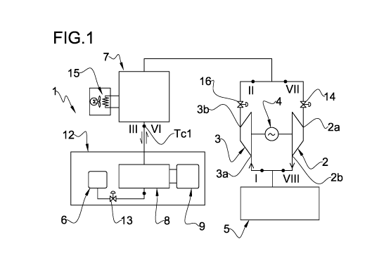
= figure 1 schematically illustrates a plant for energy storage according
to the
present invention;
= figures 2A and 2B are schematic representations of an element of figure 1
in respective operative configurations;
= figure 3 is a T-S diagram relative to the thermodynamic transformation
operated in the plant of figure 1;
= figure 3A is an enlargement of a part of the T-S diagram of figure 3;
= figure 4 is an enlargement of figure 3;
= figure 5 illustrates the enlargement of figure 4 according to an
operative
lo mode;
= figure 6 illustrates the enlargement of figure 4 according to a different
operative mode;
= figure 7A illustrates a portion of the plant of figure 1 according to an
embodiment variant;
= figure 7B illustrates a different variant of the portion of figure 7A;
= figure 8 illustrates the portion of figure 7A according to a further
embodiment variant;
= figures 9 - 12 illustrate respective embodiments of the plant of figure
1.
Detailed description
With reference to the enclosed figures, reference number 1 overall indicates a
plant for energy storage according to the present invention. The plant 1
operates
for example with a working fluid WF different from atmospheric air, e.g.
carbon
dioxide (CO2). For example, the plant 1 operates with a working fluid WF which
has the following chemical-physical properties: critical temperature comprised
between 0 C and 200 C, density at 25 C comprised between 0.5 kg/m3 and 10
kg/m3. For example, the working fluid selected from the group comprising:
carbon
dioxide, mixtures of CO2 and other substances, SF6, N20 that are pure or in a
mixture.
The plant 1 is configured for carrying out a closed cyclic thermodynamic
transformation (CTT), first in one direction in a charge configuration/phase
and
then in an opposite direction in a discharge configuration/phase, wherein in
the
CA 03200727 2023-05-03
WO 2022/101727
PCT/IB2021/059917
17
charge configuration the plant 1 accumulates heat and pressure and in the
discharge configuration generates electrical and/or mechanical energy.
With reference to figure 1, the plant 1 comprises an expander defined by a
turbine
2, configured for expanding the working fluid WF, and a compressor 3 of rotary
type (turbocharger), configured to compress the working fluid WF.
The compressor 3 and the turbine 2 are connected to a same motor-generator 4
through respective non-illustrated transmissions, for example through
connection
devices of friction type, which allow connecting and disconnecting upon
command
the turbine 2 and/or the compressor 3 to/from the motor-generator 4.
lo The plant 1 comprises a casing 5 configured for storing the working
fluid WF in
gaseous phase and in pressure equilibrium with the atmosphere. The casing 5 is
for example defined by a pressure-balloon made of flexible material, for
example
made of PVC coated polyester fabric. The pressure-balloon is preferably
arranged
on the surface and not in subterranean caverns and is externally in contact
with
the atmospheric air. At its interior, the pressure-balloon delimits a variable
volume
configured for containing the working fluid WF at atmospheric pressure or
substantially atmospheric pressure, i.e. in pressure equilibrium with the
atmosphere. The casing 5 can also be attained as a gasometer or any other
storage system for gas at low or zero over-pressure.
The plant 1 comprises a tank 6 configured for accumulating the working fluid
WF
in liquid or supercritical phase. The tank 6 is for example made of metal with
an
external wall of cylindrical or spherical shape.
The plant 1 comprises a thermal accumulator 7 (Thermal Energy Storage or TES)
configured to transfer heat to the working fluid WF before it enters in the
turbine 2
or to absorb heat from the working fluid WF exiting from the compressor 3. For
example, the thermal accumulator 7 is a heat regenerator with fixed or movable
bed or it comprises a water, oil or salt circuit with at least one storage
chamber.
The working fluid exchanges heat with a thermal mass (for example cement or
ceramic or metal) of the heat regenerator of heat with fixed or movable bed or
with
water, oil or salt circuit.
CA 03200727 2023-05-03
WO 2022/101727
PCT/IB2021/059917
18
A condenser/evaporator 8 is operatively coupled to the tank 6 and comprises a
heat carrier VT (typically a fluid, e.g. water) configured to transfer heat to
the
working fluid WF or to absorb heat from the working fluid WF.
In the illustrated schematic embodiment, the condenser/evaporator 8 is placed
between the thermal accumulator 7 and the tank 6. The condenser/evaporator 8
is
connected to a basin 9 which contains the heat carrier VT.
Pipes for the working fluid WF, defined for example by a plurality of tubes,
are
operatively interposed between the casing 5 and the tank 6 and connect
together,
directly and/or indirectly, the casing 5, the tank 6, the compressor 3, the
turbine 2,
lo the thermal accumulator 7, the condenser/evaporator 8.
The condenser/evaporator 8 comprises one or more or is formed by one or more
heat exchangers which allow exchanging heat between the working fluid WF
which transits into the respective pipes and the heat carrier VT which flows
into
respective ducts connected to the basin 9. As schematically illustrated in
figures
2A and 2B, the working fluid passes through respective ducts 10 within the
condenser/evaporator 8 and the heat carrier TV passes through respective ducts
11 within the condenser/evaporator 8.
The condenser/evaporator can be a unique exchanger or comprise a single
plurality of exchangers in series or in parallel, capable of operating both
condenser
and as evaporator. Alternatively, the condenser/evaporator 8 comprises a
condensation exchanger (or a single plurality of condensation exchangers in
series or in parallel) and a different evaporation exchanger (or a single
plurality of
evaporation exchangers in series or in parallel).
For example, the condenser/evaporator 8 is of the type with tube bundle and
shell
(shell & tube), per se known and not illustrated herein. The heat carrier VT
can be
contained in the tubes of the tube bundle and the working fluid WF can be
contained in the shell (i.e. between the shell and the tubes) or vice versa.
The system 12 which comprises the tank 6 with the working fluid WF contained
therein, the condenser/evaporator 8, the basin 9 with the heat carrier TV is a
system that is nearly adiabatic with the environment, i.e. it is a closed
system that
substantially does not exchange heat with the environment, except for thermal
losses.
CA 03200727 2023-05-03
WO 2022/101727
PCT/IB2021/059917
19
The pipes delimit a charge path extended from the casing 5 to the tank 6 and a
discharge path extended from the tank 6 to the casing 5.
The plant 1 also comprises adjusting devices configured for actively adjusting
parameters of the working fluid WF. The adjusting devices illustrated in
figure 1
comprise a flow adjustment valve 13 operatively arranged between the tank 6
and
the condenser/evaporator 8, an expander 2 inlet adjustment valve 14, an
exchanger 15 of heat with the environment directly coupled to the thermal
accumulator 7. The plant of figure 1 also comprises an interception valve 16
situated on a delivery of the compressor 3.
lo The plant 1 also comprises a control unit, not illustrated, operatively
connected to
the various elements of the plant 1 itself and configured/programmed for
managing
the operation thereof.
The plant 1 is configured for operating in a charge configuration/phase or in
a
discharge configuration/phase, i.e. for executing a process comprising an
energy
charge phase and an energy generation and discharge phase according to a
closed cyclic thermodynamic transformation CTT. In the charge
configuration/phase, the plant 1 is configured to condense the working fluid
WF by
means of heat absorption by the heat carrier VT (and transfer of heat from the
working fluid) and store said working fluid WF in the liquid or supercritical
phase in
the tank 6. In the discharge configuration/phase, the plant 1 is configured to
evaporate the working fluid starting from the liquid or supercritical phase by
transfer of heat from the heat carrier VT (and heat absorption by the working
fluid).
With reference to figures 1 and 3, in the charge configuration/phase, the
plant 1
starts from a first state in which the working fluid WF in gaseous form is
contained
in the casing 5 at atmospheric pressure or substantially atmospheric pressure
and
at a temperature substantially equal to the ambient temperature Tamb (point
l). The
casing 5, through suitable valves, is placed in communication with an inlet 3a
of
the compressor 3 while the communication with an outlet 2b of the turbine 2 is
blocked. In addition, due to valves, the thermal accumulator 7 is placed in
fluid
communication with an outlet 3b of the compressor 3 and the communication with
an inlet 2a of the turbine 2 is blocked. The motor-generator 4 is coupled to
the
singe compressor 3 and is decoupled from the turbine 2 (which is at rest) and
CA 03200727 2023-05-03
WO 2022/101727
PCT/IB2021/059917
works as a motor for actuating the compressor 3 so as to compress the working
fluid coming from the casing 5.
The working fluid WF is compressed in the compressor 3 and is heated (point
II).
A delivery temperature of the compressor 2 is for example at 400 C. The
working
5 fluid WF then flows through the thermal accumulator 7 which works as
cooler in
order to remove heat from the compressed working fluid WF, cool it (point III,
figures 3 and 3A) and accumulate the thermal energy removed from said working
fluid WF. In point III, i.e. at the entrance into the condenser/evaporator 8,
the
working fluid WF is situated at a condenser inlet temperature Tcl which is
higher
lo than the ambient temperature Tamb.
In the condenser/evaporator 8, which works in this phase as cooler/condenser,
the
working fluid WF transfers heat to the heat carrier TV, is subjected (figure
3A) to a
desuperheating (from the condenser inlet temperature Tcl to a condensation
start
temperature Tc2), followed by the condensation of the working fluid (from the
15 condensation start temperature Tc2 to the condensation end temperature
Tc3),
followed by a supercooling (from the condensation end temperature Tc3 to a
condenser outlet temperature Tc4), up to being situated in point IV. The
working
fluid WF is accumulated in supercooled liquid phase in the tank 6.
The heat carrier TV absorbs heat and is heated from a first heat absorption
start
20 temperature Ti to a second heat absorption end temperature T2. The
temperature
difference T2 - Ti depends on the specific heat of the heat carrier TV, on the
mass
of the heat carrier TV and on the heat which it receives from the working
fluid WF
during condensation phase. When the working fluid WF is at the condenser inlet
temperature Tcl , the heat carrier TV has the first heat absorption start
temperature Ti. When the working fluid WF is at the condenser outlet
temperature
Tc4, the heat carrier TV has the second heat absorption end temperature T2.
According to that illustrated in the non-limiting example of figures 3 and 3A,
the
condenser outlet temperature Tc4, i.e. the temperature at which the working
fluid
WF is accumulated in the tank 6, is higher than the ambient temperature Tamb.
While it is accumulated, the working fluid exchanges heat with the environment
due to thermal losses and is brought to point V at the temperature Tel (figure
3A).
CA 03200727 2023-05-03
WO 2022/101727
PCT/IB2021/059917
21
In the discharge configuration/phase, the plant 1 starts from this state
(point V of
figure 3A). The casing 5, through the valves, is placed in communication with
the
outlet 2b of the turbine 2 while the communication with the inlet 3a of the
compressor 3 is blocked. In addition, by means of the valves, the thermal
accumulator 7 is placed in fluid communication with the inlet 2a of the
turbine 2
and the communication with the outlet 3b of the compressor 3 is blocked. The
motor-generator 4 is coupled to the single turbine 2 and is decoupled from the
compressor 3 (which is at rest) and works as a generator rotated by the
turbine 2
actuated by the expanding working fluid.
The condenser/evaporator 8 works in this phase as heater/evaporator, the heat
carrier TV transfers part of the heat, previously accumulated in the charge
configuration, to the working fluid WF. The working fluid WF is subjected to a
possible heating and/or throttling of the working fluid (from the evaporator
inlet
temperature Tel to an evaporation start temperature Te2), followed by the
evaporation of the working fluid (from the evaporation start temperature Te2
to an
evaporation end temperature Te3), followed by a superheating of the working
fluid
(from the evaporation end temperature Te3 to a temperature at the end of the
superheating / evaporator Te4 outlet), up to being situated at point VI.
The heat carrier TV transfers heat and is cooled by a third heat transfer
start
temperature T3 to a fourth heat transfer end temperature T4. The temperature
difference T3 - T4 depends on the specific heat of the heat carrier TV, on the
mass
of the heat carrier TV and on the heat that is removed therefrom by the
working
fluid WF during the evaporation phase.
When the working fluid WF is at the evaporator inlet temperature Tel, the heat
carrier TV has the third heat transfer start temperature T3. When the working
fluid
WF is at the evaporator outlet temperature Te4, the heat carrier TV has the
fourth
heat transfer end temperature T4.
According to that illustrated in the non-limiting example of figures 3, 3A and
4, the
evaporator inlet temperature Tel and the evaporation start temperature Te2
coincide and the second temperature T2 and the third temperature T3 of the
heat
carrier TV coincide so that the system does not significantly dissipate heat.
In
addition, in order to maximize the performance of the system, it is desirable
to
CA 03200727 2023-05-03
WO 2022/101727
PCT/IB2021/059917
22
have the evaporation pressure Pe as high as possible. If follows that, during
the
evaporation phase, the heat of evaporation Qevap removed is smaller than the
heat
of condensation Qpand during the condensation phase and hence the temperature
T4 will be higher than the temperature Ti.
Once exited from the condenser/evaporator 8, the working fluid WF traverses
the
thermal accumulator 7 which now works as heater and transfers further heat,
previously accumulated in the charge configuration, to the working fluid WF
and it
heats it. The heated working fluid WF enters into the turbine 2, is expanded
and is
cooled (point VIII of figure 3) and causes the rotation of the turbine 2. The
turbine
io 2, rotated by the heated working fluid, drives the motor-generator 4
which works
as generator and generates electrical energy. The working fluid WF exiting
from
the turbine 2 returns into the casing 5 at atmospheric pressure or
substantially
atmospheric pressure (point VII of figure 3).
Once one cycle has terminated, the plant 1 - in order to prepare for a new
cycle -
must bring the heat carrier back to the first temperature Ti, starting from
the
second temperature T2. There is thus the need to extract heat from the heat
carrier TV and transfer it to the environment. The first temperature Ti must
be
close to or higher than the ambient temperature Tamb so that the heat is
transferred
outside the system.
In accordance with the plant and the process of the present invention,
provision is
made for adjusting one or more parameters of the working fluid WF related to
the
condensation and/or to the evaporation, through the abovementioned adjusting
devices, in order to control the temperature of the heat carrier TV and to
uncouple
said temperature of the heat carrier TV from the ambient temperature Tamb
without
the aid of systems outside the cyclic thermodynamic transformation. In
particular,
the active adjustment of one or more parameters of the working fluid WF allows
carrying out the cyclic thermodynamic transformation (CTT) independent of the
ambient temperature Tamb and without the aid of devices outside the cyclic
thermodynamic transformation (CTT) adapted to create artificial sources at a
temperature higher or lower than the ambient temperature Tamb. The system
which
contains the heat carrier TV, in an entirely natural manner, will transfer
heat to the
CA 03200727 2023-05-03
WO 2022/101727
PCT/IB2021/059917
23
environment or will receive heat from the environment depending on whether it
is
at a temperature higher or lower than the ambient temperature Tamb.
Hence the present invention also relates to a method for controlling a heat
carrier
in the process and/or in the plant for energy storage.
The working fluid WF parameters that can be actively adjusted are the
following:
condenser inlet temperature Tcl and/or condensation start temperature Tc2
and/or condensation end temperature Tc3 and/or condenser outlet temperature
Tc4, evaporator inlet temperature Tel and/or evaporation start temperature Te2
and/or evaporation end temperature Te3 and/or evaporator outlet temperature
Te4
lo and/or evaporation pressure Pe.
Example 1 ¨ figure 5
If it is desired to have an excess of heat during the condensation phase with
respect to the evaporation phase (n \ ¨cond - Qevap > 0), the following
adjustments can
be executed.
During the condensation phase:
- increasing the inlet temperature at the condenser Tcl, i.e. increasing a
difference between the inlet temperature at the condenser Tcl and the
condensation start temperature Tc2 so as to increase the heat of the
desuperheating sub-phase;
- decreasing the outlet temperature of the condenser Tc4 and hence
increasing a difference between condensation end temperature Tc3 and the
condenser outlet temperature Tc4 so as to increase the heat to be removed
during the supercooling sub-phase.
In this manner, with respect to that illustrated in figure 4, the second
temperature
T2 of the heat carrier TV increases, given the same condensation pressure Pe
conditions, due to the higher quantity of heat to be removed.
During the evaporation phase:
CA 03200727 2023-05-03
WO 2022/101727
PCT/IB2021/059917
24
- increasing the evaporation pressure Pe (and hence the evaporator inlet
temperature Tel and/or the evaporation start temperature Te2 and/or the
evaporation end temperature Te3) so as to reduce the heat of evaporation
in the evaporation sub-phase;
-
decreasing a difference between the evaporation end temperature Te3 and
the evaporator outlet temperature Te4 in order to reduce the superheating
heat.
In this manner, with respect to that illustrated in figure 4, the fourth
temperature T4
of the heat carrier TV increases, given the same conditions, due to the lower
quantity of heat removed and due to the higher third temperature T3 of the
heat
carrier TV.
Example 2 ¨ figure 6
If it is desired to have an excess of heat during the evaporation phase with
respect
to the condensation phase (Qcond - Qevap < 0), the following adjustments can
be
executed.
During the condensation phase:
- decreasing the condenser inlet temperature Tcl or decreasing a difference
between the condenser inlet temperature Tcl and the condensation start
temperature Tc2, in order to reduce the heat of the desuperheating sub-
phase;
- increasing the condenser outlet temperature Tc4 or decreasing a difference
between the condensation end temperature Tc3 and the condenser outlet
temperature Tc4, in order to reduce the heat to be removed during the
supercooling sub-phase.
In this manner, with respect to that illustrated in figure 4, the second
temperature
T2 of the heat carrier will be lower, given the same conditions, due to the
lower
quantity of heat to be removed.
CA 03200727 2023-05-03
WO 2022/101727
PCT/IB2021/059917
During the evaporation phase:
- decreasing the evaporation pressure Pe (and hence the evaporator inlet
temperature Tel and/or the evaporation start temperature Te2 and/or the
evaporation end temperature Te3), in order to increase the heat of
5 evaporation in the evaporation sub-phase since the latent heat
increases
with the decrease of the pressure (bell shape of figure 3A);
- increasing a difference between the evaporation end temperature Te3 and
the evaporator outlet temperature Te4, in order to increase the superheating
heat.
In this manner, with respect to that illustrated in figure 4, the fourth
temperature T4
of the heat carrier TV will be lower, given the same conditions, due to the
higher
quantity of heat removed and due to the lower third temperature T3 of the heat
carrier TV.
The control unit is operatively coupled to the adjusting devices and is
configured
and/or programmed to adjust said one or more parameters of the working fluid.
The evaporation pressure Pe of the working fluid WF (and hence the evaporator
inlet temperature Tel and/or the evaporation start temperature Te2 and/or the
evaporation end temperature Te3) can be adjusted through the flow adjustment
valve 13 and possibly also through the expander 2 inlet adjustment valve 14.
By
acting on the adjustment of the flow rate of the working fluid WF and with the
adjustment of the expander 2 inlet adjustment valve 14, in accordance with the
flow rate of the heat carrier fluid TV, it is possible to obtain the desired
effect in
various modes. For example, one mode is that in which the expander 2 inlet
valve
14 adjusts the pressure upstream, i.e. at the evaporator 8. In this case, if
the
expander 2 inlet valve 14 is not completely open, the flow adjustment valve 13
for
adjusting the flow acts in order to adjust the power and the expander 2 inlet
valve
14 defines the evaporation pressure Pe. If the expander 2 inlet valve 14 is
completely open, the evaporation pressure Pe is dependent on the flow that is
adjusted by the flow adjustment valve 13.
The condenser outlet temperature Tc4 can be adjusted in various modes.
CA 03200727 2023-05-03
WO 2022/101727
PCT/IB2021/059917
26
In one embodiment, the condenser/evaporator 8 comprises a supercooling
exchanger specifically dedicated to cooling the working fluid WF from the
condensation end temperature Tc3 to the condenser outlet temperature Tc4
(supercooling). In this case, the condenser outlet temperature Tc4 can be
adjusted
by adjusting a flow rate of the heat carrier TV in the supercooling exchanger.
Such
flow rate of the heat carrier TV can be adjusted between a maximum flow rate
and
a zero flow rate (with complete bypass of the supercooling exchanger). The
maximum flow rate allows having the condenser outlet temperature Tc4 identical
to or slightly higher than the first temperature Ti of the heat carrier TV and
having
lo the maximum removal of thermal heat. The zero flow rate allows having
the
condenser outlet temperature Tc4 equal to the condensation end temperature Tc3
and not having removal of thermal heat.
If the condenser/evaporator 8 is a single exchanger of the type with tube
bundle
and shell (shell & tube), with the heat carrier contained in the tubes of the
tube
bundle and the working fluid WF contained between the tubes and the shell, the
condenser outlet temperature Tc4 is adjusted by adjusting a level of the
working
fluid WF in the shell (and/or by selecting how many tubes and hence how much
surface of the exchanger to be dedicated to supercooling). Such level of the
working fluid WF can be adjusted between a maximum level (design) and a
minimum level below the tubes. The maximum level allows having the condenser
outlet temperature Tc4 identical to or slightly higher than the first
temperature Ti
of the heat carrier TV and having the maximum removal of thermal heat, having
a
part of the tubes of the exchanger which exchange heat with the condensate and
hence which supercool the condensate. The minimum level below the tubes allows
having the condenser outlet temperature Tc4 equal to the condensation end
temperature Tc3 and not having the removal of thermal heat. Indeed, in this
case,
not having any tube of the exchanger that exchanges heat with the condensate,
one prevents removing heat from the condensate and the condensate is not
supercooled.
If the condenser/evaporator 8 is a single exchanger of the type with tube
bundle
and shell (shell & tube), with the working fluid WF contained in the tubes of
the
tube bundle and the heat carrier TV contained between the tubes and the shell,
CA 03200727 2023-05-03
WO 2022/101727
PCT/IB2021/059917
27
the condenser outlet temperature Tc4 is adjusted by adjusting a flow rate of
the
heat carrier TV in the tubes (i.e. by increasing the heat exchange and hence
the
capacity of removing heat from the working fluid WF). In this case the heat
carrier
TV condenses within the tubes. Such flow rate of the heat carrier TV can be
adjusted between a maximum flow rate (design) and a minimum flow rate. The
maximum flow rate allows having the condenser outlet temperature Tc4 identical
to or slightly higher than the first temperature Ti of the heat carrier TV and
having
the maximum removal of thermal heat. The minimum flow rate allows having the
condenser outlet temperature Tc4 equal to or slightly lower than the
condensation
lo end temperature Tc3 and not having removal of thermal heat after
condensation.
The temperature at the end of superheating / evaporator Te4 outlet can be
adjusted in various modes.
In one embodiment, the condenser/evaporator 8 comprises a superheating
exchanger dedicated to superheating the working fluid WF from the evaporation
end temperature Te3 to the evaporator outlet temperature Te4 (superheating).
In
this case, the evaporator outlet temperature Te4 can be adjusted by adjusting
a
flow rate of the heat carrier TV in the superheating exchanger. Such flow rate
of
the heat carrier TV can be adjusted between a maximum flow rate and a zero
flow
rate (with complete bypass of the superheating exchanger). The maximum flow
rate allows having the evaporator outlet temperature Te4 identical to or
slightly
lower than the third temperature T3 of the heat carrier TV and having the
maximum transfer of thermal heat. The zero flow rate allows having the
evaporator
outlet temperature Te4 equal to the evaporation end temperature Te3 and not
having transfer of thermal heat.
If the condenser/evaporator 8 is a single exchanger of the type with tube
bundle
and shell (shell & tube), with the heat carrier contained in the tubes of the
tube
bundle and the working fluid WF contained between the tubes and the shell, the
evaporator outlet temperature Te4 is adjusted by adjusting a level of the
working
fluid WF in the shell (and/or by selecting how many tubes and hence how much
surface of the exchanger to be dedicated to superheating). Such level of the
working fluid WF can be adjusted between a minimum level (design) and a
maximum level above tubes. The minimum level allows having the evaporator
CA 03200727 2023-05-03
WO 2022/101727
PCT/IB2021/059917
28
outlet temperature Te4 identical to or slightly lower than the third
temperature T3
of the heat carrier TV and having the maximum transfer of thermal heat, since
a
part of the tubes of the exchanger exchange heat with the vapor and hence
overheat the vapor. The maximum level above the tubes allows having the
evaporator outlet temperature Te4 equal to the evaporation end temperature Te3
and not having transfer of thermal heat. Indeed, in this case, not having any
tube
of the exchanger uncovered which exchanges heat with the vapor, one prevents
superheating the vapor.
If the condenser/evaporator 8 is a single exchanger of the type with tube
bundle
io and shell (shell & tube), with the working fluid WF contained in the
tubes of the
tube bundle and the heat carrier TV contained between the tubes and the shell,
the evaporator outlet temperature Te4 is adjusted by adjusting a flow rate of
the
heat carrier TV in the tubes (i.e. by increasing the heat exchange and hence
the
capacity to transfer heat to the working fluid WF). In this case the working
fluid WF
evaporates and is overheated within the tubes. Such flow rate of the heat
carrier
TV can be adjusted between a maximum flow rate (design) and a minimum flow
rate. The maximum flow rate (design) allows having the evaporator outlet
temperature Te4 identical to or slightly lower than the third temperature T3
of the
heat carrier TV and having the maximum transfer of thermal heat. The minimum
flow rate allows having the evaporator outlet temperature Te4 identical to or
slightly higher than the evaporation end temperature Te3 and not having
transfer
of thermal heat after evaporation.
The condenser inlet temperature Tc1 is adjusted through the exchanger 15 of
heat
with the environment coupled to the thermal accumulator 7. The exchanger 15 of
heat with the environment provides for exchanging with the external
environment
part of the heat of the working fluid WF that is accumulated or transits in
the
thermal accumulator 7 in the charge configuration/phase.
The exchanger 15 of heat with the environment illustrated in figure 1
comprises a
circuit with water and a radiator part of the circuit, provided with a fan. In
embodiment variants, not illustrated in detail, the exchanger 15 can be of the
type
with direct exchange, in the sense that the working fluid WF passes into the
tubes
and transfers/takes heat directly from the air. As a function of where the
circuit is
CA 03200727 2023-05-03
WO 2022/101727
PCT/IB2021/059917
29
positioned in the thermal accumulator 7, it is possible to remove heat from
the
thermal accumulator 7 and from the working fluid WF and transfer it to the
environment or absorb heat from the environment and transfer it to the thermal
accumulator 7 and to the working fluid WF. In this manner, the temperature
downstream of the thermal accumulator 7, i.e. the condenser inlet temperature
Tc1, can be adjusted.
In the plant illustrated in figure 1, the suction pressure of the compressor 3
is fixed
and is nearly identical to the atmospheric pressure, except for the load
losses. The
lo delivery pressure instead is dependent on the condensation pressure plus
the
possible load losses. The delivery temperature of the compressor 3 is directly
dependent on the delivery pressure and on the performance of the compressor 3
itself. The higher the delivery pressure, the higher the temperature;
additionally,
greater pressure jump implies a lower performance of the machine.
The delivery pressure, if it was in some way tied to the ambient temperature
Tamb,
would in some way be predefined/constrained by the climactic conditions where
the system is installed. Through the above-described control of the
condenser/evaporator 8, it is instead possible to define, independent of the
environment conditions, the delivery pressure of the compressor 3.
This is an extremely advantageous characteristic, since the compressor 3 can:
- always work close to the design point; indeed, being uncoupled from the
ambient temperature, variations due to the daily and seasonal change of
temperature are not sustained, thus allowing working in the points of
maximum performance of the compressor 3;
- limit the operating pressure, allowing the use of machines with main
geometry of axial type;
- limit the maximum operating temperature; indeed in hot climates, the
condensation pressure would be high and also the delivery temperature
would increase, involving selection of "costly" materials both for the
construction of the machine and for the thermal accumulator placed
downstream of the compressor; by adjusting the pressure of the condenser
it is instead possible to maintain a sufficiently low pressure and hence a
CA 03200727 2023-05-03
WO 2022/101727
PCT/IB2021/059917
reasonable temperature that allows a selection of common materials,
typically lower than 450 C, preferably lower than 375 C for the thermal
accumulator but also for pipes, connections, valves and all that which lies
downstream of the compressor, including the expander;
5 -
enable the condensation even in places where the climate is extremely
unfavorable, such to have the ambient temperature higher than the critical
temperature of the working fluid; without a control and a free selection of
the condensation pressure, it would be impossible to attain the system
where condensation is provided for;
lo -
have an additional variable for defining the power of absorption of the
compressor; indeed, the power of the compressor depends on the pressure
pump and on the processed flow rate; while on the flow rate it is possible to
act on the variable geometries of the machines, though within a limited
range, by acting on the delivery pressure of the machine the adjustable field
15 ("power") increases considerably;
- the possibility to maintain constant the delivery pressure, independent
of
the surrounding conditions, allows being able to select a more "rigid" but
more efficient machine type;
- the possibility to be able to select the delivery pressure allows the
20
installation also at altitudes where the atmospheric pressure is lower, also
because it would increase the pressure pump of the compressor.
Figure 7A illustrates a portion of the plant 1 according to an embodiment in
which
the thermal accumulator 7 comprises a thermal fluid and an auxiliary exchanger
18, wherein the auxiliary exchanger 18 is operatively coupled to the pipes and
is
25
placed between the compressor 2 and the condenser/evaporator 8. The thermal
accumulator 7 comprises a first tank 19A (hot storage of the thermal fluid), a
second tank 19B (cold storage of the thermal fluid) connected together through
as
suitable piping 17. The auxiliary exchanger 18 is placed between the first
tank 19A
and the second tank 19B. The thermal fluid, for example water, is situated in
the
30
first tank 19A, in the second tank 19B to move through the auxiliary exchanger
18
coupled to the pipes with the working fluid WF. In addition, a first exchanger
15A
of heat with the environment is situated between the first tank 19A and the
CA 03200727 2023-05-03
WO 2022/101727
PCT/IB2021/059917
31
auxiliary exchanger 18, a second exchanger 15B of heat with the environment
situated between the second tank 19B and the auxiliary exchanger 18. The
thermal accumulator 7 thus structured also allows adjusting the condenser
inlet
temperature Tc1.
Figure 7B illustrates a portion of the plant 1 according to an embodiment in
which
the thermal accumulator 7 comprises a thermal fluid and an auxiliary exchanger
18, wherein the auxiliary exchanger 18 is operatively coupled to the pipes and
is
placed between the compressor 2 and the condenser/evaporator 8. The thermal
accumulator 7 comprises a first tank 19A (hot storage of the thermal fluid), a
io second tank 19B (cold storage of the thermal fluid) connected together
through a
suitable piping 17. The auxiliary exchanger 18 is placed between the first
tank 19A
and the second tank 19B. The thermal fluid, for example water, is situated in
the
first tank 19A, in the second tank 19B to move through the auxiliary exchanger
18
coupled to the pipes with the working fluid WF. In addition, a first exchanger
15A
of heat with the environment is situated between that which lies upstream of
the
exchanger 18 and the auxiliary exchanger 18, a second exchanger 15B of heat
with the environment situated between the auxiliary exchanger 18 and the
condenser evaporator. The exchangers 15A and 15B directly exchange heat with
the WF and the environment without intermediate heat carriers. The thermal
accumulator 7 thus structured also allows adjusting the condenser inlet
temperature Tc1.
Figure 8 illustrates a variant of the thermal accumulator 7 of figure 7A, in
which the
thermal fluid is the same heat carrier TV used in the condenser/evaporator 8.
The
thermal accumulator 7 of figure 8 comprises a tank 19 (hot storage of the
thermal
fluid) for the thermal heat carrier/fluid TV in fluid communication with the
basin 9
(cold storage of the thermal fluid) of the heat carrier TV. The first
exchanger 15A of
heat with the environment is situated between the tank 19 and the auxiliary
exchanger 18, the second exchanger 15B of heat with the environment is
situated
between the auxiliary exchanger 18 and the basin 9. One part of the heat
carrier
exiting from the condenser/evaporator 8 (at the second temperature T2) is
picked
up in the charge configuration/phase and stored in the tank 19 after having
absorbed heat from the working fluid WF through the auxiliary exchanger 18. In
CA 03200727 2023-05-03
WO 2022/101727
PCT/IB2021/059917
32
the discharge configuration/phase, such part of the heat carrier is given back
at
the inlet to the condenser/evaporator 8 after having transferred heat to the
working
fluid WF through the auxiliary exchanger 18.
In the solutions illustrated above in figures 7A and 8, it is possible to
adjust the
condenser inlet temperature Tc1 by acting on the thermal accumulator 7,
exporting
heat from or transferring heat to the environment through the first and the
second
exchanger 15A, 15B of heat with the environment. If one wishes to extract
heat, it
will be necessary to act on the phase in which the heat carrier/fluid of the
thermal
accumulator 7 has a temperature higher than the ambient temperature, while
lo instead it will be possible to insert heat in the system on the phase in
which the
heat carrier/fluid is at a temperature lower than the ambient temperature. The
first
exchanger 15A transfers heat to the environment by removing it from the
working
fluid WF (TC1 decreases). The second exchanger 15B transfers heat to the
working fluid WF by removing it from the environment (TC1 increases).
In the case of direct exchange (figure 7B), if one wishes to extract heat, it
will be
necessary to act on the phase in which the WF has a temperature higher than
the
ambient temperature, while instead it will be possible to insert heat in the
system
on the phase in which the WF is at a temperature lower than the ambient
temperature.
Figure 9 illustrates an embodiment of the plant 1 that comprises two
compressors
3', 3" placed in series and two expanders 2', 2" placed in series. The thermal
accumulator comprises a first thermal accumulator 7A that lies interposed
between
the two compressors 3', 3" and the two expanders 2', 2", so that the
compressors
3', 3" are inter-cooled and the expanders 2', 2" are inter-heated. A second
thermal
accumulator 7B is situated as in figure 1. The exchanger 15 of heat with the
environment is directly coupled to the first thermal accumulator 7A and not to
the
second thermal accumulator 7B.
Figure 10 illustrates a variant of the embodiment of the plant 1 of figure 9
(with two
compressors 3', 3" placed in series and two expanders 2', 2" placed in series,
a
first thermal accumulator 7A and a second thermal accumulator 7B).
The first thermal accumulator 7A is divided into two parts and comprises a
first
tank 19A (hot storage of the thermal fluid), a second tank 19B (cold storage
of the
CA 03200727 2023-05-03
WO 2022/101727
PCT/IB2021/059917
33
thermal fluid) connected together and to a first and to a second auxiliary
exchanger 18A, 18B through a suitable piping 17. The first heat exchanger 18A
is
coupled to the pipes of the working fluid WF downstream of the two compressors
3', 3" placed in series (in the charge phase) and upstream of the two
expanders 2',
2" placed in series (in the discharge phase). The second heat exchanger 18B is
interposed between the two compressors 3', 3" (in the charge phase) and
between
the two expanders 2', 2" (in the discharge phase). The heat exchanger 15 with
the
environment is coupled to the piping 17.
The second thermal accumulator 7B comprises a tank 19 for the thermal heat
io carrier/fluid TV in fluid communication with the basin 9 of the heat
carrier TV. A
single exchanger 15 of heat with the environment is situated between the tank
19
and the auxiliary exchanger 18. The auxiliary exchanger 18 is coupled to the
pipes
of the working fluid WF between the condenser/evaporator 8 and the first heat
exchanger 18A.
Figure 11 illustrates a further variant of the embodiment of the plant 1 of
figure 9
(with two compressors 3', 3" placed in series and two expanders 2', 2" placed
in
series, a first thermal accumulator 7A and a second thermal accumulator 7B).
The first thermal accumulator 7A is of "pressurized packed bed" (PPB) type and
an
exchanger 15 of heat with the environment is coupled to the pipes of the
working
fluid WF between said first thermal accumulator 7A and the compressor 3"
placed
more downstream.
The second thermal accumulator 7B comprises a first tank 19A (hot storage of
the
thermal fluid), a second tank 19B (cold storage of the thermal fluid)
connected
together through a suitable piping 17. The auxiliary exchanger 18 is placed
between the first tank 19A and the second tank 19B. In this exemplifying
embodiment, the second thermal accumulator 7B is not provided with an
exchanger 15 of heat with the environment.
Figure 12 illustrates a variant of the embodiment of the plant 1 of figure 11
which
differs from figure 11 due to the fact that the second thermal accumulator 7B
is
substantially identical to that illustrated in figure 10.