Note: Descriptions are shown in the official language in which they were submitted.
WO 2022/118062
PCT/TB2020/061551
Low scattering loss high temperature stable fiber Bragg grating sensor
based on micropore formation and Method for Producing Same
Field of the Invention
mon The present invention relates in general to the inscription of Bragg
gratings in
optical waveguides, and in particular to using femtosecond pulse duration
lasers and
specialized transmission diffractive elements and to a fiber Bragg grating
sensor capable
of measuring temperature, strain, and environment at temperatures up to 1000
C.
Background of the Invention
[0002] Fiber Bragg grating sensors (FBG sensors) are attractive devices for
performing
quasi-distributed temperature and strain measurements along an optical fiber.
Variations
in the spectral response of the FBG result from changes in its period (AG) and
effective
refractive index (neff) due to strains or temperature variations that are
experienced by the
optical fiber when placed in a specific environment. FBG sensors offer
important
advantages over other sensor technologies because of their electrically
passive operation,
immunity to electromagnetic interference (EMI.), high sensitivity, and
multiplexing
capabilities. FBGs are simple, intrinsic sensing elements which traditionally
have been
photo-inscribed into photosensitive Ge-doped silica fiber using ultraviolet
(UV) radiation.
Each FBG sensor has a characteristic retro-reflective Bragg resonance or Bragg
wavelength
(Aa), which is dependent upon the periodicity of the grating photo-inscribed
within the
fiber (i.e., AG) and the effective refractive index of the fundamental core
mode of the optical
fiber (i.e., nor). FBG sensors can be multiplexed in a serial fashion along a
length of single
fiber to produce a quasi-distributed optical fiber sensor array. When embedded
into
composite materials, optical fibers with an array of FBG sensors allow for
distributed
measurements of load, strain, temperature, and vibration of the material
creating what is
commonly referred to as "smart structures" where the health and integrity of
the structure
is monitored on a real-time basis.
[0003] Typically, FBGs are generated by exposing the UV-photosensitive core of
a
germanium-doped (Ge-doped) silica core optical fiber to a spatially modulated
UV laser
beam in order to create refractive index changes in the fiber core that are
permanent at
1
CA 03200760 2023- 5- 31
WO 2022/118062
PC171132020/061551
room temperature. Such a spatially modulated UV beam can be created by using a
two-
beam interference technique as disclosed in US patent number 4,807,950 by
Glenn et al.
or by using a phase mask as disclosed in US patent number 5,367,588 by Hill et
al. The
techniques taught by Glenn and Hill result in FBGs that can be erased at
temperatures
significantly lower than the glass transition temperature and are typically
referred to as
Type I gratings.
[0004] A limitation of the prior-art UV-induced Type I FBGs, especially for
high
temperature sensing applications, is that operation of the FBG sensor at
elevated
temperatures results in the erasure or annealing of the UV-induced color
centers and
densification that are responsible for the induced index change of the FBG. In
fact, for
silica (SiO2) fibers total erasure of the induced index modulation occurs at
1000 'C. Also,
the fiber itself is modified when exposed to such high temperatures in an
oxygen-
containing atmosphere: the fiber can be easily deformed by its own weight,
become brittle
and the core material can diffuse into the cladding.
[0005] Another method for creating permanent photorefractive index changes in
glasses
employs the use of intensive UV beams with fluences (i.e., energy/unit-area
per laser pulse)
that approach those required to produce macroscopic damage of the glass.
Askins etal. in
US patent number 5,400,422 teach a method for producing permanent
photorefractive
index changes in the photosensitive cores of Ge-doped optical fibers with a
single high-
intensity UV laser pulse. Such FBGs, which result from macroscopic damage to
the optical
fiber, can survive temperatures approaching the glass transition temperature
and are
typically referred to as Type II gratings. The high-intensity portions of the
interference
fringes created by two crossed UV beams split from a single UV beam create
localized
damage at the core-cladding interface within the fiber. Because the process
for inducing
index change is one of structural change due to localized physical damage to
the glass,
rather than due to UV photo-induced formation of color center defects, the
induced index
change is more robust and does not decrease at elevated temperatures. In fact,
Askins et
a/. disclose that gratings produced in this way cannot be removed by annealing
until the
fiber or waveguide approaches the material's glass transition temperature. The
drawback
of this approach for induction of index change is that the resultant Bragg
gratings have
2
CA 03200760 2023- 5- 31
WO 2022/118062
PCT/1132020/061551
relatively low refractive index modulations (An =104) and are mechanically
weak since
the effective refractive index change originates from periodic localized
damage at the core-
cladding interface. The damage occurs because for pulses longer than a few
tens of
picoseconds the laser-excited electrons transfer energy to the surrounding
lattice faster than
the thermal diffusion in the material can remove the energy from the volume
that is being
irradiated. Moreover, if the laser pulse continues to feed energy into the
damage site, the
damage can propagate beyond the irradiated zone. Consequently, the spectral
quality of
FBGs written with laser pulse durations greater than a few tens of picoseconds
is often
poor and the scattering loss of such FBGs is high. Scattering loss is defined
as being the
broadband transmission loss that is out-of-band or non-resonant with the Bragg
grating
resonance AB.
[0006] Another method for creating permanent photorefractive index changes in
optical
fiber employs the use of the process of "hydrogen-loading," as taught by
Atkins el al. in
US. Pat. No. 5,287,427, combined with UV-laser exposure of optical fiber that
is
manufactured with a core that is co-doped with fluorine. After the UV exposure
the fiber
undergoes a thermal post treatment at 1000 C in order to induce a chemical
composition
grating as taught by Fokine in US. Pat. No. 6,334,018. These FBGs have often
been
referred to in the literature as thermally regenerated FBGs. As with the
technique taught
by Askins et al., the technique taught by Fokine also has the drawback that
the induced
index change of the FBGs produced in this fashion have relatively low
refractive index
modulations (Art =1 04).
[0007] By using special optical fibers such as silica-based optical fibers
with very high
germanium concentrations in the core, Riant et aL in I Lightwave Tecintal. 15
(8), 1464
(1997) demonstrate that a sustained exposure to an interference pattern
created with pulsed
UV laser light will initially produce a Type I FBG which will erase and then
subsequently
regrow but at a shorter wavelength of the Bragg resonance. This Type of FBG
has been
found to have better thermal stability at 400 C than a Type I FBG and has
been dubbed a
"Type IIA" FBG. The formation of the Type IIA FBG is the result of relaxation
by the
laser beam of high internal stresses present in the fiber due to the
dissimilarities of the fiber
core and cladding materials. The resultant FBG has a negative index change
compared to
3
CA 03200760 2023- 5- 31
WO 2022/118062
PC171132020/061551
the original Type I FBG. The limitation in this approach to writing thermally
stable FBGs
is that the FBG structure erases at temperatures approaching 600 C and is
limited to optical
fibers possessing high internal stresses.
[0008] Another method for creating UV laser induced FBGs with higher thermal
stability
than Type I FBGs is taught by Liu et al. in US Pat. No. 6,907,165, where
sustained
exposure of a hydrogen-loaded Boron-Germanium co-doped optical fiber to a UV
interference pattern results in the formation of a Type I FBG, its subsequent
erasure and
then the formation of what is called a Type IA FBG with better thermal
properties. As in
the approach demonstrated by Riant et al. for Type HA FBGs, sustained exposure
to the
UV laser beam results in Type I grating formation, its erasure and the
formation of another
grating with better thermal stability but with a positive index change. As in
the case of
Type IIA FBGs, this approach requires specialty optical fibers as well as
hydrogen loading
(H2-loading). Furthermore, the induced index change is annealed out at
temperatures
above 500 C.
[0009] The fabrication of high-temperature stable FBGs using ultrafast
infrared radiation
and a phase mask, as taught by Mihailov et al. in US. Pat. No. 6,993,221
results in high
temperature stable FBGs with very high index modulations (An >10-3). For Ge-
doped silica
optical fibers, Smelser et aL showed in Opt. Express., vol. 13, pp. 5377-5386,
(2005), that
these high-temperature stable FBGs are formed as a result of traversing an
intensity
threshold Ail. When using multiple irradiating femtosecond infrared (fs-111)
laser pulses
with beam intensities greater than ith = 4 x 10" W/cm2 in the core region of
the optical
fiber, the formation of thermally stable FBGs that are similar to Type ii UV-
induced FBGs
was observed. In the case of FBGs fabricated using the techniques taught in
US. Pat. No.
6,993,221, the index modulation results from a threshold-type process of
multiphoton
ionization. Recently, Hnatovsky et al. showed in Opt. Lett., vol. 42, pp. 399-
402, 2017
that by utilizing the exposure conditions taught in US. Pat. No. 6,993,221,
form-
birefringent planar self-organized nanostructures are created similar to those
demonstrated
by Shimotsuma etal. in Phys. Rev. Lett., vol. 91, article 247405, 2003.
Although strong
FBGs can be formed using the approach taught in US. Pat. No. 6,993,221, the
underlying
Type H material modification introduces high scattering loss making it
difficult to
4
CA 03200760 2023- 5- 31
WO 2022/118062
PC171132020/061551
concatenate a large number of FBG sensors into a sensor array on a single
length of optical
fiber. The threshold nature of the process also makes it more difficult to
tailor the induced
index profile of the grating in terms of its apodization, reflectivity and
reflection
bandwidth. Using the technique taught by Mihailov et al. in US Pat. No.
7,031,571,
Smelser et al. also showed that very high index modulations (An >10-3) could
be created
with laser beam intensities lower than ith = 4 x 10¹³ W/cm2 that did not
possess high
scattering loss. However these FBGs were not high-temperature stable and the
index
modulation likely arising from color center formation and material
densification, erased at
temperatures > 800 C.
[000101 Smelser et al. in US. Pat. No. 8,272,236 taught that the induction of
FBGs using
multiple fs-IR laser pulses, with each pulse having the intensity below the
single-pulse
intensity threshold for Type II FBG formation, could produce extremely large
index
modulations (M > 3x10). Beside the sustained laser exposures these FBGs
require
photosensitization of the optical fiber to IR radiation, similar to the Type I
FBGs fabrication
method in Ge-doped 1I2-loaded optical fiber taught by Mihailov et al. in US
Pat. No.
7,515,792. Beneficially, the resultant Type II FBGs not only have a portion of
their index
modulation that is thermally stable at 1000 C but also have low scattering
loss. Serious
limitations to this approach result from the requirement of prolonged laser
exposures,
which introduces wear and tear on the inscription laser as well as reducing
the mechanical
strength of the irradiated optical fiber. Additionally, the extra processing
step of
photosensitization can only be applied to Ge-doped fiber and is therefore
ineffective for
other silica-based optical fibers.
[000111 The requirement for use of H2-loading of Ge-doped fiber is eliminated
in the
process taught by Smelser etal. in US Pat. No. 8,402,789 where a Type I FBG is
initially
written using multiple laser pulses at intensities below the single-pulse
intensity threshold
for Type II FBG formation. This pre-conditioning of the optical fiber has the
effect of
lowering the /th for Type II FBG formation by 25%. By lowering the threshold
for multi-
pulse Type II FBG formation and using lower grating inscription laser
intensities, lower-
loss thermally stable Type II FBG are realized.
CA 03200760 2023- 5- 31
WO 2022/118062
PC171132020/061551
[00012] Grobnic et al. in US Patent Publication 2019/0049272 Al teaches a
method to
produce low-loss FBGs possessing high thermal stability using a sequence of
single pulses
of fs-IR radiation focused through a phase mask. The fs pulses emanate from a
regeneratively amplified 'Ti:sapphire laser that has a Fourier transform
limited pulse
duration of 80 fs. However, the pulses used for the FBG inscription are
stretched to 300-
500 fs by introducing a chirp to the pulses. The light intensity in the fiber
core region is
adjusted to be below the single-pulse intensity threshold for Type!! index
change but above
the multi-pulse intensity threshold to induce Type IT index change. The first
few fs-TR
laser pulses form a structure that behaves like a Type I FBG in terms of its
spectral
characteristics and thermal stability. With more fs-IR pulses deposited into
the fiber, the
Type 1 FBG first grows but then starts being erased, which is observed by
monitoring its
spectral characteristics. Grobnic et aL in US Patent Publication 2019/0049272
go on to
teach that if at the point of erasure of the Type I FBG the exposure is
stopped and the fiber
is subsequently annealed above 600 C, a thermally stable grating appears with
the same
Bragg wavelength as the initial Type! FBG but with a very low scattering loss.
An obvious
disadvantage of this process is the necessity to have the extra step of
annealing in order to
realize a thermally stable FBG. Grobnic etal. in US Patent Publication
2019/0049272 also
teaches that with more pulses into the fiber the initially formed Type I FBG
eventually gets
completely spectrally erased and then a regular Type II FBG appears and
eventually grows
to saturation. The scattering loss of such a Type II FBG can exceed 1 dB for a
¨10 mm
long exposed region of the fiber. On first appearance, this Type IT FRG may
seem to be
related to Type IA or Type HA regenerated FBGs as a similar sequence of steps
is required
to create it. Nevertheless, unlike regenerated FBGs, the Type II FRG under
consideration,
which can be more than 20 dB in transmission, neither requires lb-loading or
specialty
fiber nor exhibits any shift in its Bragg wavelength. Its high thermal
stability is likely the
result of simultaneous induction of both Type I and Type II index change that
with
continued exposure leads to the dominance of the Type II index change.
[00013] Besides the earlier discussed phase mask technique there exists
another widely used
laser-writing technique to fabricate FBGs which is based on sequentially
inducing changes
along the fiber core. This point-by-point laser-writing technique was first
described in U.S.
Pat. No. 5,104,209 (1992) to Hill etal., where the FBGs were manufactured by
pre-shaping
6
CA 03200760 2023- 5- 31
WO 2022/118062
PC171132020/061551
a UV laser beam by a narrow slit mask and flashing the UV radiation into the
fiber core
while the fiber was precisely moved between each laser exposure with respect
to the mask.
[000141 Khrushchev etal. in International Pat. No. WO/2005/111677 teach how
sequential
(i.e., point-by-point) laser writing can be implemented with fs-IR beams. In
this case, the
fs-IR pulses are tightly focused inside the fiber core region using a
microscope objective
having a high numerical aperture (NA = 0.45-0.55) and the grating period
produced is
defined by a ratio of the translation speed of the stage on which the fiber is
mounted to the
pulse repetition rate of the laser. Using a variable attenuator the focused
intensity can be
adjusted to slightly alter the refractive index (i.e., Type I modification) in
the fiber core
region without causing permanent optical damage at lower intensity settings or
produce
permanent optical damage (i.e., Type 11 modification) in the core region at
higher
intensities. The permanent optical damage is produced with single laser pulses
and is
assumed to consist of voids surrounded by densified material. The effective
refractive
index in the optical fiber (or waveguide) is locally affected by the presence
of a void in its
vicinity. Even though Khrushchev etal. do not explicitly show the presence of
voids in the
core region, there exists extensive literature corroborating the formation of
voids in
transparent bulk materials by means of tightly focused fs-1R radiation, for
example, Glezer
etal. in in U.S. Pat. No. 5,761,111 (1998), Schaffer et al . in U.S. Pat. No.
7,568,365 B2
(2009). The physics of the formation of fs-light-induced voids in transparent
bulk materials
is discussed in detail by Cramaly et at in Phys. Rev. R vol. 73, pp. 214101
(2006).
[00015] Khrushchev etal. in International Pat No. W012005/111677 also note
that voids,
which underlie Type II modification in this case, are preferably be positioned
slightly
outside of the core. In such a location the voids do not introduce significant
losses to the
transmitted light due to strong scattering, whereas the material surrounding
the voids
intercepts the core and thus changes its effective refractive index.
Alternatively, in order to
have high-contrast change of effective refractive index Aneff at the expense
of higher
scattering loss, voids can be formed inside the core. In this case, according
to Martinez et
al. in IEEE Photonics Technot Lett. Vol. 18, pp. 2266 (2006), Aslund et al. in
Opt. Express
vol. 16, pp. 14248 (2008) and Williams etal. in Opt. Express vol. 20, pp.
13451 (2012),
the scattering loss of the resultant Type-II FBGs is in the range from 104 dB
to 2x 10⁻³ dB
7
CA 03200760 2023- 5- 31
WO 2022/118062
PCT/1132020/061551
per single void, i.e. per grating period, depending on the laser-writing
conditions. Such
losses translate into ¨1 dB per the resultant Type 11 FBG at the best, which
severely limits
the ability to concatenate many 1000 C-resistant FBGs inside one fiber for
quasi-
distributed sensing.
[00016] Taylor et al. in US Patent 7,438,824, teach a method of producing
thermally stable
FBGs that utilize a variation of the point-by-point technique. Taylor et al.
use multiple
femtosecond pulses that have intensities lower than the single-pulse intensity
threshold
required to produce a microvoid. In the case of Taylor et al., each Bragg
grating plane is
created by a superposition of pulses that causes an index change that is the
result of the
formation of self-organized nanogratings within the Bragg grating plane. The
resultant
index change of this FBG is thermally stable up to 1000 C but also creates
high scattering
loss as in the aforementioned methods of Khrushchev, Aslund and Williams.
[00017] To summarize, FBGs manufactured using infrared (ER) femtosecond lasers
and the
phase mask technique can be made thermally stable up to the glass transition
temperature
of the fiber into which they are written, which in the case of silica-based
optical fibers is
typically more than 1000 'C. Generally, in order to make an FBG 1000 C-
resistant, the
laser-induced transformations in the fiber material need to be strong (i.e.,
laser-induced
damage), which requires high laser intensities and exposures with multiple
laser pulses.
Because of the laser-induced damage in the fiber core, the resultant FBGs
suffer from high
scattering loss making it difficult to concatenate more than a few tens of
such FBGs on a
single fiber in order to fabricate a distributed fiber-optic sensor array for
operation in
extreme or high temperature environments. Optical losses can be reduced by
using lower
intensities and applying elaborate multi-pulse laser exposure protocols
followed by
annealing of the resultant FBGs at high temperature, which introduces wear and
tear on the
inscription laser as well as reduces the mechanical strength of the irradiated
optical fiber.
[00018] As discussed above, low loss high temperature stable (up to 1000 C)
sensors based
on FBGs can be manufactured using high-power ultraviolet (UV) sources and the
phase
mask technique. However, this approach requires hydrogen loading techniques,
customized optical fibers and careful annealing of the resultant FBGs in a
furnace
8
CA 03200760 2023- 5- 31
WO 2022/118062
PC171132020/061551
according to a specific recipe, which makes the whole process expensive and
cumbersome
in an industrial manufacturing environment. Even though regenerated FBGs
produced
according to this procedure (referred to in the art as "regenerated gratings")
can withstand
1000 C and large numbers of such FBGs can be concatenated on a single fiber,
they have
very low reflectivities and are often of poor spectral quality.
[00019] Conversely, high temperature stable (up to 1000 C) FBG sensors with
relatively
low losses and good spectral characteristics can be manufactured using IR
femtosecond
lasers and the point-by-point writing technique. In this case, the pulses are
tightly focused
inside the fiber core region and the grating planes of the FBG are produced
one at a time
by firing a laser pulse into the fiber core and then translating the fiber to
a new position to
write another grating plane. The permanent optical damage inside the grating
consists of
voids surrounded by densified material. The losses in the fiber associated
with this
inscription process limit the number of FBGs that can be concatenated on a
single fiber to
a few hundred at the best.
[00020] It is an object of this invention to overcome the aforementioned
limitations within
the prior art.
Summary of the Invention
[00021] The inventors have discovered that 1000 C-resistant FBGs with
extremely low
scattering loss - less than 10-5 dB per grating period - can be fabricated in
silica fibers by
utilizing the phase mask technique for grating inscription using a fs-IR laser
to induce Type
II modification in the fiber core. To improve the uniformity of the light
intensity in the
line-shaped laser focus along the fiber core, a fs-IR inscription beam with a
quasi-flat-top
intensity distribution may be used. Scanning electron microscopy (SEM) reveals
that for
single-pulse irradiation every grating plane of the FBG produced under these
conditions,
as seen by light guided in the fiber, consists of a highly elongated micropore
embedded
within a narrow region of resolidified glass. Thus, the phase mask technique
combined
with a fs-IR laser can be used to fabricate FBGs that possess thermal and
spectral
characteristics of highly localized FBGs produced by the point-by-point
technique but have
a much lower scattering loss. The latter aspect permits multiple hundreds of
Type II FBGs
to be concatenated in a single fiber, which is important for quasi-distributed
sensing in
9
CA 03200760 2023- 5- 31
WO 2022/118062
PC171132020/061551
harsh environments. Additionally, the invention is highly useful for mass
production since
laser writing based on the phase mask technique i) is generally very robust
and reproducible
and ii) represents parallel laser writing as opposed to sequential laser
writing based on the
point-by-point technique. The latter important aspect can be exemplified as
follows: using
the phase mask teclunque with a laser beam having a quasi-flat-top intensity
distribution,
many virtually identical grating planes (individual elongated micropores)
spaced, for
instance, by 500 mu can be created along the fiber core with a single laser
pulse. For a
Bragg grating that is 1 cm in length, this constitutes 20,000 grating planes
or individual
micropores. On the other hand, the laser needs to be fired 20,000 times and
the fiber
translated by 500 nanometers between each laser shot with a sub-nanometer
precision if
the point-by-point technique is used to produce a similar Bragg grating.
1900221 As set further below, a method is provided for method for inscribing a
Bragg grating
in an optical waveguide, comprising the steps of: providing electromagnetic
radiation from
an ultrashort pulse duration laser; providing a focusing optical element to
focus the
electromagnetic radiation from an ultrashort pulse duration laser; providing a
diffractive
optical element that when exposed to the focused electromagnetic radiation
generates a
beam on the optical waveguide having an interference pattern; and irradiating
the optical
waveguide with the electromagnetic radiation to form a Bragg grating, the
electromagnetic
radiation incident on the optical waveguide being sufficiently intensive to
cause a
permanent (Type II) change in the index of refraction within multiple Bragg
grating planes
in the core of the optical waveguide resulting from at least one in icropore.
[00023] Additionally, an apparatus is set forth for inscribing a Bragg grating
in an optical
waveguide, comprising: an ultrashort pulse duration laser for providing
electromagnetic
radiation; a focusing optical element to focus the electromagnetic radiation
from an
ultrashort pulse duration laser; and a diffractive optical element that when
exposed to the
focused electromagnetic radiation from the focusing optical element produces
an
interference pattern in the optical waveguide, wherein positioning the optical
waveguide at
a distance with respect to the diffractive optical element along the
propagation direction of
the electromagnetic radiation where the confocal parameter of line-shaped
laser focus is
smallest and the peak intensity in the focus is highest causes the of i)
negative spherical
aberration and conical diffraction caused by the diffractive optical element
and ii)
CA 03200760 2023- 5- 31
WO 2022/118062
PC171132020/061551
chromatic aberration of the focusing optical element and chromatic dispersion
of the
diffractive optical element to substantially or completely cancel each other
out; and
[00024] wherein irradiating the optical waveguide with the electromagnetic
radiation forms
a Bragg grating, the electromagnetic radiation incident on the optical
waveguide being
sufficiently intensive to cause permanent (Type El) change in the index of
refraction within
multiple Bragg grating planes in the core of the optical waveguide resulting
from at least
one micropore when exposed to one of either a single laser pulse or a
plurality of laser
pulses, wherein said plurality is equal or less than ten.
[00025] In the present application, references to "a permanent change in an
index of
refraction within a core of the optical waveguide" represent the formation of
a grating that
is stable at a temperature up to just below the glass transition temperature
of the material
forming the optical waveguide being inscribed with the Bragg grating. This is
also referred
to herein and in the art as a Type 11 Bragg grating. In one embodiment, where
the
waveguide is a silica-based fiber, and a permanent change in the index of
refraction within
a core of the optical waveguide is one which is stable at temperatures of up
to 1000 C. In
other embodiments, where the optical waveguide comprises a different material
(e.g.
crystalline sapphire), the temperature may be higher than 1000 C. Also, in the
present
application, references to "Bragg grating plane" represents a localized
refractive index
variation that is seen by the guided modes propagating along the fiber as
being a grating
plane.
[00026] These together with other aspects and advantages, as well as a
discussion of the
prior art, are more fully set forth below, reference being had to the
accompanying drawings
forming a part hereof, wherein like numerals refer to like parts throughout.
Brief Description of Drawings
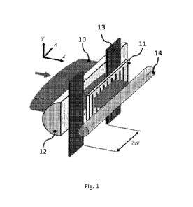
[00027] Fig. 1 depicts an interferometric setup based on the phase mask
technique for the
inscription of a fiber Bragg grating in an optical fiber, according to an
exemplary
embodiment.
[00028] Fig. 2 denotes the orientation of the electric field vector E of the
pulses (i.e., pulse
polarization) with respect to the optical fiber of Fig. 1.
[00029] Fig. 3, comprising Figs. 3(a) and 3(b), shows SEM images of
modification in the
core of the optical fiber induced by a single laser pulse, where Fig. 3(a)
denotes an SEM
11
CA 03200760 2023- 5- 31
WO 2022/118062
PCT/1B2020/061551
image in backscattered electrons and Fig. 3(b) denotes an SEM image in
secondary
electrons.
[00030] Fig. 4, comprising Figs. 4(a) and 4(b), shows SEM images of
modification in the
core of the optical fiber induced by five laser pulses, where Fig. 4(a)
denotes an SEM image
in backscattered electrons and Fig. 4(a) denotes an SEM image in secondary
electrons.
Detailed Description of the Invention
[000311 Fig. 1 shows a linearly polarized femtosecond beam 10 generated, for
example, by
a regeneratively amplified Ti:sapphire femtosecond laser system with transform
limited 80
fs pulses and operated at an 800 nm wavelength. The beam 10 is expanded ¨3.5
times in
the horizontal plane (i.e., along the x-axis, Fig. 1) and focused through a
zeroth-order-
nulled holographic phase mask 11 with a pitch A = 1.07 pin (mask grooves are
aligned
along the y-axis) using a piano-convex cylindrical lens 12 having its curved
surface
designed to correct spherical aberration in one dimension. The effective
numerical aperture
of the cylindrical lens 12 in the yz-plane is estimated at 0.25. The beam
expansion is used
to produce a quasi-flat-top intensity distribution along the x-axis at the
cylindrical lens 12.
A slit 13 of width 2w 15 mm is aligned along they-axis and placed between the
piano-
convex cylindrical lens 12 and the phase mask 11, as depicted in Fig. 1.
Optical fiber 14
(for example STAF-28 fiber manufactured by Corning Incorporated) with its
protective
coating removed, is placed z;300 gm away from the phase mask 11 where the peak
intensity
in the focus is highest. The location of the highest peak intensity may be
determined using
the technique taught by Abdukeritn etal. in Opt. Express vol. 27, pp. 32536-
32555 (2019),
incorporated herein by reference. To inscribe FBGs, the regeneratively
amplified
Ti:sapphire femtosecond laser system is operated at 1 Hz and the pulses are
fired at the
optical fiber 14 one at a time using a synchronized shutter. The morphology of
the laser-
induced modification in the fiber core 21 is revealed using scanning electron
microscopy
(SEM) on fiber samples cleaved along the yz-plane in the middle of the
respective FI3Gs,
as discussed below.
[00032] Fig. 2 denotes the orientation of the electric field vector E of the
pulses (i.e., pulse
polarization) with respect to the optical fiber, according to an aspect of
this specification.
12
CA 03200760 2023- 5- 31
WO 2022/118062
PCT/1B2020/061551
The fiber axis is defined as the x-axis, while the yz-plane denotes the cross
section of the
fiber.
[000331 Abdukerim el al. in Opt. Lett., vol. 45, pp 443-446(2020) show that
the peak laser
intensity at the focus (i.e., at the center of the two-beam interference
pattern produced by
the phase mask 11) in the fiber core 21 can be calculated using
2 PE
I -
(I)
re ra y '
where 14 is the laser pulse energy, r is the pulse duration (full-width half-
maximum), and
2cox and 2coy are focal spot sizes (at the 11e2-intensity level of the
Gaussian intensity profile)
along the x-axis and y-axis inside the fiber, respectively. The x-axis is
parallel to the fiber
axis and the mask grooves are aligned along the y-axis. The scaling
coefficient p is a
product of three factors: p= p11u2p3. The constant pi is related to the pulse
shape, being pi
= 0.88 for sech2-shaped laser pulses. The coefficient p2 accounts for the
polarization-
dependent intensity distribution at the focus of the cylindrical lens 12. If
there are no losses
associated with Fresnel reflection at the front surface of the optical fiber
14 and the phase
mask 11 has a 100% diffraction efficiency, the variation of the focal peak
intensity along
the x-axis at the fiber core 21 can be written as
/ (x) = /0[1 + cos(-)]
A (2)
when the laser pulse polarization E (Fig. 2) is aligned along the y-axis (y-
polarization) and
as
(x) = /0[1+ cos(2O) cos(-42-1)] (2a)
when the laser pulse polarization .E is aligned along the x-axis (x-
polarization). In Eqs. (2)
and (2a), Jo is the focal peak intensity in the incident beam 10 if it is
focused inside the
fiber without the phase mask in the beam path, A is the mask pitch and 91 =
arcsin[N(Ani)]
is the diffraction angle of the focused 1 orders inside the fiber (with
refractive index ni)
if the fiber lies in the diffraction plane and is oriented normal to the
bisector between the
orders. Hence, p?., which is defined as the ratio of the peak intensity in the
interference
pattern to /0, will be equal to 2 for y-polarization and will be given by
13
CA 03200760 2023- 5- 31
WO 2022/118062
PCT/1B2020/061551
(in. )2 _A2
P2 - 2 (3)
(AM )2
in the case of x-polarization. For fused silica (ni =1.453 at A = 800 nm),
i.e. the material
from which the cladding of optical fiber 14 is predominantly made of, Eq. (3)
gives p2 =
1.47 for A = 1.07 pm. The coefficient ,u3 accounts for i) Fresnel reflection
losses at the
glass-air interfaces of the focusing cylindrical lens 12 and the front surface
of the bare (i.e.,
without coating) optical fiber14 and ii) polarization-dependent diffraction
efficiency of the
phase mask 11. In this disclosure, At3 is r-= 0.71 for y-polarization and
0.76 for x-
polarization, 2ox is fz--, 25 mm and 2coy is 2.4 gm.
[000341 In order to investigate how the laser pulse polarization E affects the
modification
morphology, the fiber core 21 is irradiated with one x-polarized pulse and one
y-polarized
pulse in two separate spots near the fiber axis. The orientation of the linear
pulse
polarization is adjusted by means of a polarizer and a half-wave plate. Using
the dark-field
microscopy technique taught by Mihailov et al. in US Pat. No. 10,520,669, the
onset of
Type-II structural changes in the fiber core 21 in the single-pulse regime of
irradiation are
observed at I. 9x 10¹³ W/cm2 for y-polarization and 2.2x10¹³ W/cm2 for x-
polarization. The
appearance of Type 11 modification at the respective intensities is also
accompanied by a
sharp growth of cladding modes in the transmission spectra of the resultant
FBGs, as
monitored using a broadband source (spectrally centered at 1550 nm) and an
optical
spectrum analyzer. The FBGs whose internal morphology is shown in the SEM
images in
Fig. 3 are written at a peak light intensity fp of 5.5x 1 013 W/cm2 for both
polarizations,
i.e., at ¨2.5 times the single-pulse intensity threshold for Type II
modification. The
calculations of /n are based on the formalism presented by Abdukerim el al. in
Opt. Lett.,
vol. 45, pp 443-446 (2020).
[00035] Fig. 3 shows SEM images of modification in the core of optical fiber
14 induced
by a single laser pulse. The orientation of the laser pulse polarization E (in
front of the
phase mask 11) is shown with double-sided arrows. Fig. 3(a) is an image of the
cleaved
surface of the cross section of the optical fiber 14 at the plane of a Bragg
grating inscribed
with a single pulse using the method set forth above. The core 21 of the
optical fiber is
14
CA 03200760 2023- 5- 31
WO 2022/118062
PC171132020/061551
denoted by the - 8 p.m diameter light gray circle in the image. Fig 3(b) is a
magnified
image of Fig. 3(a) showing micropores 31 embedded into smooth modification 32.
[00036] The SEM images in Fig. 3(b) clearly show that for single-pulse
irradiation every
grating plane of the FBG is built of a highly elongated micropore 31 (-0.1x 2
p.m2 in the
yz-plane) embedded into a region of smooth material modification 32 with a
much larger
cross-sectional area in the yz-plane, i.e., -0.7x5 m2. It is also noteworthy
that there is no
characteristic difference between the modification produced with x-
polarization and y-
polarization. In this respect, the resultant structure comprising the index
change is neither
a nanograting that depends on the laser pulse polarization E and requires
multiple pulses
to be formed nor a laser-polarization insensitive spherical microvoid produced
with a
tightly focused single pulse using the point-by-point technique.
[00037] The spectral strength of -15 mm-long FBCis inscribed at - 5.5 x10¹³
W/cm 2 using
one pulse is -10 dB in transmission, with the corresponding broadband
scattering loss
being at the level of 0.02 dB if measured 10 nm away from the Bragg resonance
on the
long-wavelength side. The spectral strength and loss of the FBGs can be 7 - 12
dB and
0.01 0.03 dB, respectively, depending on how accurately the laser-induced
material
modification is positioned with respect to the fiber axis ( 1.5 p.m along the
y- and z-axis
in this disclosure). In this disclosure, the alignment of the line-shaped
laser focus with
respect to the fiber core 21 is performed using nonlinear photoluminescence as
taught by
Mihailov et aL in US Pat. No. 10,520,669. The difference in the neff along the
slow and fast
axis of the FBGs produced with x-polarization and y-polarizati on is --.2x10r5
and -3x10,
respectively. The high-temperature behavior (up to 1000 C) of such micropore-
based
FBGs is described by Abdukerim et al. in Opt. Lett., vol. 45, pp 443-446
(2020),
incorporated herein by reference.
[00038] Low-loss thermally-stable FBGs that are built of elongated micropores
31 can be
inscribed through the protective polymer coating (e.g., acrylic or polyimide
coating) on the
optical fiber 14. As in the case of bare fibers, the alignment of the line-
shaped laser focus
with respect to the fiber core 21 may be performed using nonlinear
photoluminescence as
taught by Mihailov etal. in US Pat. No. 10,520,669. If the focusing lens 12 is
corrected for
CA 03200760 2023- 5- 31
WO 2022/118062
PCT/1132020/061551
spherical aberration and the distance between the mask 11 and the fiber 14 is
chosen so as
to determine the location of the highest peak intensity in the laser focus, as
taught by
Abdukerim et al. in Opt. Express vol. 27, pp. 32536-32555 (2019), no visible
damage to
the coating occurs at focused intensities that are sufficient to produce
elongated micropores
31 in the fiber core 21.
[00039] When more than one pulse at /p ¨ 5.5 x10'3 W/cm2, the rest of the
laser writing
parameters being the same as disclosed above, is used for the inscription, the
FB(ispectral
strength, scattering loss and birefringence increase. As an example, for a
five-pulse
irradiation the FBG spectral strength becomes more than 20 dB in transmission
for both x-
and y-polarization, with the respective scattering loss of ¨0.2 dB for x-
polarization and
¨0.05 dB for y-polarization, and the respective birefringence of ¨3 x10⁻⁵ for
x-polarization
and ¨6 x10⁻⁵ for y-polarization. As shown in Fig. 4, this is caused by i)
growth of
micropores and ii) the polarization-sensitive nature of the corresponding
light-matter
interaction (Hnatovsky el al. Opt. Lett., vol. 42, pp. 399-402, (2017)).
Similar to the one-
pulse irradiation regime set forth above, to investigate how the laser pulse
polarization E
affects the modification morphology, the fiber core 21 is irradiated with five
x-polarized
pulses and five y-polarized pulse in two separate spots near the fiber axis.
The elongated
micropores 31 that are axially symmetric with respect to the z-axis when the
fiber is
irradiated with one laser pulse become stretched perpendicular to the electric
field vector
E of the pulses when several pulses are used, as shown in Fig. 4 where
micropores 41 and
42 are produced with five x-polarized and y-polarized pulses, respectively. As
in the case
of single-pulse irradiation, micropores 41 and 42 produced with five pulses
are embedded
into smooth material modification 43 with a much larger cross-sectional area
in the yz-
plane. The high-temperature behavior (up to 1000 C) of Type IL FBGs produced
with
several pulses is described by by Abdukerim etal. in Opt. Lett., vol. 45, pp
443-446(2020),
incorporated herein by reference.
[00040] Fig. 4 shows SEM images of modification in the core of optical fiber
14 induced
by five laser pulses. The orientation of the laser pulse polarization E (in
front of the phase
mask 11) is shown with double-sided arrows. Fig. 4(a) is an image of the
cleaved surface
of the cross section of optical fiber 14 at the plane of a Bragg grating
inscribed with five
16
CA 03200760 2023- 5- 31
WO 2022/118062
PCT/1B2020/061551
pulses using the method set forth above. The core 21 of the optical fiber is
denoted by the
¨ 8 p.m diameter light gray circle in the image. Fig 4(b) is a magnified image
of Fig. 4(a)
showing micropores 41 and 42 embedded into smooth modification 43.
[00041] The many features and advantages of the invention are apparent from
the detailed
specification and, thus, it is intended by the appended claims to cover all
such features and
advantages of the invention that fall within the true spirit and scope of the
invention.
Further, since numerous modifications and changes will readily occur to those
skilled in
the art, it is not desired to limit the invention to the exact construction
and operation
illustrated and described, and accordingly all suitable modifications and
equivalents may
be resorted to, falling within the scope of the invention.
17
CA 03200760 2023- 5- 31