Note: Descriptions are shown in the official language in which they were submitted.
WO 2022/125816
PCT/US2021/062675
THREE RESERVOIR ELECTRIC THERMAL ENERGY STORAGE SYSTEM
1
CA 03201373 2023- 6-6
WO 2022/125816
PCT/US2021/062675
THREE RESERVOIR ELECTRIC THERMAL ENERGY STORAGE SYSTEM
CROSS-REFERENCE TO RELATED APPLICATIONS
[001] This application claims priority to co-pending U.S. Prov. Appl. No.
63/123,266,
entitled "3-Reservoir ETES System", filed December 9, 2020, in the name of
Timothy Held
and U.S. Non-Provisional Patent Application No. 17/546,963 filed on December
9, 2021.
This application is incorporated herein by reference in its entirety for all
purposes,
including the right of priority, as if set forth verbatim herein.
TECHNICAL FIELD
[002] This present disclosure is directed to an electric thermal energy
storage ("ETES")
system and, more particularly, to a carbon dioxide ("CO2") -based pumped
thermal energy
storage ("PTES") system.
BACKGROUND
[003] PTES systems, sometimes also known as electro-thermal energy storage
systems, are used to store and re-generate energy. PTES systems generally use
a
configurable thermodynamic cycle where thermal energy is transferred between a
high-
temperature reservoir and a low-temperature reservoir via working fluid in a
working fluid
circuit. In its simplest version, a PTES consists of a thermodynamic cycle
that operates
as a heat pump in one direction of thermal and fluid flow, and operates as a
heat engine
in the opposite direction of thermal and fluid flow, where thermal energy is
transferred
between two reservoirs, one at high temperature and the other at low
temperature as
shown in FIG. 1A. The operation of a PTES can be broadly described as
including a
"charging" phase and a "generating" phase.
2
CA 03201373 2023- 6-6
WO 2022/125816
PCT/US2021/062675
[004] During the "charging" phase of operation, thermal energy is upgraded
from a low-
temperature reservoir ("LTR") to a high-temperature reservoir ("HTR") by using
the heat
pump cycle in the nominally forward direction. During this process, an
electrical motor is
used to drive a gas compressor, which increases the working fluid pressure and
temperature. The thermal energy contained in the working fluid is transferred
to the high-
temperature reservoir ("HTR") by using an indirect heat exchanger. Further
thermal
energy is transferred from the working fluid downstream of the indirect heat
exchanger to
the fluid upstream of the gas compressor in a recuperator heat exchanger. The
fluid is
then expanded through a turbine, which produces shaft work that is used to
help drive the
compressor. The working fluid at the turbine exit is lower pressure, and much
lower
temperature. Heat is transferred from the low-temperature reservoir ("LTR") to
the
working fluid, which brings it back to the initial state at the compressor
inlet.
[005] During the "generating" phase of operation, the directions of fluid and
heat flows
are reversed. The fluid exiting the LTR is compressed, but now the
"compressor" inlet
and outlet temperatures are much lower
______________________________________________ in fact, for the carbon dioxide
(CO2)-based
version of the system, the fluid may be at the liquid state, and thus the
"compressor' is
actually a pump. The fluid is then heated to a relatively high-temperature by
the HTR, and
expanded through a turbine, producing shaft work. This turbine work now
exceeds the
compressor work, and the excess is converted to electrical power by a
generator and fed
back into the electrical grid. Residual thermal energy at the turbine
discharge is
transferred to the working fluid upstream of the HTR in the recuperator heat
exchanger.
SUMMARY
[006] The technique disclosed herein reduces the impact of the heat capacity
mismatch
across a recuperator and thereby avoid the lost exergy associated with a
temperature-
heat transferred ("TO") slope mismatch described below. The presently
disclosed
technique also markedly improves cycle performance. As used herein, "exergy"
is the
maximum useful work possible during a process that brings the system into
equilibrium
with a heat reservoir.
3
CA 03201373 2023- 6-6
WO 2022/125816
PCT/US2021/062675
[007] The presently disclosed technique includes a method and an apparatus. A
method
for operating a pumped thermal energy storage ("PTES") system includes
circulating a
working fluid through a working fluid circuit, the working fluid having a mass
flow rate and
a specific heat capacity and balancing a product of the mass and the specific
heat
capacity of the working fluid on a high-pressure side of a recuperator and a
low side of
the recuperator as the working fluid circulates through the working fluid
circuit. The PTES
system includes a bypass in the working fluid circuit by which a first portion
of the working
fluid bypasses the high-pressure side of the recuperator while a second
portion of the
working fluid circulates through the high-pressure side of the recuperator.
BRIEF DESCRIPTION OF THE DRAWINGS
[008] The present disclosure is best understood from the following detailed
description
when read with the accompanying Figures. It is emphasized that, in accordance
with the
standard practice in the industry, various features are not drawn to scale. In
fact, the
dimensions of the various features may be arbitrarily increased or reduced for
clarity of
discussion.
[009] FIG. 1A is a process flow diagram for a prior art PTES system during a
charging
phase of a PTES operational cycle.
[010] FIG. 1B is a process flow diagram for a prior art PTES system during a
generating
phase of a PTES operational cycle.
[011] FIG. 2 is a pressure-enthalpy diagram for baseline PTES cycle including
numbers
in boxes that are state points for the generating phase for the prior PTES
system of FIG
1A-FIG. 1B.
[012] FIG. 3 is a temperature-heat transferred ("TO") plot for the baseline
PTES cycle of
FIG. 2 in the PTES system of FIG. 1A-FIG. 1B.
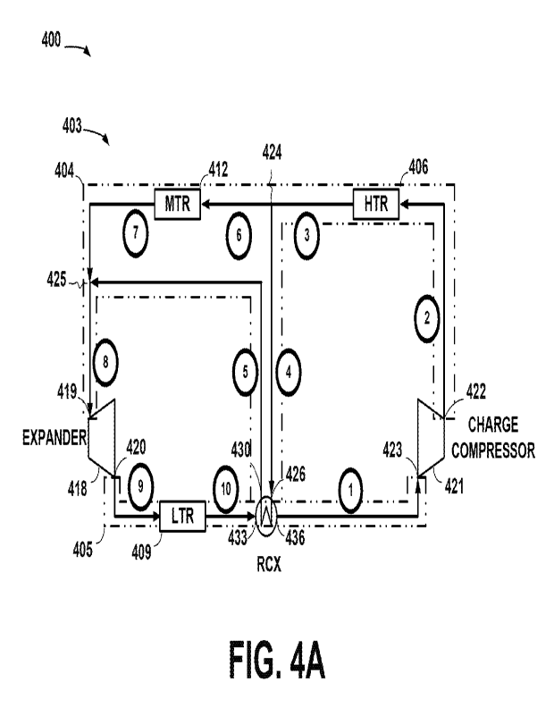
[013] FIG. 4A is a process flow diagram for a PTES system during a charging
phase of
a PTES operational cycle in accordance with one or more embodiments.
4
CA 03201373 2023- 6-6
WO 2022/125816
PCT/US2021/062675
[014] FIG. 4B is a process flow diagram for a PTES system during a generating
phase
of a PTES operational cycle in accordance with one or more embodiments.
[015] FIG. 5 illustrates one particular example of a control system by which
the working
fluid circuit of FIG. 4A-FIG. 4B may be configured for the charging phase,
shown in FIG.
4A, and the generating phase, shown in FIG. 4B.
[016] FIG. 6A-FIG. 6F illustrate several implementations of the thermal
reservoirs of FIG.
4A-FIG. 4B as may be found in various embodiments.
DETAILED DESCRIPTION
[017] One metric of overall cycle performance is the "round-trip efficiency"
(RTE"). This
parameter defines the amount of electrical energy (kWh) that can be produced
during the
generating phase divided by the amount of electrical energy that was consumed
during
the charging phase. The other key performance parameter is system capital
cost, which
can be defined in terms of generating capacity or in terms of storage
capacity.
[018] FIG. 1A and FIG. 1B illustrate a prior art PTES system 100 with a PTES
operating
cycle whose pressure-enthalpy diagram is shown in FIG. 2. Working fluid states
indicated
in FIG. 2 in boxes are indicated in FIG. 1A-FIG. 1B in circles. Thus, the
operating states
at various points in the operational cycle of the PTES system 100 can be
mapped from
the pressure-enthalpy diagram of FIG. 2 to the process flow diagrams of FIG.
1A-FIG.
1B. FIG. 1A illustrates a charging phase of the operating cycle while FIG. 1B
illustrates a
generating phase of the operating cycle. In the following discussions and the
accompanying drawings, the nomenclature set forth in Table 1 shall be used.
Table 1. Nomenclature
Acronym Meaning
ACC Air-cooled cooler
HTR High-temperature reservoir
HTX High-temperature reservoir to CO2 heat
exchanger
[PT Low-pressure turbine
LTR Low-temperature reservoir
CA 03201373 2023- 6-6
WO 2022/125816
PCT/US2021/062675
[TX Low-temperature reservoir to CO2 heat
exchanger
MTR Medium-temperature reservoir
MTX Medium-temperature reservoir to CO2 heat
exchanger
PFD Process flow diagram
PIES Pumped thermal energy storage
RCX Recuperator heat exchanger
RTE Round-trip efficiency
[019] The PTES system 100 includes a working fluid circuit 103, a HTR 106, a
LTR 109
and a recuperator RCX. The configuration of the working fluid circuit 103
depends, in part,
on whether the PIES system 100 is in the charging phase or the generating
phase of the
operational cycle. As those in the art having the benefit of this disclosure
will appreciate,
the configuration is generally a function of programmed control of fluid flow
valves. Thus,
in the charging phase some components of the working fluid circuit 103 are
switched in
and some are switched out by controlling the flow of the working fluid through
the working
fluid circuit 103. Similarly, in the generating phase, other components may be
switched in
and other components out, again by controlling the flow of the working fluid
through the
working fluid circuit 103. The fluid flow valves and controller(s) therefore
are omitted in
FIG. 1A-FIG. 1B for the sake of clarity.
[020] In the charging phase, as shown in FIG. 1A, the working fluid circuit
103 includes
an expander 115, a charge compressor 112, and an air-cooled cooler ACC1
between the
recuperator RCX and the expander 115. The expander 115 is used for expansion
processes in which the working fluid is expanded. The charge compressor 112 is
used
for compression processes in which the working fluid is compressed. In the
generating
phase, shown in FIG. 1B, the working fluid circuit 103 includes a pump 118 for
compression processes, Similarly, the working fluid circuit 103 includes a
power turbine
121 in the generating phase. Furthermore, the working fluid circuit 103 omits
the air-
cooled cooler ACC1 from the charging phase and in the generating phase
includes an
air-cooled cooler ACC2. The air-cooled cooler ACC2 is positioned between the
LTR 109
and the recuperator RCX.
[021] In the presently used nomenclature, "high-temperature" and "low-
temperature" are
relative to one another¨that is, the HTR operates at temperatures higher than
the
6
CA 03201373 2023- 6-6
WO 2022/125816
PCT/US2021/062675
temperatures at which the LTR operates. The terms "hot" and "cold" are used
relative to
one another. For instance, the HTR 106 may operate at temperatures ranging
from 100
to 340 C and the LTR 109 may operate at temperatures ranging from -2 to 2 C
depending
on the embodiment.
[022] In the charging phase, shown in FIG. 1A, heat transfers from the LTR 109
to the
working fluid and heat transfers from the working fluid to the HTR 106,
respectively. In
the generating phase, shown in FIG. 1B, heat transfer occurs in the opposite
direction.
Heat transfers from the working fluid to the LTR 109 and heat transfers to the
working
fluid from the HTR 106, respectively.
[023] Unlike a traditional heat engine, in a theoretical ideal cycle with 100%
efficient
turbornachinery, no pressure losses, and perfectly matched temperatures
through the
heat exchangers, the RTE of the PTES process is 100%. In practice,
thermodynamic
irreversibilities, pressure losses and finite temperature approaches through
the heat
exchangers result in lower RTE values. For the charging phase of the baseline
cycle
depicted in FIG. 1A, using carbon dioxide ("002") and a reasonable set of
efficiency
values, etc., one can calculate an RTE of 50-55%.
[024] Thermodynamic irreversibilities, for example, can introduce
inefficiency.
Thermodynamically ideal compression and expansion processes are described as
"adiabatic, isentropic" devices. In FIG. 2, the expansion and compression
processes are
represented by the diagonal lines¨for example, from State 4 to 5 in the
generating phase.
The term "isentropie refers to a constant entropy process. In the non-ideal
case shown,
the compression process is non-isentropic, thus showing a shallower slope when
increasing pressure than does the corresponding generation expansion process.
Due to
these irreversibilities, the compression process consumes more work than the
expansion
process returns.
[025] Inefficiency is also incurred in circulating the working fluid. The
pressure losses
during the heat addition and rejection processes (e.g., State 7 to State 1 in
the generating
process) represent work lost in circulating fluid through the heat exchangers
and piping.
Thus, the basic act of circulating the working fluid itself causes
inefficiencies.
7
CA 03201373 2023- 6-6
WO 2022/125816
PCT/US2021/062675
[026] Furthermore, finite temperature differences between the working fluid
and the
thermal storage media are required to drive heat transfer between the two
materials.
Because the direction of heat transfer reverses between the charging phase and
the
generating phase, and because the reservoir material temperatures are fixed,
the working
fluid temperatures during charging need to be higher than the HTR and lower
than the
HTR, while during generating they need to be lower than the HTR and higher
than the
HTR. These temperature differentials represent lost thermodynamic potential,
which
reduce the round-trip efficiency of the system.
[027] Still further, the PTES system 100 utilizes internal heat transfer, also
known as
"recuperation". This process is represented in the PTES system 100 by the
recuperator
RCX. Recuperation is used to elevate the temperature of the working fluid
entering the
compressor 112 during the charge cycle while also lowering the temperature of
the
working fluid entering the power turbine 115. Conversely, during the
generation cycle, the
PTES system 100 uses recuperation to preheat the working fluid before entering
the HTR
106 by extracting residual heat from the turbine 121 exhaust.
[028] The heat transfer between the working fluid and the LTR 109 and the
working fluid
and the HTR 106 occurs through a heat exchanger of the respective thermal
reservoir.
The heat exchanger is not shown for the sake of clarity. The heat transfer
process through
a heat exchanger can be illustrated in a temperature-heat transferred plot,
also known as
a "TO plot".
[029] FIG. 3 is a temperature-heat transferred ("TO") plot for the baseline
PTES cycle of
FIG. 2 in the PIES system 100 of FIG. 1A-FIG. 1B. The TO plot of FIG. 3 shows
how the
fluid temperature decreases/increases as heat is transferred when the working
fluid
pressure is high (curve 402) and when the working fluid pressure is low (curve
404). The
slope of the TO curves can be shown to be proportional to the inverse of the
product of
the fluid mass flow rate and specific heat capacity. The working fluid for the
PTES system
100 in FIG. 1A-FIG. 1B is CO2.
[030] In the baseline version of the cycle, the working fluid flow rate
through both sides
of the recuperator RCX is the same. In the thermodynamically ideal case, the
specific
heat capacity of the working fluid would be the same on both sides of the
recuperator
8
CA 03201373 2023- 6-6
WO 2022/125816
PCT/US2021/062675
RCX. In that situation, the two TO curves 402, 404 would be parallel. As the
heat
exchanger conductance ("UA") increased, the two curves would approach each
other,
and at the limit of infinite UA, would overlay each other.
[031] However, some working fluids, including CO2, have specific heat capacity
properties that vary with pressure as well as temperature. Since the two sides
of the heat
exchanger are at different pressures, the TO curves are no longer parallel,
but exhibit a
"pinch" behavior at one of the heat exchanger "ends". Even though the amount
of heat
lost by the hot stream is the same as the amount gained by the cold stream,
the
temperature of the hot stream exiting the heat exchanger is higher than the
temperature
of hot stream entering. This temperature differential represents a lost
"thermodynamic
potential value" and reduces system performance (a more rigorous analysis can
be
performed using thermodynamic exergy destruction calculation methods to arrive
at the
same conclusion). In this case, the excess temperature of the fluid leaving
the high-
pressure end of the recuperator requires external heat rejection to the
environment to
achieve a nearly fully liquid state at the expander outlet. This heat lost has
a direct impact
on cycle performance.
[032] As mentioned above, the presently disclosed technique reduces the impact
of
specific heat capacity mismatch across the recuperator to avoid the lost
exergy
associated with the TO slope mismatch and thereby improve cycle performance
markedly. In order to match the TQ curve slopes, the mass flow rate of the
high-heat
capacity fluid is reduced such that the product ("mcp") of the mass ("m") and
the specific
heat capacity ("cp") is the same on both sides of the recuperator. In the
supercritical
carbon dioxide ("sCO2") power cycle known as the re-compression Brayton cycle
("RCB
cycle"), this is accomplished by intentionally bypassing part of the CO2 flow
around the
high-pressure side of the low-temperature recuperator using a second "bypass"
compressor. However, because the PTES cycle operates at considerably lower
temperatures than does the RCB cycle, this option is not available as it would
require
compression from a two-phase flow inlet.
[033] Instead, during the charging phase, the presently disclosed technique
adds a flow
path parallel to the high-pressure side of the recuperator. Approximately 40%
of the high-
9
CA 03201373 2023- 6-6
WO 2022/125816
PCT/US2021/062675
pressure CO2 flow bypasses the high-pressure side of the recuperator and
transfers its
heat to a third heat transfer medium (the "medium-temperature reservoir", or
"MTR"). The
remaining approximately 60% of the flow proceeds through the recuperator. Now,
the
product of the mass and the specific heat capacity of both sides of the
recuperator is
nearly identical, thus permitting a much closer approach temperature between
the fluids.
The two flows are then recombined prior to passing through the expander. The
heat
extracted from the first 40% of the high-pressure CO2 is transferred to a
thermal storage
medium.
[034] During the generation cycle, the process is reversed. Approximately 60%
of the
CO2 flow is split from the pump discharge and its temperature increased by
transferring
heat from the MTR medium. The remainder of the CO2 passes through the high-
pressure
side of the recuperator, transferring heat from the recuperator. The flows
recombine prior
to being further heated by the high-temperature reservoir material.
[035] The reduced exergy destruction results in substantial improvement in
system
performance. With comparable high-temperature and low-temperature reservoirs
and
other pressure, temperature and heat exchanger area constraints, the new cycle
results
in eight points higher round-trip efficiency ("RTE"), increasing from
approximately 52% to
60%. It also enables the elimination of the charging phase ACC.
[036] Turning again to the drawings, FIG. 4A-FIG. 4B illustrate a charging
phase and a
generating phase, respectively, of an operational cycle for a PTES system 400
in
accordance with one or more embodiments of the presently disclosed technique.
Referring collectively to FIG. 4A and FIG. 4B, the PIES system 400 includes a
configurable working fluid circuit 403, a high-temperature reservoir ("HTR")
406, a low-
temperature reservoir ("LTR") 409, and a medium-temperature reservoir ("MTR")
412.
The PTES system 400 may be characterized as a "three reservoir system" because
there
are three reservoirs¨the HTR 406, the LTR 409, and the MTR 412.
[037] The HTR 406 is so called because it operates at temperatures higher than
those
at which the LTR 409 and the MTR 412 operate. Similarly, the LTR 409 operates
at
temperatures lower than those at which the HTR 406 and the MTR 412 operate.
The MTR
412 operates at temperatures intermediate those at which the HTR 406 and the
LTR 409
CA 03201373 2023- 6-6
WO 2022/125816
PCT/US2021/062675
operate. Thus, relative to the reservoirs HTR 406, LTR 409, and MTR 412, the
terms
"high", "medium", and "low" describe the relative temperatures at which the
three
reservoirs HTR 406, LTR 409, and MTR 412 operate.
[038] Each of the thermal reservoirs HTR 406, LTR 409, and MTR 412 include a
thermal
storage medium not separately shown. In the illustrated embodiment, the
thermal storage
media are sand, liquid water and a water/ice mixture for the HTR 406, MTR 412,
and LTR
409, respectively. However, the thermal storage medium may be any suitable
thermal
storage medium and alternative embodiments may use alternative thermal storage
media. Each of the thermal reservoirs HTR 406, MTR 412, and LTR 409 may
include heat
exchangers, piping, pumps, valves and other controls not separately shown to
transfer
heat between the thermal storage media and the working fluid during operation
of the
PTES system 400.
[039] For example, in the illustrated embodiment of FIG. 4A-FIG. 4B, the HTR
406 may
be what is known as a three-tank system such as the three-tank system 600
shown in
FIG. 6A. In a 3-tank system, during the charging process, the working fluid
enters a first
heat exchanger HTX1, where it transfers heat to a thermal reservoir medium. It
then
enters a second heat exchanger HTX2, where it transfers additional heat to a
second
thermal reservoir material. The thermal reservoir medium is transported from a
first tank
HTRc to the second heat exchanger HTX2, where it receives heat from the
working fluid.
Additional thermal reservoir material is stored in a second tank HTRm at an
intermediate
temperature is mixed with the thermal reservoir material. The mixed thermal
reservoir
material is then transported to the first heat exchanger HTX1, where it
receives heat from
the working fluid and is then stored in a third tank HTRh.
[040] During the generating process, the directions of flow are reversed.
Working fluid
first enters a second heat exchanger HTX2, where it receives heat from a
thermal
reservoir medium. The working fluid then enters a first heat exchanger HTX1,
where it
receives additional heat from the thermal reservoir medium. Thermal reservoir
medium is
transported from a third tank HTRh to the first heat exchanger HTX1, where it
transfers
heat to the working fluid. The cooled thermal reservoir medium is then split
into a first
portion and a second portion. The first portion of thermal reservoir material
is stored in a
11
CA 03201373 2023- 6-6
WO 2022/125816
PCT/US2021/062675
second tank HTRm. The second portion of thermal reservoir material is
transported to the
second heat exchanger HTX2 where it transfers additional heat to the working
fluid. The
cooled second portion of thermal reservoir material is stored in a first tank
HTRc.
[041] Similarly, in the illustrated embodiment of FIG. 4A-FIG. 4B, the MTR 412
and the
LTR 409 may be implemented in a two-tank system such as the two-tank system
603
shown in FIG. 6B. In a two-tank thermal reservoir, during the charging
process, the
working fluid enters a heat exchanger and transfers heat to a thermal
reservoir medium,
which could be a liquid such as oil, water or molten salt, or a flowing
granular medium,
such as silica sand or sintered bauxite. The thermal reservoir medium is
transported from
a first tank HTRc to the heat exchanger where it receives heat from the
working fluid, and
then is stored in a second tank HTRh.
[042] During the generating process, the direction of fluid flow is reversed.
Working fluid
enters a heat exchanger and received heat from a thermal reservoir medium. The
thermal
reservoir medium is transported from a second tank HTRh to a heat exchanger,
where it
transfers heat to the working fluid. The cooled thermal transport medium is
then stored in
the first tank HTRc.
[043] Other types of tank systems may be used in alternative embodiments. One
such
tank system is a solid thermocline reservoir 606, shown in FIG. 60. In a
thermocline
thermal reservoir, during the charging process, working fluid enters a
relatively lower
temperature thermal storage medium. The thermal storage medium is generally a
solid-
phase material through which the working fluid may flow, either through pores
in the
thermal storage medium or through embedded tubes or pipes (not shown) within
the
thermal storage medium material. As the working fluid flows through the
thermal storage
medium, heat is transferred from the working fluid to the thermal storage
medium, raising
its temperature. The working fluid is cooled to a lower temperature and exits
the thermal
reservoir.
[044] During the generating process, the direction of working fluid flow is
reversed.
Relatively lower temperature working fluid enters the heated thermal storage
medium.
Heat is transferred from the thermal storage medium, lowering its temperature,
to the
12
CA 03201373 2023- 6-6
WO 2022/125816
PCT/US2021/062675
working fluid, raising its temperature. The heated working fluid then exits
the thermal
reservoir.
[045] Another alternative tank system is a thermocline 609 with a thermal
transfer fluid
("TTF") loop, shown in FIG. 6D. Alternatively, during the charging process,
the working
fluid can transfer heat in a heat exchanger to a fluid thermal transfer
medium, such as oil,
water or air. The thermal transfer medium can then transfer heat to a thermal
storage
medium by flowing through the thermal storage medium. The cooled thermal
transfer fluid
is then transported to the heat exchanger, where it is reheated by the working
fluid. During
the generating process, the directions of working fluid and thermal transfer
fluid are
reversed.
[046] There are also one-tank thermocline storage systems such as the one-tank
thermocline storage system 612 in FIG. 6E. In a one-tank thermocline
reservoir, during
the charging process working fluid enters a heat exchanger, where it transfers
heat to a
thermal transfer fluid. The heated thermal transfer fluid is transported to
the top of a tank,
where its lower fluid density results in thermal stratification with the
higher-temperature
fluid remaining in an upper layer. Colder thermal transfer fluid is withdrawn
from the
bottom of the tank and is transported to the heat exchanger.
[047] During the generating process, the directions of flow are reversed.
Relatively
higher temperature thermal transfer fluid is transported from the top of the
tank to the heat
exchanger, where it heats the working fluid. The cooled thermal transfer fluid
is
transported to the bottom of the tank, where it remains thermally-stratified
and separated
from the higher temperature thermal transfer fluid.
[048] Embedded heat transfer surface systems such as the system 615 shown in
FIG.
6F are also known. In an embedded heat transfer surface thermal reservoir,
working fluid
is transported through a series of tubes, pipes or other fluid channels that
are immersed
in a relatively uniform temperature thermal storage medium. In this example,
the thermal
storage medium can be water or another fluid that is near its freezing point,
and the
working fluid can be a liquid that is near its boiling point, or a
liquid/vapor mixture at its
boiling point temperature. During the heat transfer process, heat is
transferred from the
working fluid to the thermal storage medium, causing the working fluid to boil
at constant
13
CA 03201373 2023- 6-6
WO 2022/125816
PCT/US2021/062675
temperature, while the thermal storage medium freezes from a liquid to a
solid. The
working fluid exits the thermal reservoir as a vapor at or slightly in excess
of its boiling
point
[049] During the generating process, the direction of working fluid flow is
reversed. The
working fluid enters at a pressure such that the boiling point of the working
fluid is slightly
above the freezing point of the thermal storage medium. Heat is transferred
from the
working fluid to the thermal storage medium, condensing the working fluid to a
liquid state,
and melting the thermal storage medium to a liquid state.
[050] One or more of the tank systems shown in FIG. 6A-FIG. 6E may be used to
implement the HTR 406, MTR 412, and LTR 409 in various alternative embodiments
depending on implementation specific considerations. However, the list is
neither
exhaustive nor exclusive. Still other tank system designs may also be used.
[051] Referring again to FIG. 4A-FIG. 4B, also common to the configurable
working fluid
circuit 403 in the charging phase and the generating phase is a bypass 415.
The bypass
415 includes a MTR 412. As mentioned above and as will be discussed further
below, the
bypass 415 permits a portion of the working fluid to bypass the high-pressure
side of the
recuperator RCX.
[052] FIG. 4A particularly illustrates the charging phase of the PTES
operating cycle. In
the charging phase, the configurable working fluid circuit 403 includes an
expander 418
and a charge compressor 421. In the illustrated embodiment, the working fluid
is CO2.
Alternative embodiments may use alternative working fluids as are known to the
art. The
following discussion of the charging phase is to be considered in conjunction
with
operating conditions set forth in Table 2. Those in the art having the benefit
of this
disclosure will appreciate that the values set forth in Table 2 are, in part,
a function of the
fact that the working fluid is CO2. A different implementation of the working
fluid may yield
different values for the operating conditions in Table 2.
[053] Also, in the following discussion, the state of the working fluid at any
given point in
the working fluid circuit 403 during the charging phase in FIG. 4A is shown as
a numeral
in a circle. Thus, the first state, or state 1, is shown as the numeral 1 in a
circle in FIG.
4A. This can then be mapped back into Table 2 for a fuller characterization of
the state.
14
CA 03201373 2023- 6-6
WO 2022/125816
PCT/US2021/062675
Table 2. Charging Phase Operating Conditions
State Out In
(kJ/kg) (MPa) ( C) (kJ/kg/K)
(kg/sec)
1 RCXI Com pr 568.91 3.20 114.94 2.287
49.53
2 Compr HTR 791.45 30.00 362.60 2.326 49.53
3 HTR Split1 428.89 29.80 118.22
1.594 49.53
4 Splitl A RCXh 428.89 29.80 118.22 1.594
28.76
RCXh Mix1A 196.14 29.70 1.16 0.890 28.76
6 Splitl B MTR 428.89 29.80 118.22 1.594
20.77
7 MTR Mix1B 238.23 29.70 23.45 1.037 20.77
8 Mix1 Exp 213.79 29.70 10.57 0.953
49.53
9 Exp LTR 189.36 3.40 -4.34 0.961
49.53
LTR RCXI 433.75 3.30 -1.05 1.863 49.53
[054] The disclosure herein references the "high-pressure side" and the "low-
pressure
side" of the recuperator RCX, or the "RCXh" and the "RCXI", respectively. In
the charging
phase illustrated in FIG. 4A, the charge compressor 421 pressurizes the
working fluid and
provides the motive force for circulating the working fluid in the charging
phase. The
expander 418 expands, or depressurizes, the working fluid.
[055] The portion of the working fluid circuit 403 through which the working
fluid is
pressurized by the charge compressor 421 circulates may be referred to as the
"high-
pressure side" of the working fluid circuit 403. Similarly, the portion of the
working fluid
circuit 403 through which the working fluid expanded by the expander 418
circulates may
be referred to as the "low-pressure side" of the working fluid circuit 403.
Thus, the high-
pressure side 404 of the working fluid circuit 403 extends from the outlet 422
of the charge
compressor 421 to the inlet 419 of the expander 418. The low-pressure side 405
extends
from the outlet 420 of the expander 418 to the inlet 423 of the charge
compressor 421.
[056] The high-pressure side of the recuperator RCX is the side of the
recuperator RCX
that interfaces with the high-pressure side 404 of the working fluid circuit
403. In the
charging phase shown in FIG. 4A, that would be the side of the recuperator RCX
defined
by the ports 426, 430 by which the pressurized working fluid circulates
through the
CA 03201373 2023- 6-6
WO 2022/125816
PCT/US2021/062675
recuperator RCX. The low-pressure side of the recuperator RCX is the side that
interfaces
with the low-pressure side 405 of the working fluid circuit 403. The low-
pressure side of
the recuperator RCX is defined by the ports 433, 436 by which the expanded
working
fluid circulates through the recuperator RCX.
[057] During the charging phase, beginning at the recuperator RCX, the working
fluid
exits the recuperator RCX and enters charge compressor 421 in a first state,
or state 1,
at a first temperature Ti and a first pressure Pi. The charge compressor 421
compresses
the working fluid and increases the temperature and pressure of the working
fluid. The
working fluid then leaves the charge compressor 421 in a second state at a
second
temperature T2 and a second pressure P2, the second temperature and the second
pressure being greater than the first temperature Ti and the first pressure
Pi, respectively.
[058] The working fluid then enters the high-temperature reservoir HTR 406 in
the
second state at the second temperature T2 and the second pressure Pz. In the
HTR 406,
heat is transferred from the working fluid to the thermal storage medium in
the HTR 406.
The heat transfer process reduces the pressure and the temperature of the
working fluid
to a third state as the working fluid exits the HTR 406 at a third temperature
T3 and a third
pressure P3.
[059] The working fluid then reaches a point 424 in the working fluid circuit
403 and
splits. A first portion of the working fluid enters the bypass 415 and a
second portion
enters the line 427. The second portion enters the line 427 in a fourth state
at a fourth
temperature T4 and a fourth pressure P4. Reference to Table 2 shows that the
fourth state
is at the third temperature and the third pressure¨i.e., T4=T3 and P4=P3¨but
differs from
the third state prior to the split. The fourth state differs by having a lower
mass flow rate
than does the third state although the second portion is at the same
temperature and
pressure as the working fluid in the third state. The second portion then
enters the high-
pressure side of the recuperator RCX through the port 426 in the fourth state
at the fourth
temperature T4 and the fourth pressure P4.
[060] In the recuperator RCX, heat is exchanged between the second portion and
the
circulating working fluid on the low-pressure side of the recuperator. This
heat exchange
cools the second portion to a fifth state in which, as shown in Table 2, the
second portion
16
CA 03201373 2023- 6-6
WO 2022/125816
PCT/US2021/062675
is at a significantly lower fifth temperature T5 and a slightly lower fifth
pressure P5. The
second portion then exits the recuperator RCX on the high-pressure side of the
recuperator RCX through the port 430 in a sixth state at a fifth temperature
Ts and a fifth
pressure P5.
[061] While the second portion is circulating through recuperator RCX, the
first portion
enters the bypass 415 in a sixth state. Reference to Table 2 shows that the
sixth state
differs from the third state prior to the split. The sixth state differs by
having a lower mass
flow rate than does the third state although the second portion is at the same
temperature
and pressure as the working fluid in the fourth state. The first portion then
enters the MTR
412 in the sixth state at a sixth temperature T6 and a sixth pressure P6.
[062] In the MTR 412, heat is transferred between the medium-temperature
thermal
reservoir MTR 412 and the first portion of the working fluid. Recall that the
MTR 412
operates at temperatures greater than the LTR 409 and less than the high-
temperature
thermal reservoir HTR 406. The first portion then exits the medium-temperature
heat
reservoir MTR 412 in a seventh state at a seventh temperature T7 and at a
seventh
pressure P7.
[063] After the first portion exits the MTR 412 in the seventh state and the
second portion
exits the recuperator RCX in the fifth state, the first and second portions
combine at a
point 425. After combining, the working fluid is in an eighth state at an
eighth pressure P8
and an eighth temperature T8 as set forth in Table 2. The combination of the
first portion
and the second portion, or the "combined portion", then enters the expander
418 in the
eighth state at the eighth pressure P8 and the eighth temperature T8,
whereupon it is
expanded and cooled. The combined portion of the working fluid exits the
expander 418
in a ninth state at a ninth temperature T9 and a ninth pressure P9.
[064] The working fluid then enters the LTR 409 in the ninth state at the
ninth
temperature T9 and the ninth pressure P9. In the LTR 409, heat is transferred
from the
LTR 409 to the working fluid. Note that the LTR 409 operates at temperatures
lower than
the medium temperature thermal reservoir MTR 412 and the high-temperature
thermal
reservoir HTR 406 as indicated in Table 2. The working fluid leaves the LTR
409 in a
tenth state at a tenth temperature Tio and a tenth pressure Rio.
17
CA 03201373 2023- 6-6
WO 2022/125816
PCT/US2021/062675
[065] Upon exit from the LTR 409, the working fluid enters the recuperator RCX
in the
tenth state at the tenth temperature Tio and the tenth pressure Pio and exits
in the first
state at the first temperature Ti and the first pressure Pi. In the
recuperator RCX, heat is
transferred from the working fluid on the high-pressure side to the working
fluid on the
low-pressure side of the recuperator RCX. Table 2 confirms (1) the temperature
drop in
the working fluid on the high-pressure side 404 as it transitions from the
fourth state to
the fifth state and (2) the temperature rise in the working fluid on the low-
pressure side
405 as it transitions from the tenth state to the first state. The working
fluid then begins
again the circulation through the working fluid circuit 403 discussed
immediately above.
[066] Turning now to FIG. 4B, the configuration of the working fluid circuit
403 in the
generating phase of the PTES operational cycle is shown. The operating
conditions at
various points in the working fluid circuit 403 are listed in Table 3. As
discussed above,
the flow direction of the working fluid through the working fluid circuit 403
is reversed
relative to that in the charging phase of the operational cycle. Note that the
expander 419
and the charge compressor 421 in the charging phase configuration of FIG. 4A
have been
replaced by a pump 450 and a power turbine 453, respectively. As can be seen
from
comparing states 1 and 2 in Table 3 and states 9 and 10 in Table 3, the pump
450
pressurizes the working fluid and the power turbine 453 depressurizes the
working fluid.
[067] The high-pressure side 404 of the working fluid circuit 403 therefore
extends, in
this phase of the operational cycle, from the outlet 451 of the pump 450 to
the inlet 454
of the power turbine 453. The low-pressure side 405 extends from the outlet
455 of the
power turbine 453 to the inlet 452 of the pump 450. Note that the high-
pressure side 404
includes the bypass 415, the line 427, the point 425, and the point 424. The
high-pressure
side 404 of the recuperator RCX is once again defined by the ports 426, 430
and the low-
pressure side 405 of the recuperator RCX is once again defined by the ports
433, 436.
18
CA 03201373 2023- 6-6
WO 2022/125816
PCT/US2021/062675
Table 3. Generating Phase Operating Conditions
State Out In
(kJ/kg) (MPa) ( C) (kJ/kg/K)
(kg/sec)
1 LTX Pump 204.69 3.87 2.00 1.016
79.71
2 Pump Split1 234.60 29.23 21.52 1.027
79.71
3 Splitl A RCXI 234.60 29.23 21.52 1.027
27.12
4 RCXI Mixl A 413.93 29.13 109.95 1.558
27.12
Splitl B MTR 234.60 29.23 21.52 1.027
52.58
6 MTR Mix1B 358.20 29.13 83.04 1.408 52.58
7 Mixl HTR 377.17 29.13 92.12 1.460
79.71
8 HTR PT 747.69 28.93 327.50 2.262 79.71
9 PT RCXh 589.50 4.07 139.10 2.296
79.71
RCXh ACC 528.48 3.97 81.58 2.141 79.71
11 ACC LTX 454.38 3.92 20.00 1.912
79.71
[068] Beginning with the LTR 409, the working fluid exits the LTR 409 and
enters the
pump 450 in a first state at a first temperature Ti and a first pressure Pi.
The pump 450
provides the motive force for circulation in the generating phase. The working
fluid exits
the pump 450 in a second state at a second temperature T2 and a second
pressure Pz.
[069] The working fluid, upon exiting the pump 450 in the second state, splits
at the point
425 into a first portion and a second portion. Note that, in the charging
phase illustrated
in FIG. 4A, the two portions of the working fluid split at the point 424 and
combine at the
point 425. However, since the flow direction of the working fluid is reversed
in the
generating phase relative to the charging phase, the two portions split at the
point 425
and combine at the point 424.
[070] The second portion enters the line 428 after the split at the point 425.
The second
portion enters the line 428 in a third state at a third temperature T3 and a
third pressure
P3. Reference to Table 2 shows that the third state is at the second
temperature and the
second pressure-that is, the third temperature T3 and the third pressure are
the same
as the second temperature and the second pressure. The third state
nevertheless differs
from the second state by having a significantly lower mass flow rate than does
the second
state. The second portion then circulates through the recuperator RCX from the
high-
pressure side 404 thereof, entering through the port 430 and exiting through
the port 426.
The second portion enters the recuperator RCX in the third state at the third
temperature
19
CA 03201373 2023- 6-6
WO 2022/125816
PCT/US2021/062675
and the third pressure and exits in a fourth state at a fourth temperature and
a fourth
pressure.
[071] After splitting at the point 425, the first portion of the working fluid
enters the bypass
415 in a fifth state at a fifth temperature T5 and fifth pressure P5. The
first portion enters
the MTR 412 in the fifth state at the fifth temperature T5 and the fifth
pressure Ps. In the
MTR 412, heat is transferred MTR 412 from the medium temperature thermal
reservoir
MTR 412 to the first portion. The first portion then exits the MTR 412 in a
sixth state at a
sixth temperature 16 and at a sixth pressure Pa.
[072] The first portion in the sixth state and the second portion in the
fourth state, upon
leaving the MTR 412 and the recuperator RCX, respectively, combine at the
point 424.
Note again that, in the charging phase illustrated in FIG. 4A, the two
portions of the
working fluid split at the point 424 and combine at the point 425. However,
since the flow
direction of the working fluid is reversed in the generating phase relative to
the charging
phase, the two portions split at the point 425 and combine at the point 424.
The combined
portion of the working fluid after the point 424 is in a seventh state at a
seventh
temperature 17 and a seventh pressure P7.
[073] The combined portion then enters the high-temperature reservoir HTR 406
in the
seventh state at the seventh temperature T7 and the seventh pressure P7. In
the high-
temperature reservoir HTR 406, heat is transferred from the high-temperature
thermal
reservoir HTR 406 to the combined portion. The combined portion then exits the
high-
temperature reservoir HTR 406 in an eighth state at an eighth temperature Ts
and an
eighth pressure Pa.
[074] The combined portion of the working fluid then enters the power turbine
453 in the
ninth state at the eighth temperature 18 and the eighth pressure Pa. More
particularly, the
combined portion enters the power turbine 453 from the high-pressure side 404
of the
working fluid circuit 403 through the inlet 454. The power turbine 453 expands
the working
fluid, which cools and reduces the pressure of the combined portion. The
combined
portion then exits the power turbine 453 in a ninth state at a ninth
temperature 19 and a
CA 03201373 2023- 6-6
WO 2022/125816
PCT/US2021/062675
ninth pressure P9. More particularly, the combined portion exits the power
turbine to the
low-pressure side 405 of the working fluid circuit 403 through the outlet 455.
[075] The combined portion then circulates through the low-pressure side of
the
recuperator RCX via the ports 433, 436. In the recuperator RCX, heat is
exchanged
between the second portion of the working fluid entering the recuperator RCX
from the
high-pressure side thereof as described above and the combined portion
entering the
recuperator RCX from the low-pressure side thereof. The combined portion then
exits the
recuperator RCX in a tenth state at a tenth temperature Tio and a tenth
pressure Pi0. The
combined portion then enters the air-cooled cooler ACC in the tenth state at
the tenth
temperature Tio and the tenth pressure Pia. The air-cooled cooler ACC then
cools the
combined portion to an eleventh state at an eleventh temperature Tii and an
eleventh
pressure Pli.
[076] The combined portion then enters the LTR 409 in the eleventh state at
the eleventh
temperature Tii and the eleventh pressure Pi 1. In the LTR 409, heat is
transferred from
the LTR 409 from the combined portion to the LTR 409 of the LTR 409. The
combined
portion then leaves the LTR 409 in the first state at the first temperature
and the first
pressure to recirculate through the working fluid circuit 403 as just
discussed_
[077] As was mentioned above, the configuration of the working fluid circuit
403 between
the charging phase shown in FIG. 4 and the charging phase shown in FIG. 4B may
be
controlled by fluid flow valves. Although such control systems are readily
known to those
in the art, one such control system 500 is shown in FIG. 5 for the sake of
completeness.
The control system 500 may include a plurality of fluid flow valves 505 and a
controller
510 sending control signals over electrical lines 515.
[078] The controller 510 includes a processor-based resource 520 that may be,
for
example and without limitation, a microcontroller, a microprocessor, an
Application
Specific Integrated Circuit ("ASIC"), an Electrically Erasable Programmable
Read-Only
Memory ("EEPROM"), or the like. Depending on the implementation of the
processor-
based resource, the controller 510 may also include a memory 525 encoded with
instructions (not shown) executable by the processor-based resource 520 to
implement
21
CA 03201373 2023- 6-6
WO 2022/125816
PCT/US2021/062675
the functionality of the controller 510. Again, depending on the
implementation of the
processor-based resource 520, the memory 525 may be a part of the processor-
based
resource 520 or a stand-alone device. For example, the instructions may be
firmware
stored in the memory portion of a microprocessor or they may be a routine
stored in a
stand-alone read-only or random-access memory chip. Similarly, in some
implementations of the processor-based resource 520¨e.g., an ASIC¨the memory
535
may be omitted altogether.
[079] Referring now collectively to FIG. 4A-FIG. 4B and FIG. 5, a controller
such as the
controller 510 may be used to configure the working fluid circuit 403 between
the charging
phase as shown in FIG. 4A and generating phase shown in FIG. 4B. The
controller 510
may send control signals to the fluid flow valves 505 to control the working
fluid flow.
Thus, to configure the working fluid circuit 403 for the charging phase, the
controller 510
controls the fluid flow valves 505 to direct the working fluid to the charge
compressor 421
and the expander 418 while diverting the working fluid away from the power
turbine 453
and the pump 450. Conversely, to configure the working fluid circuit 403 for
the generating
phase, the controller 510 controls the fluid flow valves 505 to direct working
fluid to the
power turbine 453 and the pump 450 while diverting the working fluid away from
the
charge compressor 421 and the expander 418.
[080] Referring now, collectively, to FIG. 4A-FIG. 4B, the high-pressure side
404 of the
working fluid circuit 403 includes the bypass 415 in both the charging phase
and the
operational phase. Thus, the bypass 415, including the heat exchanger (not
shown) of
the MTR 412, is on the high-pressure side of the recuperator RCX in both
phases. The
working fluid splits before entering the recuperator RCX at the point 424 in
the charging
phase and at the point 425 in the generating phase. The first portion bypasses
the high-
pressure-side of the recuperator RCX through the bypass 415 while the second
side
enters the recuperator RCX. The first and second portions then combine after
the second
portion passes through the recuperator RCX at the point 425 in the charging
phase and
at the point 424 in the generating phase.
22
CA 03201373 2023- 6-6
WO 2022/125816
PCT/US2021/062675
[081] Splits and combinations in the high-pressure side 404 of the working
fluid circuit
402 occur at the points 424, 425 in the illustrated embodiment. However,
whether the
points 424, 425 are split points or combination points will depend on whether
the operating
cycle is in the charging phase or in the generating phase. In the charging
phase, the point
424 is a split point and in the generating phase it is the combination point.
Conversely,
the point 425 is the combination point in the charging phase and the splitting
point in the
generating phase. Note that alternative embodiments may have split and
combination
points in addition to or in lieu of those disclosed herein. This is
particularly true in the
pursuit of design goals unrelated to implementing the technique disclosed
herein.
[082] The objective is to balance the product of the mass and the specific
heat capacity
on the low-pressure side 405 of the recuperator RCX with the product of the
mass and
the specific heat capacity on the high-pressure side 404 of the recuperator
RCX. The
term "balanced" means that the product of the mass and specific heat capacity
on both
sides of the recuperator RCX are equal. However, this may be difficult to
achieve with
precision in practice for a variety of reasons. Thus, the two products are
"balanced" when
they are "about", "roughly", or "approximately" equal in the sense that they
are both within
some margin for error in which the operation of the overall system achieves
some desired
level of efficiency. The desired level of efficiency may be expressed as a
range of values
to accommodate these types of concerns.
[083] Similarly, the terms "about", "approximately", etc. relative to any
quantity in this
disclosure indicates that some deviation from the stated quantity may be
tolerated so long
as the actual quantity is within some margin for error in which the operation
of the overall
system achieves some desired level of efficiency. For example, in the
illustrated
embodiment, the first portion may be 40% and the second portion may be 60% of
the
total, combined working fluid as will be discussed in more detail below. In
any given
embodiment employing CO2 for the working fluid, a precise split in these
proportions may
be difficult to achieve. Hence, some deviation may be tolerated so long as the
proportions
are "about" or "approximately" 40% and 60%. The same is true of any other
quantity
discussed or disclosed herein.
23
CA 03201373 2023- 6-6
WO 2022/125816
PCT/US2021/062675
[084] Those in the art having the benefit of this disclosure will appreciate
that both the
mass flow rate and the specific heat capacity in any given embodiment will be
implementation-specific depending on factors such as, for example, the choice
for
implementing the working fluid. Other factors, such as the operational ranges
of pumps,
expanders, compressors, etc. may impact the operating conditions for various
portions of
the working fluid circuit. Thus, the various quantities for the parameters in
Table 2 and
Table 3 may differ in alternative embodiments employing different substances
for the
working fluid or that implement certain equipment differently.
[085] As noted above, the working fluid in the illustrated embodiment is 002.
When the
working fluid is split as previously described, the first portion is 40% of
the total working
fluid and the second portion is 60% of the total working fluid. This is true
in both the
charging phase and in the generating phase. In alternative embodiments using
different
working fluids or different mass flow rates this proportion may be changed to
maintain the
balance of the mass flow rate and the specific heat on both the high-pressure
side and
the low-pressure side of the recuperator.
[086] Accordingly, in a first embodiment, a method for operating a pumped
thermal
energy storage ("PTES") system, the method comprises: circulating a working
fluid
through a working fluid circuit, the working fluid having a mass flow rate and
a specific
heat capacity; and balancing a product of the mass and the specific heat
capacity of the
working fluid on a high-pressure side of a recuperator and a low side of the
recuperator
as the working fluid circulates through the working fluid circuit.
[087] In a second embodiment, the first embodiment balances the product of the
mass
and the specific heat capacity of the working fluid on the high-pressure side
of the
recuperator and the low side of the recuperator as the working fluid
circulates through the
working fluid circuit by: splitting the working fluid into a first portion and
a second portion
on the high-pressure side of the recuperator; bypassing the first portion
around the high-
pressure side of the recuperator; cooling the first portion during the bypass;
circulating
the second portion through a recuperator; and combining the cooled first
portion with the
second portion after the second portion exits the recuperator.
24
CA 03201373 2023- 6-6
WO 2022/125816
PCT/US2021/062675
[088] In a third embodiment, the second embodiment cools the first portion
during the
bypass by circulating the working fluid through the bypass; and transferring
heat between
the working fluid and a medium temperature thermal reservoir. The heat
transfer includes,
in a charging phase, transferring heat from a low-temperature thermal
reservoir to the
working fluid and transferring heat from the working fluid to a medium-
temperature
thermal reservoir and high-temperature thermal reservoir and, in a generating
phase,
transferring heat from a high-temperature thermal reservoir and a medium
temperature
thermal reservoir (hot) to the working fluid and transferring heat from the
working fluid to
a low-temperature thermal reservoir.
[089] In a fourth embodiment, the second embodiment may be implemented such
that
the first portion of the working fluid comprises 40% of the working fluid
portion and the
second portion comprises 60% of the working fluid portion.
[090] In a fifth embodiment, the first embodiment may be implemented such that
circulating the working fluid through the working fluid circuit includes
circulating carbon
dioxide (CO2), the first portion of the working fluid comprises 40% of the
working fluid
portion, and the second portion comprises 60% of the working fluid portion.
[091] In a sixth embodiment, the second embodiment may be implemented such
that
circulating the working fluid through the working fluid circuit includes
circulating carbon
dioxide (CO2).
[092] In a seventh embodiment, the first embodiment may be implemented such
that
balancing a product of the mass and the specific heat capacity of the working
fluid on the
high-pressure side of a recuperator and the low side of the recuperator
includes a
charging phase and a generating phase. The charging phase includes circulating
60% of
a working fluid comprised of carbon dioxide (CO2) through the high-pressure
side of a
recuperator and circulating 100% of a working fluid comprised of CO2 through
the low-
pressure side of the recuperator. The generating phase includes circulating
60% of a
working fluid comprised of CO2 through the high-pressure side of a recuperator
and
circulating 100% of a working fluid comprised of CO2 through the low-pressure
side of the
recuperator.
CA 03201373 2023- 6-6
WO 2022/125816
PCT/US2021/062675
[093] In an eighth embodiment, the first embodiment may be implemented such
that
balancing the product of the mass and the specific heat capacity of the
working fluid on
the high-pressure side of the recuperator and the low side of the recuperator
as the
working fluid circulates through the working fluid circuit includes reducing
the mass flow
rate on the high-pressure side of the recuperator.
[094] In a ninth embodiment, the first embodiment further comprises exchanging
heat
between the second portion of the working fluid on the high-pressure side of
the
recuperator and a combined portion of the working fluid on the low-pressure
side of the
recuperator.
[095] In a tenth embodiment, a pumped thermal energy storage ("PTES") system,
comprises a medium temperature thermal reservoir and a working fluid circuit.
The
working fluid circuit includes a recuperator having a high-pressure side and a
low-
pressure side, the product of the mass and the specific heat capacity of a
working fluid is
balanced on the high-pressure side and the low-pressure side when the working
fluid
circulates through the working fluid circuit.
[096] In an eleventh embodiment, the tenth embodiment may be implemented such
that
the working fluid is carbon dioxide (CO2).
[097] In a twelfth embodiment, the tenth embodiment may be implemented such
that the
working fluid circuit includes a bypass by which a first portion of the
working fluid bypasses
the high-pressure side of the recuperator while a second portion of the
working fluid
circulates through the high-pressure side of the recuperator.
[098] In a thirteenth embodiment, the eleventh embodiment may be implemented
such
that the bypass includes a heat transfer between the first portion and the
medium
temperature thermal reservoir. Furthermore, the working fluid circuit further
includes: a
split on the high-pressure side of the recuperator splitting the working fluid
into the first
portion and the second portion, the first portion being less than the second
portion, the
second portion circulating through the recuperator from the high-pressure side
of the
recuperator; and a combination point on the high-pressure side of the
recuperator where
26
CA 03201373 2023- 6-6
WO 2022/125816
PCT/US2021/062675
the first portion combines with the second portion upon the second portion
exiting the
recuperator.
[099] In a fourteenth embodiment, the eleventh embodiment may be implemented
such
that the first portion is 40% of the total working fluid and the second
portion is 60% of the
total working fluid.
[0100] In a fifteenth embodiment, the eleventh embodiment may be implemented
such
that the working fluid is carbon dioxide (CO2), the first portion is 40% of
the total working
fluid, and the second portion is 60% of the total working fluid.
[0101] In a sixteenth embodiment, the tenth embodiment may be implemented such
that,
in operation, heat is exchanged between the second portion of the working
fluid on the
high side of the recuperator and a combined portion of the working fluid on
the low-
pressure side of the recuperator.
[0102] In a seventeenth embodiment, a method for operating a pumped thermal
energy
storage ("PIES") system includes circulating a working fluid through a working
fluid
circuit; and reducing a mass flow rate of the working fluid on a high-pressure
side of a
recuperator to balance a product of the mass and the specific heat of the
working fluid on
the high-pressure side and a low-pressure side of the recuperator while
circulating the
working fluid. The reducing may include bypassing the high-pressure side of
the
recuperator with a first portion of the working fluid and circulating a second
portion of the
working fluid through the high-pressure side of the recuperator.
[0103] In an eighteenth embodiment, the seventeenth embodiment may be
implemented
such that bypassing the high-pressure side of the recuperator includes: upon
transferring
heat between the working fluid and a high-temperature reservoir in a charging
phase,
bypassing the high-pressure side of a recuperator with a first portion of the
working fluid
and transferring heat from the first portion to a medium-temperature reservoir
during the
bypass while a second portion circulates through the recuperator, the first
portion being
less than the second portion; and upon exiting a pump in a generating phase,
bypassing
the high-pressure side of the recuperator with a third portion of the working
fluid while
27
CA 03201373 2023- 6-6
WO 2022/125816
PCT/US2021/062675
transferring heat from the medium-temperature reservoir to the third portion
during the
bypass while circulating a fourth portion of the working fluid through the
recuperator.
[0104] In a nineteenth embodiment, the seventeenth embodiment may include
exchanging heat between the second portion of the working fluid on the high
side of the
recuperator and a combined portion of the working fluid on the low-pressure
side of the
recuperator.
[0105] In a twentieth embodiment, the seventeenth embodiment may be
implemented
such that reducing the mass flow rate of the working fluid on the high-
pressure side of the
recuperator to balance the product of the mass and the specific heat of the
working fluid
on the high-pressure side and the low-pressure side of the recuperator while
circulating
the working fluid further includes: splitting the working fluid into the first
portion and the
second portion on the high-pressure side of the recuperator, the first portion
being less
than the second portion; cooling the first portion during the bypass; and
combining the
cooled first portion with the second portion after the second portion exits
the recuperator.
[0106] In a twenty-first embodiment, the twentieth embodiment may be
implemented such
that cooling the first portion during the bypass includes transferring heat
between the
working fluid and a medium temperature thermal reservoir. Transferring the
heat may
further include: in a charging phase, transferring heat from the working fluid
to a medium
temperature thermal reservoir and, in a generating phase, transferring heat
from a
medium temperature thermal reservoir to the working fluid.
[0107] In a twenty-second embodiment, the seventeenth embodiment may be
implemented such that circulating the working fluid through the working fluid
circuit
includes circulating carbon dioxide (CO2).
[0108] In a twenty-third embodiment, the seventeenth embodiment may be
implemented
such that the first portion of the working fluid comprises 40% of the working
fluid portion
and the second portion comprises 60% of the working fluid portion.
[0109] In a twenty-fourth embodiment, the seventeenth embodiment may be
implemented
such that circulating the working fluid through the working fluid circuit
includes circulating
28
CA 03201373 2023- 6-6
WO 2022/125816
PCT/US2021/062675
carbon dioxide (CO2) and the first portion of the working fluid comprises 40%
of the
working fluid portion and the second portion comprises 60% of the working
fluid portion.
[0110] In a twenty-fifth embodiment, a pumped thermal energy storage ("PTES")
system,
comprises a low-temperature reservoir, a high-temperature reservoir, a medium-
temperature reservoir, and a working fluid circuit configurable for a charging
phase and a
generating phase of a PTES operating cycle and through which, in use, a
working fluid
circulates. The working fluid circuit may include a recuperator; when in the
charging
phase: an expander positioned between the recuperator and the low-temperature
reservoir; and a charge compressor positioned between recuperator and the high-
temperature heat reservoir; and when in the generating phase: a pump
positioned
between recuperator and the low-temperature heat reservoir; and a power
turbine
positioned between recuperator and the high-temperature heat reservoir; and a
bypass,
by which, in both the charging phase and the generating phase, a first portion
of the
working fluid bypasses the high-pressure side of the recuperator and flows
through the
medium-temperature thermal reservoir, the medium-temperature thermal reservoir
transferring heat between the working fluid and the medium-temperature thermal
reservoir, while a second portion of the working fluid circulates through the
recuperator.
[0111] In a twenty-sixth embodiment, the twenty-fifth embodiment may be
implemented
such that the working fluid is carbon dioxide (002).
[0112] In a twenty-seventh embodiment, the twenty-fifth embodiment may be
implemented such that the first portion is 40% of the total working fluid and
the second
portion is 60% of the total working fluid.
[0113] In a twenty-eighth embodiment, the twenty-fifth embodiment may be
implemented
such that the working fluid is carbon dioxide (002), the first portion is 40%
of the total
working fluid, and the second portion is 60% of the total working fluid.
[0114] In a twenty-ninth embodiment, a method for operating a pumped thermal
energy
storage ("PTES") system, the method comprises: circulating a high-heat
capacity working
fluid through a working fluid circuit including a recuperator; and reducing a
mass flow rate
29
CA 03201373 2023- 6-6
WO 2022/125816
PCT/US2021/062675
of the working fluid on the high-pressure side of the recuperator such that
the product of
mass and the specific heat capacity is the same on both sides of a
recuperator. Reducing
the mass flow rate may include, in a charging phase: bypassing a recuperator
with a first
portion of the working fluid and transferring heat from the first portion to a
medium-
temperature reservoir during the bypass while circulating a second portion of
the working
fluid through the recuperator, the first portion being a lesser portion of the
working fluid
than the second portion; circulating a second portion through the recuperator
while the
first portion bypasses the recuperator and transferring heat from the second
portion while
circulating through the recuperator; and circulating both the first portion
and the second
portion together through an expander after the first portion bypasses the
recuperator and
the second portion circulates through the recuperator. Reducing the mass flow
rate may
include, in a generating phase: bypassing the recuperator with a third portion
of the
working fluid and transferring heat from the third portion to a medium-
temperature
reservoir during the bypass while circulating a fourth portion of the working
fluid through
the recuperator, the third portion being a greater portion than the fourth
portion; circulating
a fourth portion through the recuperator while the third portion bypasses the
recuperator
and transferring heat to the fourth portion while circulating through the
recuperator; and
circulating both the third portion and the fourth portion together through a
high-
temperature reservoir after the third portion bypasses the recuperator and the
fourth
portion circulates through the recuperator.
[0115] In a thirtieth embodiment, the twenty-ninth embodiment may be
implemented such
that the working fluid is carbon dioxide (CO2).
[0116] In a thirty-first embodiment, the thirtieth embodiment may be
implemented such
that the first portion represents approximately 40%, the second portion
represents
approximately 60% of the mass flow rate of the working fluid in the charging
phase, and
the third portion represents approximately 40% and the fourth portion
represents
approximately 60% of the mass flow rate of the working fluid in the generating
phase.
[0117] In a thirty-second embodiment, the twenty-ninth embodiment may be
implemented
such that the first portion represents approximately 40% and the second
portion
CA 03201373 2023- 6-6
WO 2022/125816
PCT/US2021/062675
represents approximately 60% of the mass flow rate of the working fluid in the
charging
phase and the third portion represents approximately 40% and the fourth
portion
represents approximately 60% of the mass flow rate of the working fluid in the
generating
phase.
[0118] Those skilled in the art having the benefit of this disclosure may
appreciate still
other embodiments of the technique disclosed herein.
[0119] The foregoing has outlined features of several embodiments so that
those skilled
in the art may better understand the present disclosure. Those skilled in the
art should
appreciate that they may readily use the present disclosure as a basis for
designing or
modifying other processes and structures for carrying out the same purposes
and/or
achieving the same advantages of the embodiments introduced herein. Those
skilled in
the art should also realize that such equivalent constructions do not depart
from the spirit
and scope of the present disclosure, and that they may make various changes,
substitutions and alterations herein without departing from the spirit and
scope of the
present disclosure.
31
CA 03201373 2023- 6-6