Note: Descriptions are shown in the official language in which they were submitted.
CA 03201623 2023-05-11
WO 2022/109517 PCT/US2021/072146
1
STRAP-FEEDING ASSEMBLY WITH STRAP-SIZE-ADJUSTMENT FEATURES
Priority Claim
[0001] This application claims priority to and the benefit of U.S.
Provisional Patent
Application No. 63/114,777, filed November 17, 2020, and U.S. Provisional
Patent Application
No. 63/166,666, filed March 26, 2021, the entire contents of both of which is
incorporated herein
by reference.
Field
[0002] The present disclosure relates to strapping machines, and more
particularly to
strapping machine strap-feeding assemblies with features that enable
adjustment of the strap-
feeding assemblies for use with different strap sizes.
Background
[0003] A strapping machine forms a tensioned loop of plastic strap
(such as
polyester or polypropylene strap) or metal strap (such as steel strap) around
a load. A typical
strapping machine includes a support surface that supports the load, a strap
chute that
circumscribes the support surface, a strapping head that forms the strap loop,
a controller that
controls the strapping head to strap the load, and a frame that supports these
components. A
typical strapping head includes a strap-feeding assembly for feeding strap
from a strap supply
into and around the strap chute and for retracting the strap so it exits the
strap chute and moves
radially inwardly into contact with the load, a strap-tensioning assembly for
tensioning the strap
around the load, and a strap-sealing assembly for cutting the strap from the
strap supply and
attaching two areas of the strap together to form the strap loop. Each of
these assemblies includes
a guide that defines a strap channel that the strap passes through as it moves
through the
assembly. The strap channels and the strap chute together define a strap path
that the strap moves
through.
[0004] To strap the load, the strap-feeding assembly feeds strap
(leading strap end
first) from the strap supply through the strap-tensioning assembly, through
the strap-sealing
CA 03201623 2023-05-11
WO 2022/109517 PCT/US2021/072146
2
assembly, and into and around the strap chute until the leading strap end
returns to the strap-
sealing assembly. While the strap-sealing assembly holds the leading strap
end, the strap-feeding
assembly retracts the strap to pull the strap out of the strap chute and onto
and around the load.
The strap-tensioning assembly then tensions the strap to a designated strap
tension. The strap-
sealing assembly cuts the strap from the strap supply to form a trailing strap
end and attaches the
leading and trailing strap ends to one another, thereby forming a tensioned
strap loop around the
load.
[0005] Different applications require strap of different sizes. For
instance, strap that
is 8 millimeters wide and 0.3 millimeters thick may be used for light-duty
applications, while
strap that is 16 millimeters wide and 0.85 millimeters thick may be used for
heavy-duty
applications. Certain known strapping machines are configured so they can
operate with strap of
different widths and thicknesses. The strap-feeding assemblies (and in some
cases the strap-
tensioning and/or strap-sealing assemblies) of these strapping machines have
guide members that
define fixed-width and fixed-thickness strap channels that are sized to
accommodate the widest
and thickest strap used with those strapping machines. These fixed-width and
fixed-thickness
strap channels become problematic when smaller-width and/or thinner strap is
used. Specifically,
since there is more empty space in the strap channels when smaller-width
and/or thinner strap is
used, the strap tends to "wander" laterally and/or vertically in the strap
channel and can snag and
become stuck in the strap channel. This results in a strap mis-feed and
requires the strap-feeding
assembly to retract the strap and re-feed it, which results in unwanted
downtime. It could also
damage the leading end of the strap, leading to material waste or (if not
recognized) sub-optimal
welds.
Summary
[0006] Various embodiments of the present disclosure provide a
strapping machine
strap-feeding assembly with features that enable adjustment of the strap-
feeding assembly to
accommodate different strap sizes.
[0007] Various embodiments of the strap-feeding assembly comprise a
strap-
feeding-assembly frame, a strap-driving assembly supported by the strap-
feeding-assembly
frame and comprising a feed wheel and an actuator operably connected to the
feed wheel to drive
CA 03201623 2023-05-11
WO 2022/109517 PCT/US2021/072146
3
the feed wheel, and a strap-guiding assembly supported by the strap-feeding-
assembly frame.
The strap-guiding assembly comprises a strap-guiding-assembly frame; a guide
member
mounted to the strap-guiding-assembly frame and at least partially defining a
strap channel
having an adjustable strap-channel width, the guide member movable relative to
the strap-
guiding-assembly frame frame between a first position corresponding to a first
strap-channel
width and a second position corresponding to a second strap-channel width
different from the
first strap-channel width; and a strap-channel-width adjuster operably
connected to the guide
member to move the guide member from its first position to its second
position.
[0008] Other embodiments of the strap-feeding assembly comprise a
strap-feeding-
assembly frame, a strap-driving assembly supported by the strap-feeding-
assembly frame and
comprising a feed wheel and an actuator operably connected to the feed wheel
to drive the feed
wheel, a first strap-guiding assembly supported by the strap-feeding-assembly
frame and
including one or more guide members partially defining a strap channel, and a
second strap-
guiding assembly supported by the strap-feeding-assembly frame. The second
strap-guiding
assembly comprises a housing; and a counter-roller assembly comprising: a
support mounted to
the housing; a counter roller mounted to the support and rotatable relative to
the support; and a
height adjuster operably connected to the counter roller to move the counter
roller from a first
position in which a first distance separates the counter roller and the feed
wheel to a second
position in which a second distance separates the counter roller and the feed
wheel, wherein the
second distance is greater than the first distance.
[0009] Other embodiments of the strap-feeding assembly comprise a
strap-feeding-
assembly frame comprising first and second strap-guiding-assembly mounts; and
a strap-guiding
assembly removably mountable to the strap-feeding-assembly frame and
comprising: a strap-
guiding-assembly frame defining a mounting opening sized to receive the first
strap-guiding-
assembly mount and comprising a strap-guiding-assembly retainer; and a guide
member
mounted to the strap-guiding-assembly frame and at least partially defining a
strap channel,
wherein the first and second strap-guiding-assembly mounts are positioned such
that the strap-
guiding assembly is mounted to the strap-feeding-assembly frame and in an
operational position
when: (1) the first strap-guiding-assembly mount is received in the mounting
opening of the
strap-guiding-assembly frame; and (2) the strap-guiding-assembly retainer
lockingly engages the
second strap-guiding-assembly mount.
CA 03201623 2023-05-11
WO 2022/109517 PCT/US2021/072146
4
Brief Description of the Figures
[0010] Figure 1 is a diagrammatic view of a strapping machine of the
present
disclosure.
[0011] Figure 2 is a perspective view of one example embodiment of a
strap-feeding
assembly of the strapping machine of Figure 1 with its upper strap-guiding
assembly in its closed
position.
[0012] Figure 3 is a perspective view of the strap-feeding assembly of
Figure 2 with
its upper strap-guiding assembly in its open position.
[0013] Figure 4 is another perspective view of the strap-feeding
assembly of Figure
2 with its upper strap-guiding assembly in its open position and with certain
components
removed for clarity.
[0014] Figures 5A and 5B are front and rear perspective views of the
strap-feeding-
assembly frame of the strap-feeding assembly of Figure 2.
[0015] Figures 6A and 6B are opposing perspective views of the strap-
feeding
assembly of Figure 2 with its covers removed to expose the strap-driving
assembly and with its
upper strap-guiding assembly in its closed position.
[0016] Figure 7A is a perspective view of the lower strap-guiding
assembly of the
strap-feeding assembly of Figure 2.
[0017] Figure 7B is an exploded perspective view of the lower strap-
guiding
assembly of Figure 7A.
[0018] Figure 7C is a perspective view of the strap-channel-width
adjuster of the
lower strap-guiding assembly of Figure 7A.
[0019] Figure 7D is a cross-sectional perspective view of the lower
strap-guiding
assembly of Figure 7A taken along line 7D-7D of Figure 7A and showing the
first and second
guide members in their first (narrow) configuration.
[0020] Figure 7E is a cross-sectional perspective view of the lower
strap-guiding
assembly of Figure 7A taken along line 7D-7D of Figure 7A and showing the
first and second
guide members in their second (wide) configuration.
[0021] Figure 7F is a cross-sectional side view of the lower strap-
guiding assembly
of Figure 7A taken along line 7F-7F of Figure 7A and showing the retainer.
CA 03201623 2023-05-11
WO 2022/109517 PCT/US2021/072146
[0022] Figure 8A is a perspective view showing the lower strap-guiding
assembly of
Figure 7A removed from the strap-feeding-assembly frame.
[0023] Figures 8B and 8C are perspective views showing the lower strap-
guiding
assembly of Figure 7A being mounted to the strap-feeding-assembly frame.
[0024] Figure 8D is a cross-sectional view of the lower strap-guiding
assembly of
Figure 7A mounted to the strap-feeding-assembly frame taken along line 8D-8D
of Figure 8C.
[0025] Figures 9A and 9B are perspective views of the upper strap-
guiding assembly
of the strap-feeding assembly of Figure 2 with certain components removed.
[0026] Figure 10 is an exploded perspective view of the counter-roller
assembly of
the upper strap-guiding assembly of Figure 9A.
[0027] Figures 11A and 11B are perspective views and Figure 11C is an
side view of
the height adjuster of the counter-roller assembly of Figure 10.
[0028] Figures 12A-12C are side views of part of the counter-roller
assembly
showing movement of the height adjuster from its locked position to its
unlocked position and
from its first rotational position to its second rotational position. More
specifically, Figures 12A
and 12C are cross-sectional side views taken along line 12A-12A of Figure 9A.
[0029] Figure 13A is a cross-sectional side view of part of the strap-
feeding
assembly of Figure 2 taken along line 13A-13A of Figure 9A and showing the
distance between
the counter roller of the counter-roller assembly and the feed wheel when the
height adjuster of
the counter-roller assembly is in its first rotational position.
[0030] Figure 13B is similar to Figure 13A but shows the distance
between the
counter roller of the counter-roller assembly and the feed wheel when the
height adjuster of the
counter-roller assembly is in its second rotational position.
[0031] Figure 13C is similar to Figure 13A but shows the distance
between the
counter roller of the counter-roller assembly and the feed wheel when the
height adjuster of the
counter-roller assembly is in its third rotational position.
[0032] Figures 14A and 14B are perspective views of one of the
eccentric mounting
pins of the upper strap-guiding assembly.
[0033] Figure 14C is an end-on view of the eccentric mounting pin of
Figures 14A
and 14B.
CA 03201623 2023-05-11
WO 2022/109517 PCT/US2021/072146
6
[0034] Figure 14D is a cross-sectional perspective view showing the
eccentric
mounting pin of Figures 14A and 14B.
Detailed Description
[0035] While the systems, devices, and methods described herein may be
embodied
in various forms, the drawings show and the specification describes certain
exemplary and non-
limiting embodiments. Not all of the components shown in the drawings and
described in the
specification may be required, and certain implementations may include
additional, different, or
fewer components. Variations in the arrangement and type of the components;
the shapes, sizes,
and materials of the components; and the manners of connections of the
components may be
made without departing from the spirit or scope of the claims. Unless
otherwise indicated, any
directions referred to in the specification reflect the orientations of the
components shown in the
corresponding drawings and do not limit the scope of the present disclosure.
Further, terms that
refer to mounting methods, such as mounted, connected, etc., are not intended
to be limited to
direct mounting methods but should be interpreted broadly to include indirect
and operably
mounted, connected, and like mounting methods. This specification is intended
to be taken as a
whole and interpreted in accordance with the principles of the present
disclosure and as
understood by one of ordinary skill in the art.
[0036] Figure 1 shows one embodiment of a strapping machine 1 of the
present
disclosure and components thereof in a simplified manner for clarity. The
strapping machine 1 is
configured to form a tensioned loop of strap around a load, and includes a
strapping-machine
frame (not shown), a strap chute CH, a load supporter LS, a strap-feeding
assembly 10, a strap-
tensioning assembly TM, a strap-sealing assembly SM, guides G1 and G2, and a
controller C
[0037] The strapping-machine frame is configured to support some (or
all) of the
other components of the strapping machine 1 and may be formed of any suitable
components
arranged in any suitable configuration. The load supporter LS is configured to
support loads¨
such as the palletized load L¨as they are strapped by and as they move through
the strapping
machine 1. The load supporter LS includes a support surface (not labeled) on
which loads are
positioned during strapping and over which loads move as they move through the
strapping
machine 1. In this example embodiment, the support surface includes multiple
rollers that
CA 03201623 2023-05-11
WO 2022/109517 PCT/US2021/072146
7
facilitate movement of the loads through the strapping machine 1. The rollers
may be driven or
undriven. In other embodiments, the support surface includes a driven conveyor
instead of
rollers.
[0038] The strap chute CH circumscribes the support surface of the
load supporter
LS and defines a strap path that the strap follows when fed through the strap
chute CH and from
which the strap is removed when retracted. The strap chute CH includes two
spaced-apart first
and second upstanding legs (not labeled), an upper connecting portion (not
labeled) that spans
the first and second legs, a lower connecting portion (not labeled) that spans
the first and second
legs and is positioned in the load supporter LS, and elbows (not labeled) that
connect these
portions. As is known in the art, the radially inward wall of the strap chute
CH is formed from
multiple overlapping gates that are spring biased to a closed position that
enables the strap to
traverse the strap path when fed through the strap chute CH. When the strap-
feeding assembly 10
exerts a pulling force on the strap to retract the strap, the pulling force
overcomes the biasing
force of the springs and causes the gates to pivot to an open position,
thereby releasing the strap
from the strap chute CH so the strap moves radially inward into contact with
the load L.
[0039] The strap-feeding assembly 10, the strap-tensioning assembly
TM, and the
strap-sealing assembly SM are together configured to form a tensioned strap
loop around the
load by feeding the strap through the strap chute CH, holding the leading
strap end while
retracting the strap to remove it from the strap chute CH so it contacts the
load L, tensioning the
strap around the load L to a designated tension, cutting the strap from the
strap supply to form a
trailing strap end, and connecting the leading strap end and the trailing
strap end to one another.
In this example embodiment, the strap-feeding assembly 10, the strap-
tensioning assembly TM,
and the strap-sealing assembly SM are distinct modules that are individually
attachable to and
removable from the strapping-machine frame. The guide G1 extends between the
strap-feeding
and strap-tensioning assemblies 10 and TM and is configured to guide the strap
as it moves
between those assemblies. Similarly, the guide G2 extends between the strap-
tensioning and
strap-sealing assembly TM and SM and is configured to guide the strap as it
moves between
those assemblies. In other embodiments, these assemblies form a strapping head
that is not
comprised of self-contained and individually removable modules.
[0040] Generally, the strap-feeding assembly 10 feeds strap from a
strap supply (not
shown) and into and around the strap chute CH and retracts the strap so it
exits the strap chute
CA 03201623 2023-05-11
WO 2022/109517 PCT/US2021/072146
8
CH and contacts the load L. The strap-feeding assembly 10 is described in more
detail below
with respect to Figures 2-14D.
[0041] The strap-tensioning assembly TM is configured to tension the
strap around
the load L. Briefly, the strap-tensioning assembly includes a tensioning wheel
driven by a tension
actuator. Once the strap-feeding assembly 10 retracts the strap so it contacts
the load L, the
tension actuator drives the tensioning wheel to tension the strap to a
designated (typically preset)
tension.
[0042] The strap-sealing assembly SM is configured to, after the strap-
tensioning
assembly TM tensions the strap to the designated tension, cut the strap from
the strap supply and
form the strap loop. The manner of attaching the leading and trailing strap
ends to one another
depends on the type of strapping machine and the type of strap. Certain
strapping machines
configured for plastic strap include a strap-sealing assembly with a friction
welder, a heated
blade, or an ultrasonic welder configured to attach the leading and trailing
strap ends to one
another. Some strapping machines configured for plastic strap or metal strap
include a strap-
sealing assembly with jaws that mechanically deform (referred to as "crimping"
in the industry)
or cut notches into (referred to as "notching" in the industry) a seal element
positioned around
the leading and trailing strap ends to attach them to one another. Other
strapping machines
configured for metal strap include a strap-sealing assembly with punches and
dies configured to
form a set of mechanically interlocking cuts in the leading and trailing strap
ends to attach them
to one another (referred to in the strapping industry as a "sealless"
attachment). Still other
strapping machines configured for metal strap include a strap-sealing assembly
with spot, inert-
gas, or other welders configured to weld the leading and trailing strap ends
to one another.
[0043] The controller C includes a processing device (or devices)
communicatively
connected to a memory device (or devices). For instance, the controller may be
a programmable
logic controller. The processing device may include any suitable processing
device such as, but
not limited to, a general-purpose processor, a special-purpose processor, a
digital-signal
processor, one or more microprocessors, one or more microprocessors in
association with a
digital-signal processor core, one or more application-specific integrated
circuits, one or more
field-programmable gate array circuits, one or more integrated circuits,
and/or a state machine.
The memory device may include any suitable memory device such as, but not
limited to, read-
only memory, random-access memory, one or more digital registers, cache
memory, one or more
CA 03201623 2023-05-11
WO 2022/109517 PCT/US2021/072146
9
semiconductor memory devices, magnetic media such as integrated hard disks
and/or removable
memory, magneto-optical media, and/or optical media. The memory device stores
instructions
executable by the processing device to control operation of the strapping
machine 1. In certain
embodiments, the strapping machine includes a single controller, while in
other embodiments the
strapping machine 1 has multiple controllers that operate together. In certain
embodiments, the
controller C is part of the strap-feeding assembly 10, the strap-tensioning
assembly TM, and/or
the strap-sealing assembly SM.
[0044] Returning to the strap-feeding assembly 10, the strap-feeding
assembly 10
feeds strap from a strap supply (not shown) and into and around the strap
chute CH and retracts
the strap so it exits the strap chute CH and contacts the load L. The strap-
feeding assembly 10
includes features that enable the strap-feeding assembly 10 to be adjusted to
accommodate
different strap sizes (e.g., different strap widths and thicknesses). Figures
2-14D show one
embodiment of the strap-feeding assembly 10 and components thereof The strap-
feeding
assembly 10 includes a strap-feeding-assembly frame 100, a strap-driving
assembly 200, a lower
(first) strap-guiding assembly 300, and an upper (second) strap-guiding
assembly 400.
[0045] The strap-feeding-assembly frame 100, which is best shown in
Figures 5A
and 5B, directly or indirectly supports the other components of the strap-
feeding assembly 10
and may be formed of any suitable components arranged in any suitable
configuration. In this
example embodiment, the strap-feeding-assembly frame 100 includes front
(first), back (second),
infeed side (third), and outfeed side (fourth) frame members 110, 120, 130,
and 140; first and
second support members 150 and 160; first-support-member mounting elements
152, 154, 156,
and 158; and second-support-member mounting elements 162, 164, 166, and 168.
[0046] The front and back frame members 110 and 120 are spaced-apart
from one
another, and the infeed side and outfeed side frame members 130 and 140 are
spaced-apart from
one another. The infeed side frame member 130 extends between one end of the
front frame
member 110 and one end of the back frame member 120, and the outfeed side
frame member
140 extends between the other end of the front frame member 110 and the other
end of the back
frame member 120. The first support member 150 extends between the front and
back frame
members 110 and 120 adjacent the infeed side frame member 130 and is mounted
to the front
and back frame members 110 and 120 via the first-support-member mounting
elements 152, 154,
156, and 158, which are pins in this example embodiment but may be any other
suitable
CA 03201623 2023-05-11
WO 2022/109517 PCT/US2021/072146
components (such as threaded fasteners). The second support member 160 extends
between the
front and back frame members 110 and 120 adjacent the outfeed side frame
member 140 and is
mounted to the front and back frame members 110 and 120 via the second-support-
member
mounting elements 162, 164, 166, and 168, which are pins in this example
embodiment but may
be any other suitable components (such as threaded fasteners).
[0047] Two covers 1000a and 1000b are removably attached to the strap-
feeding-
assembly frame 100 to at least partially enclose certain components of the
strap-driving assembly
200 and the lower strap-guiding assembly 300.
[0048] The strap-driving assembly 200, which is best shown in Figures
4, 6A, and
6B, engages the strap and, with the help of the upper strap-guiding assembly
400, feeds the strap
to and retracts the strap from the strap chute CH. The strap-driving assembly
200 includes a feed
wheel 210 having spaced-apart, circumferential strap-engaging surfaces 210a
and 210b (Figure
4), a driven gear 220, a drive gear 230, a drive belt 240, and an actuator
250. The feed wheel 210
and the driven gear 220 are both fixedly connected (such as via a keyed,
splined, or other
suitable connection) to a common drive shaft (not shown) that is, in turn,
mounted to the strap-
feeding-assembly frame 100 via one or more bearings (not shown). This enables
the drive shaft,
the feed wheel 210, and the driven gear 220 to rotate together relative to the
strap-feeding-
assembly frame 100 and the lower and upper strap-guiding assemblies 300 and
400. The actuator
250 (here an electric motor though any suitable actuator may be used) is
mounted to the strap-
feeding-assembly frame 100. The actuator 250 has an output shaft (not labeled)
to which the
drive gear 230 is fixedly mounted (such as via a keyed, splined, or other
suitable connection)
such that the output shaft and the drive gear 230 rotate together relative to
the strap-feeding-
assembly frame 100. The drive belt 240, which is a toothed belt in this
example embodiment,
operably connects the drive gear 230 and the driven gear 220. When the
actuator 250 rotates its
output shaft, the drive gear 230 rotates. The drive belt 240 transfers this
rotation to the driven
gear 220, which begins rotating and (via the drive shaft) causes the feed
wheel 210 to rotate.
Accordingly, the actuator 250 is operably connected to the feed wheel 210 (via
the drive gear
230, the drive belt 240, and the driven gear 220, or via any suitable
transmission components in
other embodiments) to rotate the feed wheel 210.
[0049] The lower strap-guiding assembly 300, which is best shown in
Figures 4 and
7A-7F, guides the strap through the strap-feeding assembly 10 (along with the
upper strap-
CA 03201623 2023-05-11
WO 2022/109517 PCT/US2021/072146
11
guiding assembly 400) and is adjustable to accommodate different strap widths.
As best shown
in Figure 7B, the lower strap-guiding assembly 300 includes: first and second
guide frame
members 310 and 320; first and second outer guide members 330 and 340; first,
second, third,
and fourth outer-guide-member directors 332, 334, 342, and 344; a center guide
member 350;
first and second strap-channel-width adjusters 360a and 360b; first second,
third, and fourth
spacers 370a, 370b, 370c, and 370d; first second, third, and fourth biasing
elements 380a, 380b,
380c, and 380d; multiple fasteners 390; multiple guide rollers 395; multiple
strap-channel-width-
adjuster retainers 398; and multiple lower-strap-guiding-assembly retainers
399.
[0050] The first guide frame member 310 includes a body 312 having a
first (infeed)
end 314 and a second (outfeed) end 316. A mounting opening 314a is defined in
the first (infeed)
end 314. The second (outfeed) end 316 includes a foot 316a that includes the
lower-strap-
guiding-assembly retainer 399a. The second guide frame member 320 includes a
body 322
having a first (infeed) end 324 and a second (outfeed) end 326. A mounting
opening 324a is
defined in the first (infeed) end 324. The second (outfeed) end 326 includes a
foot 326a that
includes the lower-strap-guiding-assembly retainer 399b. In other embodiments
(not shown), the
mounting openings are defined at the second (outfeed) ends of the first and
second guide frame
members, and the lower-strap-guiding-assembly retainers are included in the
first (infeed) ends
of the first and second guide frame members.
[0051] The lower-strap-guiding-assembly retainers 399a and 399b retain
the lower
strap-guiding assembly 300 on the strap-feeding-assembly frame 100, as
described below. In this
example embodiment, the lower-strap-guiding-assembly retainers include spring
plungers,
though they may be any other suitable components in other embodiments. Figure
7F shows the
lower-strap-guiding-assembly retainer 399a (the lower-strap-guiding-assembly
retainer 399b is
identical and is not separately shown or described for brevity). The lower-
strap-guiding-
assembly retainer 399a includes a body 399a1 threadably received in the foot
316a, a nose 399a2
captively received within a bore defined in the body 399a1, and a biasing
element 399a3 (here, a
compression spring) biasing the nose 399a2 toward the opening of the bore such
that part of the
nose 399a2 projects from the bore.
[0052] The first and second guide frame members 310 and 320 and the
center guide
member 350 (which is a plate in this example embodiment) are fixedly connected
to one another
by the spacers 370a-370d and the fasteners 390 to form a lower strap-guiding-
assembly frame.
CA 03201623 2023-05-11
WO 2022/109517
PCT/US2021/072146
12
Due to this fixed connection in this example embodiment, there is a first
fixed distance between
the first and second guide frame members 310 and 320, a second fixed distance
between the first
guide frame member 310 and the center guide member 350, and a third fixed
distance (which
here is the same as the second fixed distance) between the second guide frame
member 320 and
the center guide member 350. The first outer guide member 330 is slidably
mounted to the
spacers 370a-370d (which extend through corresponding openings in the first
outer guide
member 330) between the first guide frame member 310 and the center guide
member 350 such
that the first outer guide member 330 can move relative to the frame members
and the center
guide member between a first position adjacent the first guide frame member
310 (Figure 7E)
and a second position adjacent the center guide member 350 (Figure 7D).
Similarly, the second
outer guide member 340 is slidably mounted to the spacers 370a-370d (which
extend through
corresponding openings in the second outer guide member 340) between the
second guide frame
member 320 and the center guide member 350 such that the second outer guide
member 340 can
move relative to the frame members and the center guide member between a first
position
adjacent the second guide frame member 320 (Figure 7E) and a second position
adjacent the
center guide member 350 (Figure 7D).
[0053] As
best shown in Figure 7A, a first feed-wheel-receiving opening 300a is
formed between the first outer guide member 330 and the center guide member
350 and a second
feed-wheel-receiving opening 300b is formed between the second outer guide
member 340 and
the center guide member 350. Two of the guide rollers 395 are mounted to the
first outer guide
member 330 on the infeed and outfeed sides of the first feed-wheel-receiving
opening 300a and
extend partially into the strap channel SC. Similarly, two of the guide
rollers 395 are mounted to
the second outer guide member 340 on the infeed and outfeed sides of the
second feed-wheel-
receiving opening 300b and extend partially into the strap channel SC. In this
example
embodiment, the guide rollers 395 are rotatable relative to the outer guide
members 330 and 340,
while in other embodiments the guide rollers are not rotatable relative to the
outer guide
members 330 and 340. The strap engages the guide rollers as it moves through
the strap channel
SC, and the guide rollers help keep the strap in the lateral center of the
strap channel SC and
limits the strap's contact with the outer walls of the strap channel SC,
thereby reducing debris
formation and the potential for the strap to be damaged.
CA 03201623 2023-05-11
WO 2022/109517 PCT/US2021/072146
13
[0054] The first and second biasing elements 380a and 380b bias the
first outer guide
member 330 to its first position, and the third and fourth biasing elements
380c and 380d bias the
second outer guide member 340 to its first position. In this example
embodiment, the biasing
elements 380a-380d are compression springs. Also, in this example embodiment:
the first
biasing element 380a circumscribes the portion of the first spacer 370a
between the first guide
frame member 310 and the center guide member 350 and engages the first outer
guide member
330 and the center guide member 350, the second biasing element 380b
circumscribes the
portion of the fourth spacer 370d between the first guide frame member 310 and
the center guide
member 350 and engages the first outer guide member 330 and the center guide
member 350, the
third biasing element 380c circumscribes the portion of the first spacer 370a
between the second
guide frame member 320 and the center guide member 350 and engages the second
outer guide
member 340 and the center guide member 350, and the fourth biasing element
380d
circumscribes the portion of the fourth spacer 370d between the second guide
frame member 320
and the center guide member 350 and engages the second outer guide member 340
and the center
guide member 350.
[0055] The first and second strap-channel-width adjusters 360a and
360b control the
positions of the first and second outer guide members 330 and 340 and
therefore the width of the
strap channel partially defined by the lower strap-guiding assembly 300, as
described in detail
below. In this example embodiment, the first and second strap-channel-width
adjusters 360a and
360b are identical, so only the first strap-channel-width adjuster 360a is
shown and described in
detail. Turning to Figure 7C, the first strap-channel-width adjuster 360a
includes a head 362a, a
neck 364a, a body 366a, and a foot 368a. The head 362a is disc-shaped and has
a toothed or
knurled outer cylindrical surface to facilitate a user grasping and rotating
the first strap-channel-
width adjuster 360a (as described below). In other embodiments the head is
coated with or is
formed from a high-friction material, such as rubber. The neck 364a extends
from the head 362a
and, in this example embodiment, the head 362a is attached to the neck 364a
via a fastener (not
labeled). The neck 364a is cylindrical, and multiple aligned,
circumferentially spaced
depressions 364a1 are defined in the outer cylindrical surface of the neck
364a. The body 366a
extends from the neck 364a (and in this example embodiment is integrally
formed with the neck
364a). First and second spiral-shaped width-control grooves 366a1 and 366a2
are defined in the
outer cylindrical surface of the body 366a. The width-control grooves 366a1
and 366a2 are
CA 03201623 2023-05-11
WO 2022/109517
PCT/US2021/072146
14
mirror images of one another. For instance, if the width-control groove 366a1
is a right-hand
spiral, the width-control groove 366a2 is a left-hand spiral, and vice-versa.
The foot 368a is
cylindrical and extends from the body 366a (and in this example embodiment is
integrally
formed with the body 366a). The first strap-channel-width adjuster 360a
defines a rotational axis
A360a. The second strap-channel-width adjuster 360b has identical components
that are identified
below with element numbers in which a "b" replaces the "a" of the
corresponding element
numbers of the first strap-channel-width adjuster 360a.
[0056] The
first and second strap-channel-width adjusters 360a and 360b extend
through openings defined in the first and second guide frame members 310 and
320, the first and
second outer guide members 330 and 340, and the center guide member 350. The
first and
second strap-channel-width adjusters 360a and 360b are secured (such as via
set screws,
retaining clips or rings, or in any other suitable manner) such that they
cannot move relative to
these components parallel or transverse to their respective rotational axes
A360a and A36ob but can
rotate relative to these components about their respective rotational axes
A360a and A360b. The
first outer-guide-member director 332 has a threaded body 332a and a
projection 332b extending
from the body 332a. The body 332a of the first outer-guide-member director 332
is threadably
received in the first outer guide member 330 such that the projection 332b of
the first outer-
guide-member director is received in the width-control groove 366a1 of the
body 366a of the
first strap-channel-width adjuster 360a. The second outer-guide-member
director 334 has a
threaded body 334a and a projection 334b extending from the body 334a. The
body 334a of the
second outer-guide-member director 334 is threadably received in the first
outer guide member
330 such that the projection 334b of the second outer-guide-member director is
received in the
width-control groove 366b1 of the body 366b of the second strap-channel-width
adjuster 360b.
The third outer-guide-member director 342 has a threaded body 342a and a
projection 342b
extending from the body 342a. The body 342a of the third outer-guide-member
director 342 is
threadably received in the second outer guide member 340 such that the
projection 342b of the
third outer-guide-member director is received in the width-control groove
366a2 of the body
366a of the first strap-channel-width adjuster 360a. The fourth outer-guide-
member director 344
has a threaded body 344a and a projection 344b extending from the body 344a.
The body 344a of
the fourth outer-guide-member director 344 is threadably received in the
second outer guide
member 340 such that the projection 344b of the fourth outer-guide-member
director is received
CA 03201623 2023-05-11
WO 2022/109517 PCT/US2021/072146
in the width-control groove 366b2 of the body 366b of the second strap-channel-
width adjuster
360b.
[0057] As best shown in Figure 7A, the outer guide members 330 and 340
(along
with the upper strap-guiding assembly 400) define a strap channel SC
therebetween that has a
width W. When the first and second outer guide members 330 and 340 are in
their respective
second positions, referred to herein as a second (narrow) configuration, the
width of the strap
channel SC is a minimum width WAIN (Figure 7D). Conversely, when the first and
second outer
guide members are in their respective first positions, referred to herein as a
first (wide)
configuration, the width of the strap channel SC is a maximum width WMAX
(Figure 7E). The
width of the strap channel SC is adjustable between the minimum and maximum
widths WMIN
and WmAx via rotation of the first and second strap-channel-width adjusters
360a and 360b,
which enables the operator to tailor the width of the strap channel to conform
to strap of different
sizes. Put differently, the first and second strap-channel-width adjusters
360a and 360b are
operably connected to the first and second outer guide members 330 and 340 to
move the first
and second outer guide members between their respective first and second
positions to adjust the
width of the strap channel Sc.
[0058] Specifically, as explained above, the projections of the outer-
guide-member
directors are received in the spiral-shaped width-control grooves of the strap-
channel-width
adjusters. As the strap-channel-width adjusters are rotated, the projections
follow the grooves
and force the outer guide members to move toward or away from one another
(depending on the
direction of rotation). Figures 7D and 7E illustrate this for the second strap-
channel-width
adjuster 360b. In Figure 7D the first and second outer guide members 330 and
340 are in the
second (narrow) configuration (i.e., are in their respective second positions)
and the width of the
strap channel SC is WmIN. To move the first and second outer guide members 330
and 340 away
from one another and toward the first (wide) configuration, the operator
rotates the second strap-
channel-width adjuster 360b clockwise (from the perspective shown in Figures
7D and 7E).
Initially, the projections 334b and 344b of the second and fourth guide-place
directors 334 and
344¨which are respectively received in the first and second width-control
grooves 366b1 and
366b2 of the body 366b of the second strap-channel-width adjuster 366¨are
positioned at the
ends of the grooves nearest the longitudinal center of the body. As the second
strap-channel-
width adjuster 360b rotates, the walls that define the width-control grooves
force the projections
CA 03201623 2023-05-11
WO 2022/109517 PCT/US2021/072146
16
outward such that they follow the grooves and move toward the ends of the
grooves furthest
from the longitudinal center of the body. This in turn forces the first and
second outer guide
members 330 and 340 to move toward the first configuration, as shown in Figure
7E.
[0059] The strap-channel-width-adjuster retainers 398 engage the strap-
channel-
width adjusters 360a and 360b to help maintain the strap-channel-width
adjusters 360a and 360b
in their rotational positions by resisting rotation. In this example
embodiment, the strap-channel-
width-adjuster retainers 398 include spring plungers, though they may be any
other suitable
components in other embodiments. Figure 7F shows one strap-channel-width-
adjuster retainer
engaging the second strap-channel-width adjuster 360b (another identical strap-
channel-width-
adjuster retainer engages the first strap-channel width adjuster 360a and is
not shown for
brevity). The strap-channel-width-adjuster retainer 398 includes a body 398a
threadably received
in the first guide frame member 310, a nose 398b captively received within a
bore defined in the
body 398a, and a biasing element 398c (here, a compression spring) biasing the
nose 398b
toward the opening of the bore such that part of the nose 398b projects from
the bore. The strap-
channel-width-adjuster retainer 398 is positioned so the nose 398b is adjacent
to and received in
the depressions 364b1 in the neck 364a of the strap-channel-width adjuster
360. To rotate the
strap-channel-width adjuster, the force of the spring 398c must be overcome.
This prevents
unwanted rotation of the strap-channel-width adjuster.
[0060] As shown in Figures 8A-8D, the lower strap-guiding assembly 300
is
removably mounted to the strap-feeding-assembly frame 100 generally above the
strap-driving
assembly 200. Specifically, the lower strap-guiding assembly 300 is removably
mounted to first
(infeed) and second (outfeed) lower-strap-guiding-assembly mounts of the strap-
feeding-
assembly frame 100. In this example embodiment, the first lower-strap-guiding-
assembly mount
includes the first-support-member mounting elements 152 and 154, which are
accessible via
openings 150a and 150b defined through the first platform 150 (Figure 8A). The
second lower-
strap-guiding-assembly mount includes the second-support-member-mounting
elements 162 and
164, which are accessible via openings 160a and 160b defined through the
second platform 160
(Figure 8A).
[0061] To mount the lower strap-guiding assembly 300 to the strap-
feeding-
assembly frame 100, the lower portions of the first ends 314 and 324 of the
first and second
guide frame members 310 and 320 are inserted into the openings 150a and 150b
in the first
CA 03201623 2023-05-11
WO 2022/109517 PCT/US2021/072146
17
platform 150, respectively, and positioned so the first-support-member
mounting elements 152
and 154 (i.e., the first lower-strap-guiding-assembly mount in this example
embodiment) are
received in their respective mounting openings 314a and 324a, as shown in
Figure 8B. The lower
strap-guiding assembly 300 is then rotated about the first-support-member
mounting elements
152 and 154 and toward the second platform 160 until the: (1) undersides of
the second ends 316
and 326 of the first and second guide frame members 310 and 320 lockingly
engage the second-
support-member-mounting elements 162 and 164 (i.e., the second lower-strap-
guiding-assembly
mount in this example embodiment), respectively; and (2) the noses 399a2 and
399b2 of the
lower-strap-guiding-assembly retainers 399a and 399b engage the second-support-
member-
mounting elements 162 and 164, respectively, as shown in Figures 8C and 8D.
[0062] Once the lower strap-guiding assembly 300 is in this
operational position, the
lower-strap-guiding-assembly retainers 399a and 399b retain it in place. More
specifically, the
spring-biased noses 399a2 and 399b2 resist rotation of the strap-guiding
assembly 300 away
from its operational position. To remove the lower strap-guiding assembly 300
from the strap-
feeding assembly frame 100, the operator reverses the above sequence, making
sure to lift with
enough force to overcome the forces of the springs 399a3 and 399b3 of the
lower-strap-guiding-
assembly retainers 399a and 399b. The operator therefore does not need any
tools to remove the
lower strap-guiding assembly from the strap-feeding-assembly frame (at least
in this example
embodiment), making removal quick and easy.
[0063] In certain embodiments, the second strap-guiding-assembly mount
defines an
opening sized to receive part of the nose when the strap-guiding assembly is
in its operational
position.
[0064] As shown in Figure 4, the lower strap-guiding assembly 300
(when mounted
to the strap-feeding-assembly frame 100) is positioned such that the strap-
engaging surface 210a
of the feed wheel 210 extends into the first feed-wheel-receiving opening 300a
and the strap-
engaging surface 210b of the feed wheel 210 extends into the second feed-wheel-
receiving
opening 300b such that these surfaces can engage the strap (when the strap is
received in the
strap channel SC).
[0065] The upper strap-guiding assembly 400, which is best shown in
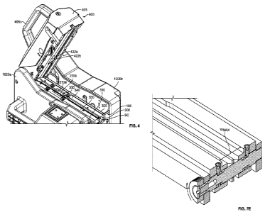
Figures 2-4
and 9A-14D, forces the strap against the feed wheel 210 of the strap-driving
assembly 200 and is
adjustable in two ways to accommodate different strap thicknesses. The upper
strap-guiding
CA 03201623 2023-05-11
WO 2022/109517 PCT/US2021/072146
18
assembly 400 includes a housing 405, a strap-channel cover 410, a counter-
roller assembly 420,
a counter-roller-assembly mounting pin 430, and a biasing assembly 440.
[0066] The upper strap-guiding assembly 400 is mounted to the strap-
feeding-
assembly frame 100 and pivotable relative to the strap-feeding-assembly frame
100, the strap-
driving assembly 200, and the lower strap-guiding assembly 300 about a pivot
(not shown)
between a closed position (Figure 2) and an open position (Figures 3 and 4). A
gas spring 60
(Figures 3 and 4) or other suitable component assists in pivoting the upper
strap-guiding
assembly 400 from its closed position to its open position and retains the
upper strap-guiding
assembly 400 in the open position (until it is forced back to the closed
position against the force
of the gas spring). When the upper strap-guiding assembly 400 is in its closed
position, a locking
pin 50 may be inserted through the upper strap-guiding assembly 400 and two
ears 105a and
105b of the strap-feeding-assembly frame 100 to lock the upper strap-guiding
assembly 400 in
place and prevent it from pivoting from its closed position to its open
position. The locking pin
50 must be removed (as shown in Figure 3) before the upper strap-guiding
assembly 400 can be
pivoted to its open position.
[0067] The housing 405 supports some (or all) of the other components
of the upper
strap-guiding assembly 400 and may be formed of any suitable component(s)
arranged in any
suitable configuration. In this example embodiment, the housing 405 includes a
handle 405b to
facilitate carrying the strap-feeding assembly 10.
[0068] The strap-channel cover 410 covers the lower strap-guiding
assembly 300
when the upper strap-guiding assembly 400 is in its closed position and, along
with the lower
strap-guiding assembly 300, forms the strap channel SC. The strap-channel
cover 410 includes a
base including first and second outer guide members 412a and 412b and a center
guide member
414 extending along the lateral center of the base between the first and
second outer guide
members. As best shown in Figure 9B, a first counter-roller-receiving opening
410a is formed
between the first outer guide member 412a and the divider 414 and a second
counter-roller-
receiving opening 410b is formed between the second outer guide member 412b
and the divider
414.
[0069] The strap-channel cover 410 is removably mounted to the housing
405 via
first and second eccentric mounting pins 470 and 480 (explained below with
respect to Figures
14A-14D). The eccentric mounting pins 470 and 480 are manipulatable (here,
rotatable) to
CA 03201623 2023-05-11
WO 2022/109517 PCT/US2021/072146
19
control the distance between the strap-channel cover 410 and the lower strap-
guiding assembly
300 and therefore control the height (not labeled) of the strap channel SC. In
this example
embodiment, the first and second eccentric mounting pins 470 and 480 are
identical, so only the
second eccentric mounting pin 480 is shown and described in detail. The second
eccentric
mounting pin 480 includes a head 482, a body 484, and a foot 486. The head 482
is cylindrical,
and multiple aligned, circumferentially spaced depressions 482a are defined in
the outer
cylindrical surface of the head 482. The body 484 is cylindrical and extends
from the head 482
(and in this example embodiment is integrally formed with the head 482). The
foot 486 is
cylindrical and extends from the body 484 (and in this example embodiment is
integrally formed
with the body 484). The head 482 and the foot 486 define a longitudinal axis
A482, and the body
484 defines a longitudinal axis A484 that, as best shown in Figure 14C, is
laterally offset from the
longitudinal axis A482. Put differently, the body 484 is eccentrically mounted
to the head 482 and
the foot 486. The first eccentric mounting pin 470 has identical components.
[0070] As shown in Figure 14D, the head 482 and the foot 486 of the
second
eccentric mounting pin 480 are received in openings (not labeled) in the
housing 405, and the
body 484 of the eccentric mounting pin 480 extends through openings (not
labeled) in the first
and second outer guide members 412a and 412b of the base of the strap-channel
cover 410. Due
to this mounting configuration, the second eccentric mounting pin 480 is
rotatable relative to the
housing 405 and the strap-channel cover 410 about the first longitudinal axis
A482. Since the
body 484 is eccentrically mounted to the head 482 and the foot 486, rotation
of the second
eccentric mounting pin 480 causes the body 484 to rotate around the first
longitudinal axis A482,
which causes the strap-channel cover 410 to further from or closer to the
lower strap-guiding
assembly 300, thereby increasing or decreasing the height of the strap channel
SC. Although not
labeled for clarity, a spring-biased retainer (similar to the strap-channel-
width-adjuster retainer
398 described above and shown in Figure 7F) engages the depressions 482a to
prevent unwanted
rotation of the eccentric mounting pin 480.
[0071] The counter-roller assembly 420, best shown in Figure 10,
includes a support
421, a counter roller 422, a counter-roller mounting pin 423, a height-
adjuster locking pin 424, a
height adjuster 425, a height-adjuster biasing element 426, a washer 427, and
a retaining ring
428. The support 421 includes a generally L-shaped body formed from a biasing-
assembly-
engagement arm 421a and two spaced-apart counter-roller-mounting arms 421b and
421c. A
CA 03201623 2023-05-11
WO 2022/109517 PCT/US2021/072146
height-adjuster-receiving bore 421d is defined through the support 421 at the
junction between
the arm 421a and the arms 421b and 421c. The counter roller 422, which
includes spaced-apart,
circumferential strap-engaging surfaces 422a and 422b, is mounted between the
counter-roller-
mounting arms 421b and 421c via the counter-roller mounting pin 423. The
counter roller 422 is
freely rotatable about the counter-roller mounting pin 423 relative to the
support 421. In this
example embodiment, the counter roller 422 includes a bearing (not labeled)
through which the
counter-roller mounting pin 423 extends. The height-adjuster locking pin 424
is fixedly attached
to and projects from the counter-roller-mounting arm 421b of the support 421
adjacent the
height-adjuster-receiving bore 421d.
[0072] The height adjuster 425, best shown in Figures 11A-11C,
includes a head
425a and a body 425b. The head 425a is disc-shaped and has an outer surface
425a1, an
opposing inner surface 425a2, and a cylindrical perimeter surface 425a3
between the outer and
inner surfaces. The perimeter surface 425a3 is toothed or knurled to
facilitate a user grasping and
rotating the height adjuster 425 (as described below). In other embodiments
the head is coated
with or is formed from a high-friction material, such as rubber. The neck 425b
extends from the
head 425a and, in this example embodiment, is integrally formed with the head
425a. The neck
425b is cylindrical, and a circumferential groove 425b1 is defined in the
outer cylindrical surface
of the neck 425b near its free end opposite the head 425a.
[0073] As shown in Figure 11C, the head 425a and the neck 425b share a
longitudinal axis A425ab. As shown in Figure 11B, a curved groove 425a4 is
defined in the inner
surface 425a2 of the head 425a. In this example embodiment, the groove 425a4
is radially
located (relative to the axis A425ab) between the perimeter surface 425a3 of
the head 425a and the
body 425b. And in this example embodiment, the groove 425a4 extends about 180
degrees. A
first locking-pin-receiving bore 425a5 is defined through the head 425a and
intersects the groove
425a4 at a first end of the groove 425a4, a third locking-pin-receiving bore
425a7 is defined
through the head 425a and intersects the groove 425a4 at a second end of the
groove 425a4, and
a second locking-pin-receiving bore 425a6 is defined through the head 425a and
intersects the
groove 425a4 about halfway between the first and third locking-pin-receiving
bores 425a5 and
425a7.
[0074] As best shown in Figure 11C, a mounting-pin-receiving bore 425c
is defined
through the head 425a and the neck 425b. The mounting-pin-receiving bore 425c
has a
CA 03201623 2023-05-11
WO 2022/109517 PCT/US2021/072146
21
longitudinal axis A425c that is parallel to and offset from (i.e., not coaxial
with) the axis A425ab.
The fact that these axes are offset (i.e., that the mounting-pin-receiving
bore 425c does not share
the same longitudinal axis as the head 425a and the neck 425b) enables the
height of the counter
roller 422 relative to the feed wheel 210 to be adjusted to accommodate for
strap of different
thicknesses, as described below.
[0075] As best shown in Figures 10 and 12B, the height adjuster 425 is
mounted to
the support 421. Specifically, the body 425b of the height adjuster 425 is
received in and extends
through the height-adjuster-receiving bore 421d of the support 421 such that
the free end of the
body 425b (opposite the head 425a) projects from the height-adjuster-receiving
bore 421d. The
height-adjuster biasing element 426 and the washer 427 circumscribe the
portion of the body
425b projecting from the height-adjuster-receiving bore 421d, and the
retaining ring 428 is
received in the groove 425b1. The height-adjuster biasing element 426 and the
washer 427 are
thus sandwiched between the body 421 and the retaining ring 428. The height
adjuster 425 is
rotationally positioned such that the height-adjuster locking pin 424 is
received in the groove
425a4.
[0076] The height adjuster 425 is movable relative to the support 421
and the height-
adjuster locking pin 424 in two ways. First, the height adjuster 425 is
longitudinally movable
relative to the support 421 and the height-adjuster locking pin 424 parallel
to the axis A425ab
between a locked position and an unlocked position. When the height adjuster
425 is in its
locked position (Figure 9A), the height-adjuster locking pin 424 is received
in one of the
locking-pin-receiving bores 425a5, 425a6, or 425a7, which prevents the height
adjuster 425 from
rotating. When the height adjuster 425 is in its unlocked position (Figure
12B), the height-
adjuster locking pin 424 is received in the groove 425a4 but removed from the
locking-pin-
receiving bores 425a5, 425a6, and 425a7, which enables the height adjuster 425
to rotate (as
permitted by the groove 425a4). The height-adjuster biasing element 426 biases
the height
adjuster 425 to its locked position. To move the height adjuster 425 from its
locked position to its
unlocked position, an operator must pull the height adjuster 425 with enough
force to overcome
the biasing force of the height-adjuster biasing element 426.
[0077] Second, the height adjuster 425 is¨when in its unlocked
position¨rotatable
relative to the support 421 and the height-adjuster locking pin 424 among a
first rotational
position that corresponds to the first locking-pin-receiving bore 424a5, a
second rotational
CA 03201623 2023-05-11
WO 2022/109517 PCT/US2021/072146
22
position that corresponds to the second locking-pin-receiving bore 424a6, and
a third rotational
position that corresponds to the third locking-pin-receiving bore 424a7.
Specifically, when the
height adjuster 425 is in its first rotational position, the height-adjuster
locking pin 424 is
received in (when the height adjuster 425 is in its locked position) the first
locking-pin-receiving
bore 425a5 or in front of (when the height adjuster 425 is in its unlocked
position) the first
locking-pin-receiving bore 425a5. When the height adjuster 425 is in its
second rotational
position, the height-adjuster locking pin 424 is received in (when the height
adjuster 425 is in its
locked position) the second locking-pin-receiving bore 425a6 or in front of
(when the height
adjuster 425 is in its unlocked position) the second locking-pin-receiving
bore 425a6. When the
height adjuster 425 is in its third rotational position, the height-adjuster
locking pin 424 is
received in (when the height adjuster 425 is in its locked position) the third
locking-pin-receiving
bore 425a7 or in front of (when the height adjuster 425 is in its unlocked
position) the third
locking-pin-receiving bore 425a7. As described below, the rotational position
of the height
adjuster 425 controls the height of the counter roller 422 above the feed
wheel 210.
[0078] Figures 12A-12C show movement of the height adjuster 425 from
its first
rotational position to its second rotational position. As shown in Figure 12A,
initially the height
adjuster 425 is in its locked position and its first rotational position such
that the height-adjuster
locking pin 424 is received in the first locking-pin-receiving bore 425a5. To
rotate the height
adjuster 425 to its second rotational position, an operator must first move
the height adjuster 425
to its unlocked position. To do so, as shown in Figure 12B, the operator pulls
the head 425a
away from the support 421, which compresses the height-adjuster biasing
element 426 and
removes the height-adjuster locking pin 424 from the first locking-pin-
receiving bore 425a5 of
the head 425a. This frees the height adjuster 425 to rotate. As shown in
Figure 12C, the operator
rotates the height adjuster 425 to its second rotational position and releases
the height adjuster
425. When this occurs, the height-adjuster biasing element 426 forces the
height adjuster back to
its locked position, which causes the height-adjuster locking pin 424 to enter
the second locking-
pin-receiving bore 425a6, thereby locking the height adjuster 425 against
rotation.
[0079] The counter-roller assembly 420 is mounted to the housing 405
via the
counter-roller-assembly mounting pin 430. Specifically, the counter-roller-
assembly mounting
pin 430 is received in and extends through the mounting-pin-receiving bore
425c of the height
adjuster 425. The ends of the counter-roller-assembly mounting pin 430 are
supported by the
CA 03201623 2023-05-11
WO 2022/109517
PCT/US2021/072146
23
housing 405. As shown in Figure 12A, the counter-roller-assembly mounting pin
430 has a
rotational axis A430 that is coaxial with the axis A425c. Once mounted, the
counter-roller assembly
420 is rotatable relative to the remaining components of the upper strap-
guiding assembly 400
and relative to the feed wheel 210 about the counter-roller-mounting pin 430.
And once
mounted, the strap-engaging surfaces 422a and 422b of the counter roller 422
extend into the
first and second counter-roller-receiving openings 410a and 410b,
respectively, such that these
surfaces can engage the strap (when the strap is received in the strap
channel) and force the strap
(via the biasing assembly 440, described below) against the feed wheel 210 to
ensure proper
feeding and retraction.
[0080] The
biasing assembly 440, best shown in Figure 9A, includes a rod 441, a
counter-roller-assembly biasing element 442, a rod support 443, and adjusters
444a and 444b. A
first end (not labeled) of the rod 441 is supported in the housing 405, and a
second opposite end
(not labeled) of the rod 441 is supported by the rod support 443. The rod
support 443 is mounted
to the housing 405 via the adjusters 444a and 444b, which may be manipulated
(e.g., rotated one
way or the other) to change the distance between the rod support 443 and the
housing 405, which
changes the distance between the counter-roller assembly 420 (and therefore
the counter roller
422) and the feed wheel 210. Part of the rod 441 is received in a cutout
defined in the biasing-
assembly-engagement arm 421a of the support 421 of the counter-roller assembly
420. The
counter-roller-assembly biasing element 442¨here a compression
spring¨circumscribes the
portion of the rod 441 that extends between the first end of the rod and the
support 421. The
biasing assembly 440 (and in particular the counter-roller-assembly biasing
element 442) biases
the counter-roller assembly 420 toward the feed wheel 210.
[0081] The
rotational position of the height adjuster 425 determines the distance
between the strap-engaging surfaces 422a and 422b of the counter roller 422
and the strap-
engaging surfaces 210a and 210b of the feed wheel 210. Specifically, as shown
in Figure 13A,
when the height adjuster 425 is in its first rotational position, the counter
roller 422 is in a first
position in which a first distance D1 separates the strap-engaging surfaces
422a and 422b of the
counter roller 422 and the strap-engaging surfaces 210a and 210b of the feed
wheel 210. As
shown in Figure 13B, rotating the height adjuster 425 from its first
rotational position to its
second rotational position raises the counter roller 422 (due to the
offsetting axes A425ab and
A425c) to a second position in which a second distance D2 greater than the
first distance separates
CA 03201623 2023-05-11
WO 2022/109517 PCT/US2021/072146
24
the strap-engaging surfaces 422a and 422b of the counter roller 422 and the
strap-engaging
surfaces 210a and 210b. As shown in Figure 13C, rotating the height adjuster
425 from its
second rotational position to its third rotational position raises the counter
roller 422 (due to the
offsetting axes A425ab and A425) to a third portion in which a third distance
D3 greater than the
second distance separates the strap-engaging surfaces 422a and 422b of the
counter roller 422
and the strap-engaging surfaces 210a and 210b of the feed wheel 210. The
height adjuster 425 is
therefore operably connected to the counter roller 422 to move the counter
roller 422 toward and
away from the feed wheel 210.
[0082] In operation, strap is received in an inlet IN (Figure 7A) of
the strap channel
SC defined by the lower strap-guiding assembly 300 and the strap-channel cover
410 of the
upper strap-guiding assembly 400 and directed to a nip (not labeled) between
the feed wheel 210
and the counter roller 422. The biasing assembly 440 ensures the counter
roller 422 presses the
strap against the feed wheel 210. The actuator 250 then drives the feed wheel
210, which moves
the strap through the remainder of the strap channel Sc, exiting an outlet OUT
(Figure 2) of the
strap channel SC defined by the lower strap-guiding assembly 300 and the strap-
channel cover
410 of the upper strap-guiding assembly 400, through the guides and the
tensioning and sealing
assemblies, and into and around the strap chute CH. After the sealing assembly
grips the leading
end of the strap, the actuator drives the feed wheel 210 in the reverse
direction to retract the strap
from the strap chute CH and onto the load L.
[0083] The strap feeder improves upon prior art strap feeders because
it enables an
operator to quickly and easily (and in certain embodiments, toollessly) adjust
the width of the
strap channel, the height of the strap channel, and the distance between the
counter roller and the
feed wheel to accommodate straps of different widths and/or thicknesses.
Specifically, and as
described in more detail above, by simply manipulating the strap-channel-width
adjusters, the
eccentric mounting pins, and the height adjuster, the operator can ensure that
these components
are in the optimal position for the particular strap being used.
[0084] In other embodiments, the lower strap-guiding assembly includes
only one
movable outer guide member that (along with another stationary outer guide
member and/or the
strap-guiding-assembly frame) partially defines the strap channel. In this
embodiment, rotation
of the strap-channel-width adjusters causes the movable outer guide member to
move as
described above.
CA 03201623 2023-05-11
WO 2022/109517 PCT/US2021/072146
[0085] In other embodiments, the lower strap-guiding assembly includes
only one
strap-channel-width adjuster or more than one strap-channel-width adjuster.
[0086] In other embodiments, the strap-feeding assembly comprises an
actuator
operably connected to the strap-channel width adjuster (or to the outer guide
member) and
configured to manipulate the strap-channel width adjuster to move the outer
guide member. In
further embodiments, the strap-channel width adjuster comprises an actuator
directly connected
to the outer guide member and configured to move the outer guide member.
[0087] In various embodiments, the strap-feeding assembly includes
only one of: (1)
the lower strap-guiding assembly including one or more outer guide members
movable to vary
the width of the strap channel; and (2) the upper strap-guiding assembly
including the height
adjuster manipulatable to vary the distance between the counter roller and the
feed wheel. In
certain embodiments, one or more of the other assemblies (such as the strap-
tensioning assembly
and/or the strap-sealing assembly) of the strapping machine include the lower
strap-guiding
assembly and/or the upper strap-guiding assembly.