Note: Descriptions are shown in the official language in which they were submitted.
CA 03202580 2023-05-18
WO 2022/119891
PCT/US2021/061348
STENT WITH IMPROVED DEPLOYMENT CHARACTERISTICS
CROSS REFERENCE TO RELATED APPLICATIONS
This application claims the benefit of and priority to U.S. Provisional Patent
Application Serial No. 63/120,402 filed on December 2, 2020, the disclosure of
which is
incorporated herein by reference.
TECHNICAL FIELD
The present disclosure pertains to medical devices, methods for manufacturing
medical devices, and uses thereof More particularly, the present disclosure
pertains to a
stent for implantation in a body lumen, and associated methods.
BACKGROUND
Implantable medical devices (e.g., expandable stents) may be designed to treat
a
variety of medical conditions in the body. For example, some expandable stents
may be
designed to radially expand and support a body lumen and/or provide a fluid
pathway for
digested material, blood, or other fluid to flow therethrough following a
medical procedure.
Some medical devices may include radially or self-expanding stents which may
be
implanted transluminally via a variety of medical device delivery systems.
These stents
may be implanted in a variety of body lumens such as coronary or peripheral
arteries, the
esophageal tract, gastrointestinal tract (including the intestine, stomach and
the colon),
tracheobronchial tract, urinary tract, biliary tract, vascular system, etc.
In some instances it may be desirable to design stents to include sufficient
flexibility
while maintaining sufficient radial force to open the body lumen at the
treatment site. In
some instances, the radial force may aid in anchoring the stent and preventing
migration
within the lumen. In some instances, different stent configurations may
provide different
deliverability, flexibility, radial force/strength, and/or anchoring
characteristics. For
example, knitted stents may be considered to possess superior flexibility
and/or radial
strength characteristics. However, knitted stents do not easily lend
themselves to re-
constrainment and/or repositioning.
In some instances, a knitted stent may be the most appropriate or desirable
type of
stent for a particular lumen or use ¨ for example, in gastrointestinal and/or
tracheobronchial
anatomy. However, delivery and implantation of knitted stents may be
challenging if the
1
CA 03202580 2023-05-18
WO 2022/119891
PCT/US2021/061348
stent is not sized properly. In some instances, a phenomenon known as a "C-
fold" may
develop if the target lumen and/or vessel is smaller than that specified for
the stent and/or
if the stent is too large for the target lumen and/or vessel. A "C-fold" may
cause and/or
promote incomplete stricture resolution, stent migration, food and/or fluid
impaction on the
.. lumen wall, and/or lumen blockage.
There is an ongoing need to provide alternative stent configurations and/or
methods
with improved deliverability characteristics which avoid and/or prevent the
formation of a
"C-fold".
SUMMARY
In one example, a knitted stent extending along a central longitudinal axis
may
comprise a filament forming a plurality of cells arranged in a plurality of
columns and a
plurality of rows. The plurality of rows may extend parallel to the central
longitudinal axis
from a first end of the knitted stent to a second end of the knitted stent.
The plurality of
columns may extend circumferentially around the central longitudinal axis. The
plurality
of rows may include a plurality of loop rows and a plurality of rung rows
interposed
between adjacent loop rows. Each cell within the plurality of loop rows may
include a
circumferential loop element connected to two longitudinally oriented
connector elements.
The plurality of rung rows may include a plurality of circumferential rung
elements
connected to adjacent loop rows. A majority of the plurality of loop rows may
include open
cells having an open end disposed between the two longitudinally oriented
connector
elements and opposite the circumferential loop element. At least one of the
plurality of
loop rows may include a plurality of closed cells having a closed end formed
by crossing
the two longitudinally oriented connector elements at a position opposite the
circumferential loop element.
In addition or alternatively to any example disclosed herein, the
circumferential
loop element of each cell is oriented toward the first end of the knitted
stent.
In addition or alternatively to any example disclosed herein, the plurality of
closed
cells is disposed proximate the first end or the second end of the knitted
stent.
In addition or alternatively to any example disclosed herein, the plurality of
circumferential rung elements is connected at opposite ends to one of the two
longitudinally
oriented connector elements from each adjacent loop row.
2
CA 03202580 2023-05-18
WO 2022/119891
PCT/US2021/061348
In addition or alternatively to any example disclosed herein, the at least one
of the
plurality of loop rows includes a first portion of a first loop row and a
second portion of the
first loop row spaced apart longitudinally from the first portion, wherein the
first portion
includes a first plurality of closed cells and the second portion includes a
second plurality
of closed cells.
In addition or alternatively to any example disclosed herein, the first
plurality of
closed cells is arranged immediately adjacent to each other along the central
longitudinal
axis and the second plurality of closed cells is arranged immediately adjacent
to each other
along the central longitudinal axis.
In addition or alternatively to any example disclosed herein, the first
portion of the
first loop row is disposed within a first end portion of the knitted stent and
the second
portion of the first loop row is disposed within a second end portion of the
knitted stent,
wherein the first end portion and the second end portion are spaced apart by a
body portion
of the knitted stent.
In addition or alternatively to any example disclosed herein, in a radially
expanded
configuration of the knitted stent, the first end portion has a first outer
diameter greater than
an outer diameter of the body portion.
In addition or alternatively to any example disclosed herein, in a radially
expanded
configuration of the knitted stent, the second end portion has a second outer
diameter
greater than an outer diameter of the body portion.
In addition or alternatively to any example disclosed herein, the at least one
of the
plurality of loop rows includes a first loop row extending from the first end
of the knitted
stent to the second end of the knitted stent, wherein the plurality of closed
cells is arranged
immediately adjacent to each other from the first end of the knitted stent to
the second end
of the knitted stent within the first loop row.
In addition or alternatively to any example disclosed herein, the at least one
of the
plurality of loop rows further includes a second loop row extending from the
first end of
the knitted stent to the second end of the knitted stent, the second loop row
being
circumferentially spaced apart from the first loop row. The second loop row
includes a
plurality of closed cells arranged immediately adjacent to each other from the
first end of
the knitted stent to the second end of the knitted stent within the second
loop row.
In addition or alternatively to any example disclosed herein, every closed
cell of the
knitted stent is disposed within a single loop row.
3
CA 03202580 2023-05-18
WO 2022/119891
PCT/US2021/061348
In addition or alternatively to any example disclosed herein, a knitted stent
extending along a central longitudinal axis may comprise a filament forming a
plurality of
cells arranged in a plurality of columns and a plurality of rows. The
plurality of rows may
extend parallel to the central longitudinal axis from a first end of the
knitted stent to a
second end of the knitted stent. The plurality of columns may extend
circumferentially
around the central longitudinal axis. The plurality of rows may include a
plurality of loop
rows and a plurality of rung rows interposed between adjacent loop rows. Each
cell within
the plurality of loop rows may include a circumferential loop element
connected to two
longitudinally oriented connector elements. The plurality of rung rows may
include a
plurality of circumferential rung elements having opposite ends connected to
adjacent loop
rows. The knitted stent may include a first end portion, a second end portion,
and a body
portion disposed between the first end portion and the second end portion. In
a radially
expanded configuration, the first end portion and the second end portion may
each have an
outer diameter that is greater than an outer diameter of the body portion.
Within the body
portion, the plurality of loop rows may be formed from open cells having an
open end
disposed between the two longitudinally oriented connector elements and
opposite the
circumferential loop element. Within the first end portion, at least one of
the plurality of
loop rows may include a first plurality of closed cells having a closed end
formed by
crossing the two longitudinally oriented connector elements at a position
opposite the
circumferential loop element. Within the second end portion, at least one of
the plurality
of loop rows may include a second plurality of closed cells having a closed
end formed by
crossing the two longitudinally oriented connector elements at a position
opposite the
circumferential loop element.
In addition or alternatively to any example disclosed herein, a sum of the
plurality
of cells of the plurality of loop rows in the first end portion, the second
end portion, and the
body portion comprises at least 90% open cells.
In addition or alternatively to any example disclosed herein, the first
plurality of
closed cells extends from the body portion to the first end of the knitted
stent and the second
plurality of closed cells extends from the body portion to the second end of
the knitted stent.
In addition or alternatively to any example disclosed herein, the first
plurality of
closed cells exerts a first circumferential force on the first end portion of
the knitted stent
and the second plurality of closed cells exerts a second circumferential force
on the second
end portion of the knitted stent.
4
CA 03202580 2023-05-18
WO 2022/119891
PCT/US2021/061348
In addition or alternatively to any example disclosed herein, every closed
cell of the
knitted stent is disposed within a single loop row.
In addition or alternatively to any example disclosed herein, a knitted stent
extending along a central longitudinal axis may comprise a filament forming a
plurality of
cells arranged in a plurality of columns and a plurality of rows. The
plurality of rows may
extend parallel to the central longitudinal axis from a first end of the
knitted stent to a
second end of the knitted stent. The plurality of columns may extend
circumferentially
around the central longitudinal axis. The plurality of rows may include a
plurality of loop
rows and a plurality of rung rows interposed between adjacent loop rows. Each
cell within
the plurality of loop rows may include a circumferential loop element
connected to two
longitudinally oriented connector elements. The plurality of rung rows may
include a
plurality of circumferential rung elements connected to adjacent loop rows. A
majority of
the plurality of loop rows may include open cells having an open end disposed
between the
two longitudinally oriented connector elements and opposite the
circumferential loop
element. At least one of the plurality of loop rows may include a plurality of
closed cells
having a closed end formed by crossing the two longitudinally oriented
connector elements
at a position opposite the circumferential loop element. The plurality of
closed cells may
be longitudinally spaced apart from each other within the at least one of the
plurality of
loop rows.
In addition or alternatively to any example disclosed herein, each consecutive
pair
of the plurality of closed cells is spaced longitudinally apart from each
other by one open
cell within the at least one of the plurality of loop rows.
In addition or alternatively to any example disclosed herein, each consecutive
pair
of the plurality of closed cells is spaced longitudinally apart from each
other by two open
cells within the at least one of the plurality of loop rows.
The above summary of some embodiments is not intended to describe each
disclosed embodiment or every implementation of the present disclosure. The
Figures, and
Detailed Description, which follow, more particularly exemplify these
embodiments.
BRIEF DESCRIPTION OF THE DRAWINGS
The disclosure may be more completely understood in consideration of the
following detailed description in connection with the accompanying drawings,
in which:
5
CA 03202580 2023-05-18
WO 2022/119891
PCT/US2021/061348
FIG. 1 is an illustration of a portion of a knitted stent having an open loop
construction in a flat pattern view;
FIG. 2 is an end view of a knitted stent;
FIG. 3 is an end view of a properly sized knitted stent disposed within a body
lumen;
FIG. 4 is an end view of a knitted stent disposed within a body lumen that is
smaller
than the knitted stent is designed for;
FIG. 5 is an illustration of a portion of a knitted stent including a row of
twisted
loops in a flat pattern view;
FIG. 6 is an illustration of a portion of a knitted stent including a
plurality of rows
of twisted loops in a flat pattern view;
FIG. 7 is an illustration of a knitted stent including a row of twisted loops
extending
from a first end of the knitted stent to a second end of the knitted stent;
FIG. 8A is an illustration of a knitted stent including a row of twisted loops
extending within a first end portion and a second end portion of the knitted
stent;
FIG. 8B is an illustration of a knitted stent with flared ends including a row
of
twisted loops extending within a first flared end portion and a second flared
end portion of
the knitted stent;
FIG. 9A is an illustration of a portion of a knitted stent including a row
having a
pattern of twisted loops alternating every other column with open loops; and
FIG. 9B is an illustration of a portion of a knitted stent including a row
having a
pattern of twisted loops disposed at every third column with two columns of
open loops
therebetween.
While the disclosure is amenable to various modifications and alternative
forms,
specifics thereof have been shown by way of example in the drawings and will
be described
in detail. It should be understood, however, that the intention is not to
limit aspects of the
disclosure to the particular embodiments described. On the contrary, the
intention is to
cover all modifications, equivalents, and alternatives falling within the
scope of the
disclosure.
DETAILED DESCRIPTION
The following description should be read with reference to the drawings, which
are
not necessarily to scale, wherein like reference numerals indicate like
elements throughout
the several views. The detailed description and drawings are intended to
illustrate but not
6
CA 03202580 2023-05-18
WO 2022/119891
PCT/US2021/061348
limit the claims. Those skilled in the art will recognize that the various
elements described
and/or shown may be arranged in various combinations and configurations
without
departing from the scope of the disclosure. The detailed description and
drawings illustrate
example embodiments of the disclosure.
For the following defined terms, these definitions shall be applied, unless a
different
definition is given in the claims or elsewhere in this specification.
All numeric values are herein assumed to be modified by the term "about,"
whether
or not explicitly indicated. The term "about", in the context of numeric
values, generally
refers to a range of numbers that one of skill in the art would consider
equivalent to the
to recited
value (e.g., having the same function or result). In many instances, the term
"about"
may include numbers that are rounded to the nearest significant figure. Other
uses of the
term "about" (e.g., in a context other than numeric values) may be assumed to
have their
ordinary and customary definition(s), as understood from and consistent with
the context
of the specification, unless otherwise specified.
The recitation of numerical ranges by endpoints includes all numbers within
that
range, including the endpoints (e.g., 1 to 5 includes 1, 1.5, 2, 2.75, 3,
3.80, 4, and 5).
Although some suitable dimensions, ranges, and/or values pertaining to various
components, features and/or specifications are disclosed, one of skill in the
art, incited by
the present disclosure, would understand desired dimensions, ranges, and/or
values may
deviate from those expressly disclosed.
As used in this specification and the appended claims, the singular forms "a",
"an",
and "the" include plural referents unless the content clearly dictates
otherwise. As used in
this specification and the appended claims, the term "or" is generally
employed in its sense
including "and/or" unless the content clearly dictates otherwise. It is to be
noted that in
order to facilitate understanding, certain features of the disclosure may be
described in the
singular, even though those features may be plural or recurring within the
disclosure. Each
instance of the features may include and/or be encompassed by the singular
disclosure(s),
unless expressly stated to the contrary. For simplicity and clarity purposes,
not all elements
of the disclosure are necessarily shown in each figure or discussed in detail
below.
However, it will be understood that the following discussion may apply equally
to any
and/or all of the components for which there are more than one, unless
explicitly stated to
the contrary. Additionally, not all instances of some elements or features may
be shown in
each figure for clarity.
7
CA 03202580 2023-05-18
WO 2022/119891
PCT/US2021/061348
Relative terms such as "proximal", "distal", "advance", "retract", variants
thereof,
and the like, may be generally considered with respect to the positioning,
direction, and/or
operation of various elements relative to a user/operator/manipulator of the
device, wherein
"proximal" and "retract" indicate or refer to closer to or toward the user and
"distal" and
"advance" indicate or refer to farther from or away from the user. In some
instances, the
terms "proximal" and "distal" may be arbitrarily assigned in an effort to
facilitate
understanding of the disclosure, and such instances will be readily apparent
to the skilled
artisan. Other relative terms, such as "upstream", "downstream", "inflow", and
"outflow"
refer to a direction of fluid flow within a lumen, such as a body lumen, a
blood vessel, or
within a device. Still other relative terms, such as "axial",
"circumferential",
"longitudinal", "lateral", "radial", etc. and/or variants thereof generally
refer to direction
and/or orientation relative to a central longitudinal axis of the disclosed
structure or device.
The term "extent" may be understood to mean a greatest measurement of a stated
or identified dimension, unless the extent or dimension in question is
preceded by or
identified as a "minimum", which may be understood to mean a smallest
measurement of
the stated or identified dimension. For example, "outer extent" may be
understood to mean
an outer dimension, "radial extent" may be understood to mean a radial
dimension,
"longitudinal extent" may be understood to mean a longitudinal dimension, etc.
Each
instance of an "extent" may be different (e.g., axial, longitudinal, lateral,
radial,
.. circumferential, etc.) and will be apparent to the skilled person from the
context of the
individual usage. Generally, an "extent" may be considered a greatest possible
dimension
measured according to the intended usage, while a "minimum extent" may be
considered a
smallest possible dimension measured according to the intended usage. In some
instances,
an "extent" may generally be measured orthogonally within a plane and/or cross-
section,
but may be, as will be apparent from the particular context, measured
differently ¨ such as,
but not limited to, angularly, radially, circumferentially (e.g., along an
arc), etc.
The terms "monolithic" and "unitary" shall generally refer to an element or
elements made from or consisting of a single structure or base unit/element. A
monolithic
and/or unitary element shall exclude structure and/or features made by
assembling or
otherwise joining multiple discrete structures or elements together.
It is noted that references in the specification to "an embodiment", "some
embodiments", "other embodiments", etc., indicate that the embodiment(s)
described may
include a particular feature, structure, or characteristic, but every
embodiment may not
8
CA 03202580 2023-05-18
WO 2022/119891
PCT/US2021/061348
necessarily include the particular feature, structure, or characteristic.
Moreover, such
phrases are not necessarily referring to the same embodiment. Further, when a
particular
feature, structure, or characteristic is described in connection with an
embodiment, it would
be within the knowledge of one skilled in the art to implement the particular
feature,
structure, or characteristic in connection with other embodiments, whether or
not explicitly
described, unless clearly stated to the contrary. That is, the various
individual elements
described below, even if not explicitly shown in a particular combination, are
nevertheless
contemplated as being combinable or arrangeable with each other to form other
additional
embodiments or to complement and/or enrich the described embodiment(s), as
would be
understood by one of ordinary skill in the art.
For the purpose of clarity, certain identifying numerical nomenclature (e.g.,
first,
second, third, fourth, etc.) may be used throughout the description and/or
claims to name
and/or differentiate between various described and/or claimed features. It is
to be
understood that the numerical nomenclature is not intended to be limiting and
is exemplary
only. In some embodiments, alterations of and deviations from previously used
numerical
nomenclature may be made in the interest of brevity and clarity. That is, a
feature identified
as a "first" element may later be referred to as a "second" element, a "third"
element, etc.
or may be omitted entirely, and/or a different feature may be referred to as
the "first"
element. The meaning and/or designation in each instance will be apparent to
the skilled
practitioner.
The figures illustrate selected components and/or arrangements of an
endoprosthesis or stent. It should be noted that in any given figure, some
features of the
endoprosthesis or stent may not be shown, or may be shown schematically, for
simplicity.
Additional details regarding some of the components of the endoprosthesis or
stent may be
illustrated in other figures in greater detail. It is to be noted that in
order to facilitate
understanding, certain features of the disclosure may be described in the
singular, even
though those features may be plural or recurring within the disclosure. Each
instance of
the features may include and/or be encompassed by the singular disclosure(s),
unless
expressly stated to the contrary. For example, a reference to "the filament",
"the cell", "the
strut", or other features may be equally referred to all instances and
quantities beyond one
of said feature. As such, it will be understood that the following discussion
may apply
equally to any and/or all of the components for which there are more than one
within the
9
CA 03202580 2023-05-18
WO 2022/119891
PCT/US2021/061348
endoprosthesis or stent, unless explicitly stated to the contrary.
Additionally, not all
instances of some elements or features may be shown in each figure for
clarity.
FIG. 1 illustrates a flat pattern view of a conventional knitted stent 10
according to
one known example. The knitted stent 10 may be of a basic self-expanding
configuration
having a plurality of open-ended loops interlaced together. Conventional
knitted self-
expanding stents are generally designed using an automated weft knitting
process that
produces parallel columns 20 of knit stitches that are oriented generally
perpendicular to a
central longitudinal axis A-A of the stent in both an expanded, relaxed
configuration and
an elongated, constrained configuration, and parallel rows 30 and 40 of knit
stitches that
are oriented parallel to the central longitudinal axis of the stent in both
the expanded,
relaxed configuration and the elongated, constrained configuration. The
parallel rows 40
are generally smaller and/or tighter than the parallel rows 30. Conventional
knitted stents
have certain advantages and disadvantages. For example, the knitted stent 10
may provide
good radial strength with minimal foreshortening which may be desirable in
esophageal
and tracheobronchial applications as well as some post-bariatric surgery
applications.
However, the knitted stent 10 may be difficult to constrain, especially into a
coaxial
delivery system and thus may be delivered using a system which may not offer a
method
of recapture, such as a crochet delivery system.
FIG. 2 schematically illustrates an end view of the knitted stent 10. In
practice, the
knitted stent 10 may have a generally circular cross-sectional shape. However,
as may be
seen in FIG. 2, if/when the parallel rows 30 are formed as straight legs, the
parallel rows
form "sides" of a polygon-shaped stent structure and the parallel rows 40 form
"corners"
of the polygon-shaped stent structure. The parallel rows 30 may be disposed
circumferentially between adjacent parallel rows 40 and/or the parallel rows
40 may be
25 disposed
circumferentially between adjacent parallel rows 30. While the parallel rows
40
do not form perfectly angular corners, the illustration shows how the parallel
rows 30 would
be positioned at an angle relative to each other if they were formed as
straight legs. In
practice, the parallel rows 30 are curved radially outward, thus giving the
knitted stent a
more circular shape. When the knitted stent 10 expands, its rung elements
(e.g., the parallel
30 rows 30)
are bounded at each end where its loop elements (e.g., the parallel rows 40)
are
formed such that each rung element behaves in isolation from its neighboring
rung elements
and permitting the rung elements to react to constrainment resistance in its
own locality.
CA 03202580 2023-05-18
WO 2022/119891
PCT/US2021/061348
FIG. 3 schematically illustrates the knitted stent 10 in the radially expanded
configuration when properly sized for positioning within a body lumen 80. With
conventional knitted stents, when properly sized to the body lumen, the
parallel rows 30
and the parallel rows 40 cooperate to expand evenly around the circumference
of the body
.. lumen 80. In general, each rung element (e.g., "side" or parallel row 30)
of the stent can
expand with equal radial force without resistance and the knitted stent 10 may
demonstrate
an efficient circular cross-section in the radially expanded configuration.
When the knitted
stent 10 is deployed, the loop elements (e.g., the parallel rows 40) try to
axially shorten,
thus pushing filament material into the adjoining rung elements to expand
radially and
1() increase the outer diameter of the knitted stent 10 up to the diameter
of the body lumen 80.
FIG. 4 schematically illustrates the effect of an undersized body lumen 82 for
the
same knitted stent 10, or in the alternative, the effect of the knitted stent
10 being
improperly sized larger than the body lumen 82. As the knitted stent 10 is
deployed from
a crochet delivery device, resistance to expansion of the knitted stent 10 is
reduced upon
individual rung elements (e.g., the parallel rows 30) in an ordered fashion
running in a
clockwise (or counterclockwise) manner. As a result of the way the knitted
stent 10 is
delivered, not all of the rung elements are in a position to expand radially
at the same time.
This inequality allows for the initially released rung elements to begin
expanding into their
local space while later rung elements must wait for resistance from the
delivery device to
be removed. The rung elements all maintain or attempt to maintain their
respective
expanded size upon being released. In the example of FIG. 4, this unequal
expansion results
in the formation of the "C-fold" 50 as the last rung elements are not in a
position to expand
due to the lack of space within the body lumen 82 and increased resistance
from the rung
elements that have already expanded into position against the wall of the body
lumen 82.
As the relative size difference between the body lumen 82 and the knitted
stent 10 increases
(e.g., the body lumen 82 gets smaller relative to the knitted stent 10, or the
knitted stent 10
gets larger relative to the body lumen 82), the process becomes exaggerated
and the severity
of the "C-fold" 50 may become worse. Once the knitted stent 10 has expanded
into this
arrangement (e.g., has formed the "C-fold" 50), reversing the situation may be
difficult or
impossible, particularly in situ.
An alternative self-expanding knitted stent is desired that is capable of
overcoming
the conditions that permit a "C-fold" to form and/or allow the knitted stent
to be more
adaptable to a wider range of body lumen diameters. While the embodiments
disclosed
11
CA 03202580 2023-05-18
WO 2022/119891
PCT/US2021/061348
herein are discussed with reference to esophageal and tracheobronchial stents,
it is
contemplated that the stents described herein may be used and sized for use in
other
locations such as, but not limited to: bodily tissue, bodily organs, vascular
lumens, non-
vascular lumens, and combinations thereof, such as, but not limited to, in the
coronary or
peripheral vasculature, trachea, bronchi, colon, small intestine, biliary
tract, urinary tract,
prostate, brain, stomach, and the like.
FIG. 5 illustrates a flat pattern view of a portion of a knitted stent 100
configured
according to the present disclosure. The knitted stent 100 may form a tubular
member
extending along a central longitudinal axis B-B from a first end of the
knitted stent 100 to
a second end of the knitted stent 100. The knitted stent 100 may be configured
to shift from
a radially collapsed configuration to a radially expanded configuration upon
deployment.
For example, the tubular member may be self-expanding from a compressed
diameter
during delivery to an expanded diameter when unconstrained by a constraining
member
surrounding the tubular member. The knitted stent 100 may include a lumen
extending
from the first end to the second end to allow for the passage of fluids, food,
etc. The knitted
stent 100 may include and/or may be formed from a filament 110 forming a
plurality of
cells arranged in a plurality of columns 112 and a plurality of rows 114. In
some
embodiments, the knitted stent 100 may be formed from only a single filament
interwoven
and/or interlaced with itself to form the plurality of cells. In some
embodiments, the
filament 110 may be a monofilament, while in other embodiments the filament
110 may be
two or more filaments. In some embodiments, an inner and/or outer surface of
the knitted
stent 100 may be entirely, substantially, or partially, covered with a
polymeric covering or
coating. The polymeric covering or coating may extend across and/or occlude
one or more
of the plurality of cells formed and/or defined by the filament 110. The
polymeric covering
or coating may help reduce food impaction and/or tumor or tissue ingrowth. In
some
embodiments, the knitted stent 100 may include a one-way valve (not shown),
such as an
elastomeric slit valve or a duck bill valve, positioned within the lumen
thereof to prevent
retrograde flow of fluids.
The plurality of rows 114 may extend parallel to the central longitudinal axis
B-B
from the first end of the knitted stent 100 to the second end of the knitted
stent 100. The
plurality of columns 112 may extend circumferentially around the central
longitudinal axis
B-B. It is noted that when knitted from a single filament, each column 112 may
extend
circumferentially around the central longitudinal axis B-B in a slightly
helical direction,
12
CA 03202580 2023-05-18
WO 2022/119891
PCT/US2021/061348
such that at each complete revolution an adjacent column 112 is formed. In
some
embodiments, the plurality of columns 112 may be oriented perpendicular to the
central
longitudinal axis B-B. The plurality of rows may include a plurality of loop
rows 120 and
a plurality of rung rows 130 interposed between adjacent loop rows 120. Thus,
the loop
rows 120 may alternate with the rung rows 130 around the circumference of the
tubular
member. Each circumferentially adjacent and/or consecutive pair of the
plurality of loops
rows 120 may be spaced apart circumferentially from each other by one of the
plurality of
rung rows 130. Each cell within the plurality of loop rows 120 may include a
circumferential loop element 122 connected to two longitudinally oriented
connector
elements 124, wherein the circumferential loop element 122 is oriented
generally
circumferentially around the central longitudinal axis B-B. The
circumferential loop
element 122 of each cell may be oriented and/or positioned toward the first
end of the
knitted stent 100 within its respective cell. The plurality of rung rows 130
may each include
a plurality of circumferential rung elements 132 connected to adjacent loop
rows 120,
wherein the plurality of circumferential rung elements 132 is oriented
generally
circumferentially around the central longitudinal axis B-B. Each of the
plurality of
circumferential rung elements 132 may be connected at opposite ends to one of
the two
longitudinally oriented connector elements 124 from each adjacent loop row
120. For
example, one circumferential rung element 134 may be connected at a first end
to one of
the two longitudinally oriented connector elements 124 from a first loop row
126 and
connected at a second end to one of the two longitudinally oriented connector
elements 124
from a second loop row 128 disposed circumferentially adjacent to the first
loop row 126
(and spaced circumferentially apart from the first loop row 126 by the rung
row 130 that
includes the circumferential rung element 134). In some embodiments, the
plurality of
circumferential rung elements 132 may be between about 0.1 millimeters and
about 10.0
millimeters in length in the radially expanded configuration. In other
examples, the
plurality of circumferential rung elements 132 may have a length between 1
millimeters
and 5 millimeters. In still other examples, the plurality of circumferential
rung elements
132 may have a length between 2 millimeters and 3 millimeters.
A majority of the plurality of loop rows 120 includes open cells 121 each
having an
open end 123 disposed between the two longitudinally oriented connector
elements 124 at
a position opposite the circumferential loop element 122. Accordingly, the
plurality of
open cells 121 may alternatively and/or interchangeably be referred to as
"open loops" or
13
CA 03202580 2023-05-18
WO 2022/119891
PCT/US2021/061348
"standard loops". In some embodiments, at least one of the plurality of loop
rows 120
includes a plurality of closed cells 125 each having a closed end 127 formed
by twisting or
crossing the two longitudinally oriented connector elements 124 at a position
opposite the
circumferential loop element 122. Accordingly, the plurality of closed cells
125 may
alternatively and/or interchangeably be referred to as "twisted loops". In
some
embodiments, the plurality of closed cells 125 may be disposed proximate the
first end or
the second end of the knitted stent 100. In some embodiments, the plurality of
closed cells
125 may be disposed proximate the first end and the second end of the knitted
stent 100.
In some embodiments, every closed cell 125 of the knitted stent 100 may be
disposed within
a single loop row 120. In some embodiments, the plurality of closed cells 125
may be
arranged immediately adjacent to each other along the central longitudinal
axis B-B from
the first end of the knitted stent 100 to the second end of the knitted stent
100 within the
single loop row 120. Each of the two longitudinally oriented connector
elements 124
forming each of the plurality of closed cells 125 may be directly connected to
one
circumferential rung element 132 from each adjacent rung row 130.
When the knitted stent 100 having the plurality of closed cells 125 (e.g., the
twisted
loops) as described herein is deployed, the two longitudinally oriented
connector elements
124 of each of the open cells 121 (e.g., the standard loops) axially shorten,
thereby pushing
the filament material into the adjoining and/or directly connected rung
elements 132 to
.. radially expand the knitted stent 100. The plurality of closed cells 125 is
configured and/or
able to accept and/or absorb the extra filament material from the two
longitudinally oriented
connector elements 124 of the adjacent loop rows 120. Similarly, the plurality
of closed
cells 125 (e.g., the twisted loops) may be configured to elongate and/or
deform
longitudinally when receiving filament material from the two directly
connected
circumferential rung elements 132 and/or the two longitudinally oriented
connector
elements 124 of the adjacent loop rows 120, allowing the diameter of the
knitted stent 100
to be achieved without a "C-fold" forming. As such, the plurality of closed
cells 125 may
act as a suspension feature within the knitted stent 100 permitting the
knitted stent 100 to
flex and/or self-adjust when the knitted stent 100 is incorrectly sized with
respect to the
body lumen. In at least some embodiments, the plurality of closed cells 125
may be
positioned and/or configured to open and/or be released last during deployment
of the
knitted stent 100 in order to optimize and/or maximize the adaptability of the
knitted stent
100 to changing body lumen diameters because the plurality of closed cells 125
(e.g., the
14
CA 03202580 2023-05-18
WO 2022/119891
PCT/US2021/061348
twisted loops) can elongate by differing amounts depending upon the
discrepancy between
the designed and/or labeled outer diameter of the knitted stent 100 and the
inner diameter
of the target body lumen.
FIG. 6 illustrates a flat pattern view of an alternative configuration of a
knitted stent
200 similar to the knitted stent 100. As such, many characteristics and/or
advantages are
the same. The knitted stent 200 may form a tubular member extending along a
central
longitudinal axis C-C from a first end of the knitted stent 200 to a second
end of the knitted
stent 200. The knitted stent 200 may be configured to shift from a radially
collapsed
configuration to a radially expanded configuration upon deployment. For
example, the
tubular member may be self-expanding from a compressed diameter during
delivery to an
expanded diameter when unconstrained by a constraining member surrounding the
tubular
member. The knitted stent 200 may include a lumen extending from the first end
to the
second end to allow for the passage of fluids, food, etc. The knitted stent
200 may include
and/or may be formed from a filament forming a plurality of cells arranged in
a plurality of
columns 212 and a plurality of rows 214. In some embodiments, the knitted
stent 200 may
be formed from only a single filament interwoven and/or interlaced with itself
to form the
plurality of cells. In some embodiments, the filament may be a monofilament,
while in
other embodiments the filament may be two or more filaments. In some
embodiments, an
inner and/or outer surface of the knitted stent 200 may be entirely,
substantially, or partially,
covered with a polymeric covering or coating. The polymeric covering or
coating may
extend across and/or occlude one or more of the plurality of cells formed
and/or defined by
the filament. The polymeric covering or coating may help reduce food impaction
and/or
tumor or tissue ingrowth. In some embodiments, the knitted stent 200 may
include a one-
way valve (not shown), such as an elastomeric slit valve or a duck bill valve,
positioned
within the lumen thereof to prevent retrograde flow of fluids.
The plurality of rows 214 may extend parallel to the central longitudinal axis
C-C
from the first end of the knitted stent 200 to the second end of the knitted
stent 200. The
plurality of columns 212 may extend circumferentially around the central
longitudinal axis
C-C. It is noted that when knitted from a single filament, each column 212 may
extend
circumferentially around the central longitudinal axis C-C in a slightly
helical direction,
such that at each complete revolution an adjacent column 212 is formed. In
some
embodiments, the plurality of columns 212 may be oriented perpendicular to the
central
longitudinal axis C-C. The plurality of rows may include a plurality of loop
rows 220 and
CA 03202580 2023-05-18
WO 2022/119891
PCT/US2021/061348
a plurality of rung rows 230 interposed between adjacent loop rows 220. Thus,
the loop
rows 220 may alternate with the rung rows 230 around the circumference of the
tubular
member. Each circumferentially adjacent and/or consecutive pair of the
plurality of loops
rows 220 may be spaced apart circumferentially from each other by one of the
plurality of
rung rows 230. Each cell within the plurality of loop rows 220 may include a
circumferential loop element 222 connected to two longitudinally oriented
connector
elements 224, wherein the circumferential loop element 222 is oriented
generally
circumferentially around the central longitudinal axis C-C. The
circumferential loop
element 222 of each cell may be oriented and/or positioned toward the first
end of the
knitted stent 200 within its respective cell. The plurality of rung rows 230
may each include
a plurality of circumferential rung elements 232 connected to adjacent loop
rows 220,
wherein the plurality of circumferential rung elements 232 is oriented
generally
circumferentially around the central longitudinal axis C-C. Each of the
plurality of
circumferential rung elements 232 may be connected at opposite ends to one of
the two
longitudinally oriented connector elements 224 from each adjacent loop row
220. For
example, one circumferential rung element 232 may be connected at a first end
to one of
the two longitudinally oriented connector elements 224 from one loop row and
connected
at a second end to one of the two longitudinally oriented connector elements
224 from
another loop row disposed circumferentially adjacent to the one loop row (and
spaced
circumferentially apart from the one loop row 220 by the rung row 230 that
includes the
circumferential rung element 232).
A majority of the plurality of loop rows 220 includes open cells 221 each
having an
open end 223 disposed between the two longitudinally oriented connector
elements 224 at
a position opposite the circumferential loop element 222. Accordingly, the
plurality of
open cells 221 may alternatively and/or interchangeably be referred to as
"open loops" or
"standard loops". In some embodiments, at least one of the plurality of loop
rows 220
includes a plurality of closed cells 225 each having a closed end 227 formed
by twisting or
crossing the two longitudinally oriented connector elements 224 at a position
opposite the
circumferential loop element 222. Accordingly, the plurality of closed cells
225 may
alternatively and/or interchangeably be referred to as "twisted loops". In
some
embodiments, the at least one of the plurality of loop rows 220 including the
plurality of
closed cells 225 may include a first loop row and a second loop row
circumferentially
spaced apart from the first loop row 220. In some embodiments, the first loop
row and the
16
CA 03202580 2023-05-18
WO 2022/119891
PCT/US2021/061348
second loop row may be disposed on circumferentially opposing portions of the
knitted
stent 200. For example, in some embodiments, the first loop row may be
circumferentially
and/or radially offset from the second loop row, when measured
circumferentially and/or
radially around the central longitudinal axis C-C, by about 140 degrees, about
150 degrees,
about 160 degrees, about 162 degrees, about 168 degrees, about 170 degrees,
about 180
degrees, about 189 degrees, about 190 degrees, about 192 degrees, about 198
degrees, about
200 degrees, about 210 degrees, about 220 degrees, or another suitable angle
depending
upon the number of loop rows present in the knitted stent 200.
In some embodiments, the plurality of closed cells 225 may be disposed
proximate
the first end or the second end of the knitted stent 200. In some embodiments,
the plurality
of closed cells 225 may be disposed proximate the first end and the second end
of the
knitted stent 200. In at least some embodiments, the plurality of closed cells
225 may
extend from the first end of the knitted stent 200 to the second end of the
knitted stent 200.
In some embodiments, the plurality of closed cells 225 may be arranged
immediately
adjacent to each other along the central longitudinal axis C-C from the first
end of the
knitted stent 200 to the second end of the knitted stent 200 within the first
loop row and/or
the second loop row . Each of the two longitudinally oriented connector
elements 224
forming each of the plurality of closed cells 225 may be directly connected to
one
circumferential rung element 232 from each adjacent rung row 230.
When the knitted stent 200 having the plurality of closed cells 225 (e.g., the
twisted
loops) as described herein is deployed, the two longitudinally oriented
connector elements
224 of each of the open cells 221 (e.g., the standard loops) axially shorten,
thereby pushing
the filament material into the adjoining and/or directly connected rung
elements 232 to
radially expand the knitted stent 200. The plurality of closed cells 225 is
configured and/or
able to accept and/or absorb the extra filament material from the two
longitudinally oriented
connector elements 224 of the adjacent loop rows 220. Similarly, the plurality
of closed
cells 225 (e.g., the twisted loops) may be configured to elongate and/or
deform
longitudinally when receiving filament material from the two directly
connected
circumferential rung elements 232 and/or the two longitudinally oriented
connector
elements 224 of the adjacent loop rows 220, allowing the diameter of the
knitted stent 200
to be achieved without a "C-fold" forming. As such, the plurality of closed
cells 225 may
act as a suspension feature within the knitted stent 200 permitting the
knitted stent 200 to
flex and/or self-adjust when the knitted stent 200 is incorrectly sized with
respect to the
17
CA 03202580 2023-05-18
WO 2022/119891
PCT/US2021/061348
body lumen. In at least some embodiments, the plurality of closed cells 225
may be
positioned and/or configured to open and/or be released last during deployment
of the
knitted stent 200 in order to optimize and/or maximize the adaptability of the
knitted stent
200 to changing body lumen diameters because the plurality of closed cells 225
(e.g., the
twisted loops) can elongate by differing amounts depending upon the
discrepancy between
the designed and/or labeled outer diameter of the knitted stent 200 and the
inner diameter
of the target body lumen.
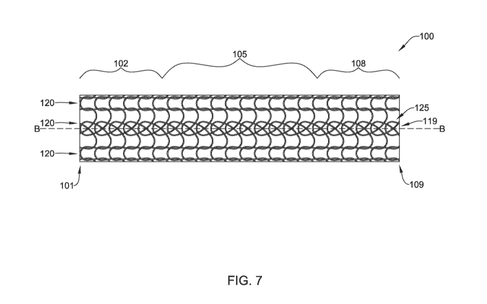
FIG. 7 is a side view illustrating a portion of one example of the knitted
stent 100,
which may include features as discussed above with respect to FIG. 5. In an
alternative
configuration, FIG. 7 may be considered to illustrate a portion of the knitted
stent 200,
which may include features as discussed above with respect to FIG. 6. For the
purpose of
brevity, the following discussion is directed toward the knitted stent 100,
but such
discussion is not intended to be limiting. The knitted stent 100 may include a
first end
portion 102 proximate and/or extending from a first end 101, a second end
portion 108
proximate and/or extending from a second end 109, and a body portion 105
disposed axially
and/or longitudinally between the first end portion 102 and the second end
portion 108
along the central longitudinal axis B-B.
In at least some embodiments, the at least one of the plurality of loop rows
120
including the plurality of closed cells 125 may include a first loop row 119
extending within
the first end portion 102, the body portion 105, and the second end portion
108 along and/or
parallel to the central longitudinal axis B-B. In some embodiments, the first
loop row 119
may extend from the first end 101 of the knitted stent 100 to the second end
109 of the
knitted stent 100 along and/or parallel to the central longitudinal axis B-B.
In some
embodiments, at least some of the plurality of closed cells 125 may be
interwoven and/or
interlaced with each other within the first loop row 119. In some embodiments,
the plurality
of closed cells 125 may be arranged immediately adjacent to each other from
the first end
101 of the knitted stent 100 to the second end 109 of the knitted stent 100
within the first
loop row 119. In some embodiments, every closed cell within the knitted stent
100 may be
disposed within the first loop row 119. In some embodiments, a sum of the
plurality of
cells of the plurality of loop rows 120 in the first end portion 102, the
second end portion
108, and the body portion 105 may comprise at least 90% open cells.
In some embodiments, the plurality of closed cells 125 (e.g., the twisted
loops) may
exert a circumferential force on the first end portion 102, the body portion
105, and/or the
18
CA 03202580 2023-05-18
WO 2022/119891
PCT/US2021/061348
second end portion 108 of the knitted stent 100. In some embodiments, the
plurality of
closed cells 125 (e.g., the twisted loops) may allow a consistent radial force
to be exerted
on the first end portion 102, the body portion 105, and/or the second end
portion 108 of the
knitted stent 100 while maintaining an optional circumferential expansion that
is
appropriate to the vessel dimensions associated with the first end portion
102, the body
portion 105, and/or the second end portion 108 of the knitted stent 100, which
may be
similar or different depending on the anatomical variation.
FIG. 8A is a side view illustrating a portion of another example of the
knitted stent
100, which may include features as discussed above with respect to FIG. 5. In
an alternative
configuration, FIG. 8A may be considered to illustrate a portion of the
knitted stent 200,
which may include features as discussed above with respect to FIG. 6. For the
purpose of
brevity, the following discussion is directed toward the knitted stent 100,
but such
discussion is not intended to be limiting. The knitted stent 100 may include a
first end
portion 102 proximate and/or extending from a first end 101, a second end
portion 108
proximate and/or extending from a second end 109, and a body portion 105
disposed axially
and/or longitudinally between the first end portion 102 and the second end
portion 108
along the central longitudinal axis B-B.
In some embodiments, within the body portion 105, the plurality of loop rows
120
may be formed completely and/or entirely from open cells having an open end
123 disposed
between the two longitudinally oriented connector elements 124 and opposite
the
circumferential loop element 122 (e.g., FIG. 5). In some embodiments, within
the first end
portion 102, at least one of the plurality of loop rows 120 includes a first
plurality of closed
cells having a closed end 127 formed by crossing the two longitudinally
oriented connector
elements 124 at a position opposite the circumferential loop element 122
(e.g., FIG. 5). In
some embodiments, within the second end portion 108, at least one of the
plurality of loop
rows 120 includes a second plurality of closed cells having a closed end 127
formed by
crossing the two longitudinally oriented connector elements 124 at a position
opposite the
circumferential loop element 122 (e.g., FIG. 5).
In at least some embodiments, the at least one of the plurality of loop rows
120
including the plurality of closed cells 125 may include a first portion of a
first loop row 119
and a second portion of the first loop row 119 spaced apart axially and/or
longitudinally
from the first portion. In some embodiments, the first portion of the first
loop row 119 may
extend and/or be disposed within the first end portion 102 along and/or
parallel to the
19
CA 03202580 2023-05-18
WO 2022/119891
PCT/US2021/061348
central longitudinal axis B-B. In some embodiments, the second portion of the
first loop
row 119 may extend and/or be disposed within the second end portion 108 along
and/or
parallel to the central longitudinal axis B-B. The first end portion 102 and
the second end
portion 108 may be spaced apart by the body portion 105 of the knitted stent
100.
As may be seen in FIG 8B, in some embodiments, the first end portion 102 and
the
second end portion 108 may each have an outer diameter that is greater than an
outer
diameter of the body portion 105. In some embodiments, in the radially
expanded
configuration of the knitted stent 100, the first end portion 102 may have a
first outer
diameter greater than the outer diameter of the body portion 105. In such
embodiments,
the first end portion 102 may be considered and/or referred to as a first
flared end portion.
In some embodiments, in the radially expanded configuration of the knitted
stent 100, the
second end portion 108 may have a second outer diameter greater than the outer
diameter
of the body portion 105. In such embodiments, the second end portion 108 may
be
considered and/or referred to as a second flared end portion. In some
embodiments, the
first outer diameter may be the same as the second outer diameter. In some
embodiments,
the first outer diameter may be different from the second outer diameter. In
the example
of FIG. 8B, the first outer diameter and the second outer diameter are both
different from
the outer diameter of the body portion 105. In the example of FIG. 8A, the
first outer
diameter and the second outer diameter are both substantially identical to
(e.g., the same
as) the outer dimeter of the body portion 105. Other configurations are also
contemplated.
For example, the first outer diameter of the first end portion 102 may be
greater than the
outer diameter of the body portion 105 and the second outer diameter of the
second end
portion 108 may be substantially identical to the outer diameter of the body
portion 105, or
vice versa.
With respect to the example configurations of both FIG. 8A and FIG. 8B, in
some
embodiments, the first portion of the first loop row 119 may extend from the
body portion
105 toward and/or to the first end 101 of the knitted stent 100 along and/or
parallel to the
central longitudinal axis B-B, and the second portion of the first loop row
119 may extend
from the body portion 105 toward and/or to the second end 109 of the knitted
stent 100
along and/or parallel to the central longitudinal axis B-B. In some
embodiments, the first
portion may include a first plurality of closed cells 117 and the second
portion may include
a second plurality of closed cells 118. In some embodiments, the plurality of
closed cells
125 (e.g., the twisted loops) described herein may include the first plurality
of closed cells
CA 03202580 2023-05-18
WO 2022/119891
PCT/US2021/061348
117 and/or the second plurality of closed cells 118, and characteristics
and/or features of
each may be used and/or applied interchangeably, unless expressly specified
otherwise.
In some embodiments, the first plurality of closed cells 117 may be interwoven
and/or interlaced with each other within the first loop row 119. In some
embodiments, the
second plurality of closed cells 118 may be interwoven and/or interlaced with
each other
within the first loop row 119. In some embodiments, the first plurality of
closed cells 117
may extend and/or may be arranged immediately adjacent to each other from the
body
portion 105 to the first end 101 of the knitted stent 100 along the central
longitudinal axis
B-B and/or within the first loop row 119. In some embodiments, the second
plurality of
closed cells 118 may extend and/or may be arranged immediately adjacent to
each other
from the body portion 105 to the second end 109 of the knitted stent 100 along
the central
longitudinal axis B-B and/or within the first loop row 119. In some
embodiments, every
closed cell within the knitted stent 100 may be disposed within the first loop
row 119. In
some embodiments, a sum of the plurality of cells of the plurality of loop
rows 120 in the
first end portion 102, the second end portion 108, and the body portion 105
may comprise
at least 90% open cells.
In some embodiments, the first plurality of closed cells 117 (e.g., the
twisted loops)
may exert a first circumferential force on the first end portion 102 of the
knitted stent 100.
In some embodiments, the second plurality of closed cells 118 (e.g., the
twisted loops) may
exert a second circumferential force on the second end portion 108 of the
knitted stent 100.
In some embodiments, the first circumferential force may be substantially
identical to the
second circumferential force. In some embodiments, the first circumferential
force may be
different from the second circumferential force. For example, in some
embodiments, the
first circumferential force may be greater than the second circumferential
force, or vice
versa. In some embodiments, the first plurality of closed cells 117 (e.g., the
twisted loops)
may allow a consistent radial force to be exerted on the first end portion 102
of the knitted
stent 100 while maintaining an optional circumferential expansion that is
appropriate to the
vessel dimensions associated with the first end portion 102 of the knitted
stent 100, which
may be similar or different depending on the anatomical variation. In some
embodiments,
the second plurality of closed cells 118 (e.g., the twisted loops) may allow a
consistent
radial force to be exerted on the second end portion 108 of the knitted stent
100 while
maintaining an optional circumferential expansion that is appropriate to the
vessel
21
CA 03202580 2023-05-18
WO 2022/119891
PCT/US2021/061348
dimensions associated with the second end portion 108 of the knitted stent
100, which may
be similar or different depending on the anatomical variation.
The first flared end portion and/or the second flared end portion may be
configured
to engage the wall of the body lumen. It is contemplated that a transition
from the body
portion to the first flared end portion and/or the second flared end portion
may be gradual,
sloped, or occur in an abrupt stepwise manner, as desired. In some
embodiments, the outer
diameter of the body portion may be in the range of about 15 millimeters to
about 25
millimeters. In some embodiments, the first outer diameter of the first flared
end portion
and/or the second outer diameter of the second flared end portion may be in
the range of
about 20 millimeters to about 30 millimeters. It is contemplated that the
outer diameter of
the knitted stent 100 may be varied to suit the desired application.
FIGS. 9A and 9B are side views illustrating a portion of alternative
configurations
of the knitted stent 100 of FIG. 7. Alternatively, FIGS. 9A and 9B may be
considered to
illustrate a portion of the knitted stent 200. For the purpose of brevity, the
following
discussion is directed toward the knitted stent 100, but such discussion is
not intended to
be limiting. The knitted stent 100 may include a first end portion 102
proximate and/or
extending from a first end 101, a second end portion 108 proximate and/or
extending from
a second end 109, and a body portion 105 disposed axially and/or
longitudinally between
the first end portion 102 and the second end portion 108 along the central
longitudinal axis
B-B.
In some embodiments, a majority of the plurality of loop rows 120 include open
cells having an open end 123 disposed between the two longitudinally oriented
connector
elements 124 and opposite the circumferential loop element 122 (e.g., FIG. 5).
At least one
of the plurality of loops rows 120 includes a plurality of closed cells 125
having a closed
end 127 formed by crossing the two longitudinally oriented connector elements
124 at a
position opposite the circumferential loop element 122 (e.g., FIG. 5). In some
embodiments, the at least one of the plurality of loop rows 120 including the
plurality of
closed cells 125 may include a first loop row 119 extending within the first
end portion
102, the body portion 105, and the second end portion 108 along and/or
parallel to the
.. central longitudinal axis B-B. In some embodiments, the first loop row 119
may extend
from the first end 101 of the knitted stent 100 to the second end 109 of the
knitted stent 100
along and/or parallel to the central longitudinal axis B-B.
22
CA 03202580 2023-05-18
WO 2022/119891
PCT/US2021/061348
In some embodiments, at least some of the plurality of closed cells 125 may be
interwoven and/or interlaced with open cells within the first loop row 119.
For example,
in some embodiments, the plurality of closed cells 125 is longitudinally
spaced apart from
each other within the at least one of the plurality of loops rows 120 and/or
within the first
loop row 119. In some embodiments, the plurality of closed cells 125 is
longitudinally
spaced apart from each other from the first end 101 of the knitted stent 100
to the second
end 109 of the knitted stent 100 within the first loop row 119. In some
embodiments, each
consecutive pair of the plurality of closed cells 125 may be spaced
longitudinally apart from
each other by one open cell within the at least one of the plurality of loops
rows 120 and/or
within the first loop row 119, as shown in FIG. 9A. In some embodiments, each
consecutive pair of the plurality of closed cells 125 may be spaced
longitudinally apart from
each other by two open cells within the at least one of the plurality of loops
rows 120 and/or
within the first loop row 119, as shown in FIG. 9B. Other configurations are
also
contemplated. In some embodiments, every closed cell within the knitted stent
100 may
be disposed within the first loop row 119. In some embodiments, a sum of the
plurality of
cells of the plurality of loop rows 120 in the first end portion 102, the
second end portion
108, and the body portion 105 may comprise at least 90% open cells.
The materials that can be used for the various components of the knitted stent
100/200 and the various elements thereof disclosed herein may include those
commonly
associated with medical devices. For simplicity purposes, the following
discussion makes
reference to the knitted stent 100/200. However, this is not intended to limit
the devices
and methods described herein, as the discussion may be applied to other
elements,
members, components, or devices disclosed herein, such as, but not limited to,
the
expandable framework, the anchoring portion, the body portion, the linking
portion, the
polymeric cover, and/or elements or components thereof
In some embodiments, the knitted stent 100/200, and/or components thereof, may
be made from a metal, metal alloy, polymer (some examples of which are
disclosed below),
a metal-polymer composite, ceramics, combinations thereof, and the like, or
other suitable
material.
Some examples of suitable polymers may include polytetrafluoroethylene (PTFE),
ethylene tetrafluoroethylene (ETFE), fluorinated ethylene propylene (FEP),
polyoxymethylene (POM, for example, DELRINO available from DuPont), polyether
block ester, polyurethane (for example, Polyurethane 85A), polypropylene (PP),
23
CA 03202580 2023-05-18
WO 2022/119891
PCT/US2021/061348
polyvinylchloride (PVC), polyether-ester (for example, ARNITELO available from
DSM
Engineering Plastics), ether or ester based copolymers (for example,
butylene/poly(alkylene ether) phthalate and/or other polyester elastomers such
as
HYTRELO available from DuPont), polyamide (for example, DURETHANO available
from Bayer or CRISTAMIDO available from Elf Atochem), elastomeric polyamides,
block
polyamide/ethers, polyether block amide (PEBA, for example available under the
trade
name PEBAXO), ethylene vinyl acetate copolymers (EVA), silicones, polyethylene
(PE),
MARLEXO high-density polyethylene, MARLEXO low-density polyethylene, linear
low
density polyethylene (for example REXELLO), polyester, polybutylene
terephthalate
(PBT), polyethylene terephthalate (PET), polytrimethylene terephthalate,
polyethylene
naphthalate (PEN), polyetheretherketone (PEEK), polyimide (PI), polyetherimide
(PEI),
polyphenylene sulfide (PPS), polyphenylene oxide (PPO), poly paraphenylene
terephthalamide (for example, KEVLARO), polysulfone, nylon, nylon-12 (such as
GRILAMIDO available from EMS American Grilon), perfluoro(propyl vinyl ether)
(PFA),
ethylene vinyl alcohol, polyolefin, polystyrene, epoxy, polyvinylidene
chloride (PVdC),
poly(styrene-b-isobutylene-b-styrene) (for example, SIBS and/or SIBS 50A),
polycarbonates, polyurethane silicone copolymers (for example, ElastEon0 from
Aortech
Biomaterials or ChronoSil0 from AdvanSource Biomaterials), biocompatible
polymers,
other suitable materials, or mixtures, combinations, copolymers thereof,
polymer/metal
composites, and the like. In some embodiments the sheath can be blended with a
liquid
crystal polymer (LCP). For example, the mixture can contain up to about 6
percent LCP.
Some examples of suitable metals and metal alloys include stainless steel,
such as
304V, 304L, and 316LV stainless steel; mild steel; nickel-titanium alloy such
as linear-
elastic and/or super-elastic nitinol; other nickel alloys such as nickel-
chromium-
molybdenum alloys (e.g., TINS: N06625 such as INCONEL 625, TINS: N06022 such
as
HASTELLOYO C-22t, TINS: N10276 such as HASTELLOYO C276t, other
HASTELLOYO alloys, and the like), nickel-copper alloys (e.g., TINS: N04400
such as
MONELO 400, NICKELVACO 400, NICORROSO 400, and the like), nickel-cobalt-
chromium-molybdenum alloys (e.g., TINS: R30035 such as MP35-1\1 and the
like), nickel-
molybdenum alloys (e.g., TINS: N10665 such as HASTELLOYO ALLOY B2C), other
nickel-chromium alloys, other nickel-molybdenum alloys, other nickel-cobalt
alloys, other
nickel-iron alloys, other nickel-copper alloys, other nickel-tungsten or
tungsten alloys, and
the like; cobalt-chromium alloys; cobalt-chromium-molybdenum alloys (e.g.,
TINS:
24
CA 03202580 2023-05-18
WO 2022/119891
PCT/US2021/061348
R30003 such as ELGILOYO, PHYNOXO, and the like); platinum enriched stainless
steel;
titanium; platinum; palladium; gold; combinations thereof; or any other
suitable material.
In some embodiments, a linear elastic and/or non-super-elastic nickel-titanium
alloy
may be in the range of about 50 to about 60 weight percent nickel, with the
remainder being
.. essentially titanium. In some embodiments, the composition is in the range
of about 54 to
about 57 weight percent nickel. One example of a suitable nickel-titanium
alloy is FHP-
NT alloy commercially available from Furukawa Techno Material Co. of Kanagawa,
Japan.
Other suitable materials may include ULTANIUMTm (available from Neo-Metrics)
and
GUM METALTm (available from Toyota). In some other embodiments, a superelastic
alloy, for example a superelastic nitinol can be used to achieve desired
properties.
In at least some embodiments, portions or all of the knitted stent 100/200,
and/or
components thereof, may also be doped with, made of, or otherwise include a
radiopaque
material. Radiopaque materials are understood to be materials capable of
producing a
relatively bright image on a fluoroscopy screen or another imaging technique
during a
medical procedure. This relatively bright image aids the user of the
endoprosthesis 100/200
in determining its location. Some examples of radiopaque materials can
include, but are
not limited to, gold, platinum, palladium, tantalum, tungsten alloy, polymer
material loaded
with a radiopaque filler, and the like. Additionally, other radiopaque marker
bands and/or
coils may also be incorporated into the design of the endoprosthesis 100/200
to achieve the
same result.
In some embodiments, a degree of Magnetic Resonance Imaging (MRI)
compatibility is imparted into the knitted stent 100/200 and/or other elements
disclosed
herein. For example, the knitted stent 100/200, and/or components or portions
thereof, may
be made of a material that does not substantially distort the image and create
substantial
artifacts (i.e., gaps in the image). Certain ferromagnetic materials, for
example, may not
be suitable because they may create artifacts in an MRI image. The knitted
stent 100/200,
or portions thereof, may also be made from a material that the MRI machine can
image.
Some materials that exhibit these characteristics include, for example,
tungsten, cobalt-
chromium-molybdenum alloys (e.g., UNS: R30003 such as ELGILOYO, PHYNOXO, and
the like), nickel-cobalt-chromium-molybdenum alloys (e.g., TINS: R30035 such
as MP35-
NO and the like), nitinol, and the like, and others.
In some embodiments, the knitted stent 100/200 and/or other elements disclosed
herein may include a fabric material disposed over or within the structure.
The fabric
CA 03202580 2023-05-18
WO 2022/119891
PCT/US2021/061348
material may be composed of a biocompatible material, such a polymeric
material or
biomaterial, adapted to promote tissue ingrowth. In some embodiments, the
fabric material
may include a bioabsorbable material. Some examples of suitable fabric
materials include,
but are not limited to, polyethylene glycol (PEG), nylon,
polytetrafluoroethylene (PTFE,
ePTFE), a polyolefinic material such as a polyethylene, a polypropylene,
polyester,
polyurethane, and/or blends or combinations thereof
In some embodiments, the knitted stent 100/200 and/or other elements disclosed
herein may include and/or be formed from a textile material. Some examples of
suitable
textile materials may include synthetic yarns that may be flat, shaped,
twisted, textured,
pre-shrunk or un-shrunk. Synthetic biocompatible yarns suitable for use in the
present
invention include, but are not limited to, polyesters, including polyethylene
terephthalate
(PET) polyesters, polypropylenes, polyethylenes, polyurethanes, polyolefins,
polyvinyls,
polymethylacetates, polyamides, naphthalene dicarboxylene derivatives, natural
silk, and
polytetrafluoroethylenes. Moreover, at least one of the synthetic yarns may be
a metallic
yarn or a glass or ceramic yarn or fiber. Useful metallic yarns include those
yarns made
from or containing stainless steel, platinum, gold, titanium, tantalum, or a
Ni-Co-Cr-based
alloy. The yarns may further include carbon, glass, or ceramic fibers.
Desirably, the yarns
are made from thermoplastic materials including, but not limited to,
polyesters,
polypropylenes, polyethylenes, polyurethanes, polynaphthalenes,
polytetrafluoroethylenes,
and the like. The yarns may be of the multifilament, monofilament, or spun
types. The
type and denier of the yarn chosen may be selected in a manner which forms a
biocompatible and implantable prosthesis and, more particularly, a vascular
structure
having desirable properties.
In some embodiments, the knitted stent 100/200 and/or other elements disclosed
herein may include and/or be treated with a suitable therapeutic agent. Some
examples of
suitable therapeutic agents may include anti-thrombogenic agents (such as
heparin, heparin
derivatives, urokinase, and PPack (dextrophenylalanine proline arginine
chloromethylketone)); anti-proliferative agents (such as enoxaparin,
angiopeptin,
monoclonal antibodies capable of blocking smooth muscle cell proliferation,
hirudin, and
acetylsalicylic acid); anti-inflammatory agents (such as dexamethasone,
prednisolone,
corticosterone, budesonide, estrogen, sulfasalazine, and
mesalamine);
antineoplastic/antiproliferative/anti-mitotic agents (such as paclitaxel, 5-
fluorouracil,
cisplatin, vinblastine, vincristine, epothilones, endostatin, angiostatin and
thymidine kinase
26
CA 03202580 2023-05-18
WO 2022/119891
PCT/US2021/061348
inhibitors); anesthetic agents (such as lidocaine, bupivacaine, and
ropivacaine); anti-
coagulants (such as D-Phe-Pro-Arg chloromethyl keton, an RGD peptide-
containing
compound, heparin, anti-thrombin compounds, platelet receptor antagonists,
anti-thrombin
antibodies, anti-platelet receptor antibodies, aspirin, prostaglandin
inhibitors, platelet
inhibitors, and tick antiplatelet peptides); vascular cell growth promoters
(such as growth
factor inhibitors, growth factor receptor antagonists, transcriptional
activators, and
translational promoters); vascular cell growth inhibitors (such as growth
factor inhibitors,
growth factor receptor antagonists, transcriptional repressors, translational
repressors,
replication inhibitors, inhibitory antibodies, antibodies directed against
growth factors,
bifunctional molecules consisting of a growth factor and a cytotoxin,
bifunctional
molecules consisting of an antibody and a cytotoxin); cholesterol-lowering
agents;
vasodilating agents; and agents which interfere with endogenous vasoactive
mechanisms.
It should be understood that this disclosure is, in many respects, only
illustrative.
Changes may be made in details, particularly in matters of shape, size, and
arrangement of
steps without exceeding the scope of the disclosure. This may include, to the
extent that it
is appropriate, the use of any of the features of one example embodiment being
used in
other embodiments. The disclosure's scope is, of course, defined in the
language in which
the appended claims are expressed.
27