Note: Descriptions are shown in the official language in which they were submitted.
WO 2022/150619
PCT/US2022/011662
ENHANCED HYDROGEN RECOVERY UTILIZING GAS
SEPARATION MEMBRANES INTEGRATED WITH PRESSURE
SWING ADSORPTION UNIT AND/OR CRYOGENIC SEPARATION
SYSTEM
FIELD OF THE DISCLOSURE
[0001]
Embodiments of the present disclosure generally relate to recovery of
hydrogen
from gas streams.
B AC KGROUND
[0002] Many petrochemical processes use or produce hydrogen (H2), and
the unreacted
or produced hydrogen is generally recovered for recycle or use within the
petrochemical
plant. Currently, hydrogen is commonly recovered from a mixed gas stream using
a
pressure swing adsorption (PSA) unit or cryogenic separation unit, while the
resulting
tail gas is routed to the fuel gas pool.
[0003]
PSA and cryogenic separations have technological limitations with the
maximum amount of H2 which can be recovered. There is always some hydrogen
which is lost in a tail gas stream. A major disadvantage with these
configurations is loss
of hydrogen to a low value stream, resulting in higher overall operating
expense of the
units.
SUMMARY OF THE CLAIMED EMBODIMENTS
[0004]
Embodiments herein integrate gas separation membranes with PSA and/or
cryogenic separations to enhance the overall recovery of hydrogen and minimize
the
loss of high-value hydrogen to the low value fuel gas stream. Such additional
hydrogen
recovery may provide a significant benefit of savings in operating expenses.
This also
concentrates the Carbon Dioxide (CO2) in the resulting tail gas, which makes
carbon
capture from the tail gas stream more efficient and economical.
[0005]
In one aspect, embodiments disclosed herein relate to processes for
recovering
hydrogen. The processes for recovering hydrogen may include feeding a gas
stream,
comprising hydrogen and additional gases, to a pressure swing adsorption (PSA)
system and feeding a membrane permeate stream comprising hydrogen to the PSA
system. In the PSA system, a portion of the hydrogen may be separated from the
additional gases to recover a hydrogen product stream and a PSA tail gas
stream
1
CA 03203126 2023- 6- 21
WO 2022/150619
PCT/US2022/011662
comprising unseparated hydrogen and the additional gases. The PSA tail gas
stream
may be fed to a membrane separation unit for separating hydrogen from the
additional
gases and to recover (i) the membrane permeate stream comprising hydrogen fed
to the
PSA system and (ii) a membrane tail gas stream comprising the additional
gases.
[0006]
In some embodiments, the processes may further include compressing the
pressure swing adsorption tail gas stream upstream of the membrane separation
unit. In
some embodiments, the processes may further include compressing the membrane
permeate stream upstream of the pressure swing adsorption system. Embodiments
of
processes herein may additionally include partially condensing one or both of
the feed
gas stream and the PSA tail gas stream.
[0007]
In another aspect, embodiments disclosed herein relate to systems for
recovering hydrogen. The systems may include a flow line for feeding a gas
stream,
comprising hydrogen and additional gases, to a pressure swing adsorption
system, and
a flow line for feeding a membrane permeate stream comprising hydrogen to the
pressure swing adsorption system. The system also includes the pressure swing
adsorption system, which may be configured for separating a portion of the
hydrogen
from the additional gases and to recover a hydrogen product stream and a
pressure
swing adsorption tail gas stream comprising unseparated hydrogen and the
additional
gases. A flow line may be provided for feeding the pressure swing adsorption
tail gas
stream to a membrane separation unit, which may be configured for separating
hydrogen from the additional gases and to recover (i) the membrane permeate
stream
comprising hydrogen fed to the pressure swing adsorption system and (ii) a
membrane
tail gas stream comprising the additional gases.
[0008]
In some embodiments, the system may also include a compressor for
compressing the pressure swing adsorption tail gas stream upstream of the
membrane
separation unit. In sonic embodiments, the system may further include a
compressor
for compressing the membrane permeate stream upstream of the pressure swing
adsorption system. Embodiments of systems herein may additionally include a
refrigeration/separation system for partially condensing one or both of the
feed gas
stream and the PSA tail gas stream.
2
CA 03203126 2023- 6- 21
WO 2022/150619
PCT/US2022/011662
[0009]
Other aspects and advantages will be apparent from the following
description
and the appended claims.
BRIEF DESCRIPTION OF DRAWINGS
[0010]
Figure 1 is a simplified process flow diagram of a typical pressure swing
adsorption system.
[0011]
Figures 2 and 3 are simplified process flow diagrams of integrated systems
for
recovering hydrogen according to one or more embodiments disclosed herein.
DETAILED DESCRIPTION
[0012] Embodiments herein are directed toward hydrogen recovery from
mixed gas
streams, such as process gas, waste gas, off gas, or tail gas streams from a
petrochemical
process, among others. The mixed gas streams fed for hydrogen recovery may
include,
among other components, hydrogen, carbon dioxide, carbon monoxide, hydrogen
sulfide, sulfur oxides, nitrogen, oxygen, methane, ethane, ethylene, and/or
propane, for
example. While petrochemical streams are noted, embodiments described herein
may
be useful for any hydrogen containing gas stream from which it is desired to
recover
the hydrogen.
[0013]
Current state of art utilizes stand-alone PSA units to recover H,) from the
process
or waste gas stream. Embodiments herein integrate the PSA with a membrane
system,
or integrate PSA and cryogenic separations systems with membrane systems, to
improve the overall H2 recovery. Embodiments herein are thus different from
the
current state of the art in terms of hydrogen recovery parameter and
configuration of
the recovery block.
[0014]
Embodiments herein may locate systems described herein, utilizing membranes
and PSA, on gas streams to recover H2 typically lost in the tail gas stream.
Permeate
from the membrane may be recycled back to the PSA for additional recovery of
H,?. In
some embodiments, cryogenic separation may be utilized for improving the feed
quality
to the membrane systems.
[0015]
A simple block flow diagram of a typical prior art PSA system is shown in
Figure 1. A process gas or waste gas stream 10, which may be any gas stream
targeted
for H2 recovery, may be fed at an appropriate pressure to PSA unit 12 for the
recovery
3
CA 03203126 2023- 6- 21
WO 2022/150619
PCT/US2022/011662
of a hydrogen product 14. Remaining gases, including any unrecovered H2, is
routed
as tail gas stream 16, which is typically utilized as a fuel gas in the unit.
As noted
above, the overall recovery of hydrogen from a PSA unit results in a
substantial loss of
hydrogen in tail gas stream 16. PSA units can typically recover 85-90% of the
hydrogen
in the feed stream, while the balance of hydrogen is permanently lost in the
tail gas.
[0016]
Embodiments herein may enhance the recovery of H2 in the tail gas stream by
appropriately incorporating membrane separation within the recovery systems. A
tail
gas may be fed to a membrane separation unit at an appropriate pressure. If
necessary,
a compressor can be utilized for pressurizing the gas as required by the
membrane
system for the targeted H2 recovery and purity. A hydrogen rich permeate
stream from
the membrane may then be recycled back to the PSA unit for additional recovery
of 1-1/
in the final PSA product while the retentate stream may be recovered as a tail
gas stream
from the complex and can be utilized as a fuel gas stream, routed to carbon
capture, or
used for some other purpose.
[0017]
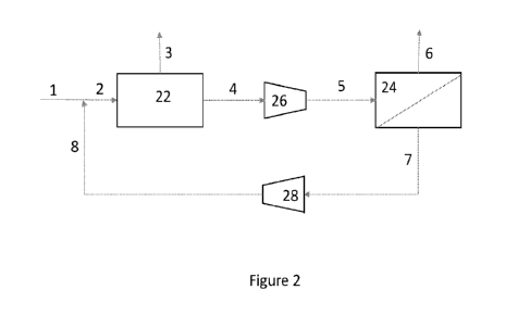
Referring now to Figure 2, a simplified process flow diagram of a system
for
recovering hydrogen according to embodiments herein is illustrated. A process
gas or
waste gas stream 1, 2, which may be any gas stream targeted for H2 recovery,
may be
fed at an appropriate pressure, such as 25 to 35 barg, to PSA unit 22 for the
recovery of
a hydrogen product 3 and remaining gases 4.
[0018]
The remaining gases in stream 4, including any unrecovered H2, may be
routed
via flow stream 4 to a membrane separation system 24. If necessary, a
compressor 26
may be used to increase a pressure of the remaining gases in stream 4,
producing a
pressurized remaining gas stream 5 that may be fed to the membrane separation
system
24. For example, the remaining gases may be recovered in stream 4 at a
pressure in the
range of 1 to 5 barg, and the pressure of the remaining gases may be increased
to a
pressure in the range of 10 to 20 barg and then fed via flow stream 5 to the
membrane
separation system 24.
[0019]
In membrane separation system 24, a membrane is used to separate the
hydrogen from other gases in the remaining gas stream 4, 5. The hydrogen
permeate
may be recovered via flow stream 7, while the retentate stream, gases that do
not
permeate through the membrane, may be recovered as a tail gas stream 6.
Hydrogen
4
CA 03203126 2023- 6- 21
WO 2022/150619
PCT/US2022/011662
permeate 7 may then be recycled to the pressure swing adsorption unit 22 for
recovery
of the hydrogen along with feed stream 1. If necessary, a compressor 28 may be
used
to increase a pressure of the hydrogen in permeate stream 7, producing a
pressurized
permeate stream 8 that may be fed to the PSA unit 22. For example, the
hydrogen rich
permeate stream 7 may be recovered from the membrane separation system 24 at a
pressure in the range from 1 to 2 barg and may be recycled back to the PSA
unit for
additional recovery of hydrogen in the final product. The retentate stream,
tail gas
stream 6, may be recovered at a higher pressure, such as in the range of 8 to
18 barg,
and this tail gas stream from the complex may be used as a fuel gas stream,
routed for
carbon capture, or as some other purpose gas.
[0020]
While membranes may be used that primarily recover FL in the permeate, some
other gases may also be recovered along with H2 in the permeate stream 7.
These gases
will build to a steady state concentration in the system and are eventually
removed in
the PSA unit and finally leave the system via tail gas stream 6.
[0021]
Membrane separation system 24 may recover 70% to 90% of the hydrogen in
the PSA tail gas 4, resulting in an overall hydrogen recovery from systems
similar to
that as depicted in Figure 2 in the range of 96 to 99%.
[0022]
In some embodiments, the process or waste gases may include condensable
components, such as light hydrocarbons (methane, ethane, etc.) or other
heavier gases.
In some such embodiments, cryogenic separations can be utilized on the tail
gas stream
from the PSA unit for condensing the heavier hydrocarbons while the light ends
can be
processed in the membrane system. Processing higher purity 1-17 gas streams in
the
membrane unit may provide better H2 recovery and purity. The benefit of higher
purity
H2 can also be utilized in operating the membrane system at a lower pressure
while
achieving a hydrogen recovery similar to that achieved in configurations
without
chillers. Cryogenic separations can also beneficially reduce the concentration
of
components that may impact the performance of membranes or that are
incompatible
with the membrane material.
[0023]
Referring now to Figure 3, a simplified process flow diagram of a system
integrating cryogenic separations, PSA, and membrane separations for
recovering
CA 03203126 2023- 6- 21
WO 2022/150619
PCT/US2022/011662
hydrogen according to embodiments herein is illustrated, where like numerals
represent
like parts.
[0024]
Similar to the embodiment of Figure 2, a process gas or waste gas stream 1,
2,
which may be any gas stream targeted for H2 recovery. may be fed at an
appropriate
pressure to PSA unit 22 for the recovery of a hydrogen product 3. Remaining
gases,
including any unrecovered H2, may be routed via flow stream 4 to a membrane
separation system 24. In membrane separation system 24, a membrane is used to
separate the hydrogen from other gases in the remaining gas stream 4. The
hydrogen
permeate may be recovered via flow stream 7, while the retentate stream, gases
that do
not permeate through the membrane, may be recovered as a tail gas stream 6.
Hydrogen
permeate 7 may then be combined with process or waste gas stream 1 and
recycled to
the pressure swing adsorption unit 22 for recovery of the hydrogen via flow
line 2.
[0025]
To enhance the separations in each of the PSA unit 22 and the membrane
separation system 24, a cryogenic separation system 31 may be used. A feed
stream
32, such as a lean process gas or waste gas stream including hydrogen and
condensable
components, such as light hydrocarbons, may be cooled in a chiller 33.
reducing a
temperature of the gas stream 32 and condensing a portion of the condensable
components. The resulting cooled feed stream 35 may be fed to a vapor-liquid
separator
37, such as a flash drum, distillation column, or the like, to separate any
condensed
components from the vapors. The condensed components may be recovered as a
bottoms liquid stream 39, and the uncondensed vapors may be recovered as an
overhead
stream 41. Overhead stream 41 may then be passed through chiller 33, producing
the
process gas stream or waste gas stream 1 fed to the PSA unit 22.
[0026]
In addition to unrecovered hydrogen, PSA tail gas stream 4 may also contain
condensable components, such as any light hydrocarbons not condensed and
recovered
in vapor-liquid separator 37. The PSA tail gas stream 4 may be cooled to
condense at
least a portion of the condensable components and fed to a second vapor-liquid
separator 43, recovering a second overhead stream 49 and a second bottoms
stream 50.
[0027]
Cooling of the PSA tail gas stream may occur, for example, using cross-
exchange in chiller 33 and/or a second chiller 45. In some embodiments, the
PSA tail
gas stream is initially processed through chiller 33, then fed via stream 47
to chiller 45
6
CA 03203126 2023- 6- 21
WO 2022/150619
PCT/US2022/011662
and cross-exchanged with the second vapor-liquid separator 43 overhead stream
49.
Following cross-exchange, the chilled PSA tail gas stream 51 may be fed to the
second
vapor-liquid separator 43 for separation of the condensed components,
recovered via
flow lint 50, from the uncondensed PSA tail gas components, recovered via
overhead
stream 49.
[0028]
Following cross-exchange in chiller 45 and/or chiller 33, the overhead
stream
49 (uncondensed PSA tail gas) may be fed via flow stream 55 to the membrane
separation unit 24 and processed as described above. The condensed components
recovered from separators 37, 43 via flow lines 39, 50 may be combined,
forming a
combined condensate stream 57. Combined condensate stream 57 may be expanded
or
otherwise used for cross-exchange in chiller 33 and recovered as a fuel gas
product
stream 59.
[0029]
While not illustrated in Figure 3, one or both of chillers 33, 45 may
include a
refrigerant feed stream to provide the desired refrigeration and cooling of
the desired
streams. Additionally, or alternatively, various streams may be compressed
and/or
expanded to provide a desired amount of refrigeration within chillers 33, 45
to result in
the partial condensation.
[0030]
As an example, a lean process gas stream 32 at a pressure of 20-30 barg is
chilled in chiller 33 to a temperature of -37 C to -60 C using an appropriate
refrigerant,
such as propylene and/or ethylene or any combination of refrigeration provided
by a
refrigerant stream or process streams. The cooled feed stream 35 may then be
flashed
in vapor-liquid separator 37 operating at pressure of 20-30 barg. Vapor 41
from the
separator is heated back to temperature in the range of 35-45 C before it is
sent via flow
stream 1, 2 to PSA unit 22 for recovery of hydrogen product stream 3.
[0031]
Remaining gas 4 from PSA unit 22 is further cooled in a series of chillers
using
methane/propylene/ethylene or any combination refrigeration to a temperature
in the
range of -60 C to -98 C. For example, remaining gas 4 may be initially cooled
in
exchanger 33 and further cooled in exchanger 45, producing cooled remaining
gas
stream 51. Remaining gas stream 51 may then be flashed in vapor-liquid
separator 43.
Vapor from separator 43 is heated back to a temperature of 35-45 C in the
cross-
exchangers / chillers 45, 33 and then sent via flow line 55 to membrane
separation unit
7
CA 03203126 2023- 6- 21
WO 2022/150619
PCT/US2022/011662
24. Hydrogen rich permeate 7 from membrane separation unit 24 is then
compressed
and recycled back to PSA unit 22 for additional hydrogen recovery while
retentate 6 is
sent as the system tail gas to a fuel gas header.
[0032]
While Figure 3 illustrates two cross-exchangers 33, 45, and two vapor-
liquid
separators 37, 43, additional exchangers and separators at lower temperatures
may be
utilized, depending on the need to purify the H2 in the remaining gas 4 from
the PSA
unit or based on the need to concentrate the H2 in the feed 55 to the membrane
separation unit 24.
[0033]
The combination of PSA, cryogenic separation and membranes according to
embodiments herein can provide an overall H2 recovery in the range of 96-99%.
[0034]
Integrating the cryogenic separations, such as in the embodiment of Figure
3,
may condense the heavier hydrocarbons while the light ends, including hydrogen
and
other non-condensable components present in the process or waste gas, can be
processed in the membrane system. This may result in the processing of a feed
gas
stream having a higher purity in the membrane unit, which may provide better
H2
recovery and purity. The benefit of higher purity H9 can also be utilized in
operating
the membrane system at lower pressure.
[0035]
For all these configurations, the membrane system can be a single or
multiple
stage system, depending on the requirement of I-1/ purity and I+ recovery in
the
membrane permeate. 117 purity and recovery across membrane impacts the overall
recovery of H2 across the membrane integrated PSA system.
[0036]
Embodiments herein may also be extended to other modes of H2 recovery
processes. H2 is also recovered via cryogenic separation where refrigerant is
utilized
for recovering H2. In such embodiments, membranes can be utilized for enhanced
recovery of H2 thereby reducing the load on refrigeration system resulting in
better
economics of the process.
[0037]
The tail gas streams 7 produced via processes as illustrated in Figures 2
and 3
may be used, as noted above, as a fuel gas or for some other process gas.
Alternatively,
the tail gas streams, containing carbon monoxide, carbon dioxide, or other
carbon-
containing molecules, may be fed to a carbon capture unit. The higher recovery
of
8
CA 03203126 2023- 6- 21
WO 2022/150619
PCT/US2022/011662
hydrogen resulting from processes described herein may result in a lesser
quantity of
tail gas to the downstream carbon capture unit. Further, the lower quantity,
or near
absence of hydrogen, also helps in concentrating the carbon dioxide in the
feed to the
carbon capture unites, resulting in a more efficient decarbonization. The
lower
concentration and quantity of hydrogen may also result in smaller process unit
sizes
required for the carbon capture units, leading to reduces capital costs for
such units.
[0038]
As described above, embodiments herein utilize PSA and/or cryogenic
separations with membrane separations to improve hydrogen recovery from mixed
gas
streams. Improved hydrogen recovery will provide the benefit of savings in
operating
expenses of the associated plant by avoiding loss of high value hydrogen to
the low
value fuel gas pool. Additionally, this will also help in making the tail gas
decarbonization (carbon capture from the tail gas) more efficient and smaller
in
capacity.
[0039]
Unless defined otherwise, all technical and scientific terms used have the
same
meaning as commonly understood by one of ordinary skill in the art to which
these
systems, apparatuses, methods, processes and compositions belong.
[0040]
The singular forms "a," "an," and "the" include plural referents, unless
the
context clearly dictates otherwise.
[0041]
As used here and in the appended claims, the words "comprise," "has," and
"include" and all grammatical variations thereof are each intended to have an
open,
non-limiting meaning that does not exclude additional elements or steps.
[0042]
"Optionally" means that the subsequently described event or circumstances
may
or may not occur. The description includes instances where the event or
circumstance
occurs and instances where it does not occur.
[0043]
When the word "approximately" or "about" are used, this term may mean that
there can be a variance in value of up to 10%, of up to 5%, of up to 2%, of
up to 1%,
of up to 0.5%, of up to 0.1%, or up to 0.01%.
[0044]
Ranges may be expressed as from about one particular value to about another
particular value, inclusive. When such a range is expressed, it is to be
understood that
9
CA 03203126 2023- 6- 21
WO 2022/150619
PCT/US2022/011662
another embodiment is from the one particular value to the other particular
value, along
with all particular values and combinations thereof within the range.
[0045]
While the disclosure includes a limited number of embodiments, those
skilled
in the art, having benefit of this disclosure, will appreciate that other
embodiments may
be devised which do not depart from the scope of the present disclosure.
Accordingly,
the scope should be limited only by the attached claims.
CA 03203126 2023- 6- 21