Note: Descriptions are shown in the official language in which they were submitted.
1
Transport container
The invention relates to a transport container for
transporting temperature-sensitive goods to be transported,
having a container wall arrangement surrounding an interior
chamber for receiving the goods to be transported
comprising a plurality of walls adjoining one another at an
angle, the container wall arrangement having an opening for
loading and unloading the interior chamber, which opening
can be closed by means of a door device, and the container
wall arrangement enclosing the interior chamber on all
sides with the exception of the opening.
When transporting temperature-sensitive goods, such as
pharmaceuticals, over periods of several days, specified
temperature ranges must be maintained during storage and
transport in order to ensure the usability and safety of
the goods being transported. Temperature ranges of -60 C to
-80 C are specified as storage and transport conditions for
various drugs and vaccines.
To ensure that the desired temperature range of the
transported goods is permanently and verifiably maintained
during transport, transport containers, e.g. air freight
containers, with special insulation properties are used.
The technical implementation of transport containers for
the temperature range -60 C to -80 C is usually carried out
with insulated containers in combination with a coolant.
For insulation, layered wall constructions of standard
insulation material such as EPS, PIR or XPS as well as
high-performance insulation such as vacuum panels (VIP) are
used.
CA 03203681 2023- 6- 28
2
Dry ice (solid CM is used as a coolant, which is ideal
for this temperature range due to the sublimation
temperature of approx. -78.5 C. In addition, an amount of
energy of 571.1 kJ/kg is required for the phase transition
from solid to gas (sublimation), which enables a very large
cooling effect at low weight compared to commercially
available phase change material in a similar temperature
range (=,--200 kJ/kg). Another advantage of dry ice is its
residue-free dissolution. The only thing that has to be
ensured is a safe outflow of the gaseous carbon dioxide,
which at normal pressure and a temperature of 0 C takes up
about 760 times the volume of the dry ice. For air
transport, there are usually maximum sublimation rates or
dry ice quantities per flight which must not be exceeded.
Minimizing the amount of dry ice used per kg of cargo
therefore directly affects the total amount of cargo
allowed per flight.
There are different approaches for positioning the dry ice
inside the transport container. In one variant, the dry ice
is placed on or inside the transported goods. The advantage
of this procedure is that the temperature of the goods is
very constant at about -78 C. One disadvantage is that a
large amount of dry ice must be used to achieve uniform
coverage of the transported goods and fill the gaps.
Another disadvantage is that the amount of dry ice required
depends on the goods being transported and the packaging.
In addition, the transit time of the transport container is
limited by a local temperature deviation in the case of
asymmetric heat input. The rest of the dry ice effectively
goes unused.
CA 03203681 2023- 6- 28
3
In another variant, the dry ice is placed in disc form
around the goods on all sides and at the top and bottom of
the transport container. The advantage here is also the
uniform temperature distribution. However, if an asymmetric
heat input occurs (e.g., due to solar radiation from
above), the transit time of the entire transport container
is also limited here by the point at which the dry ice
first sublimates completely. On the sides with lower heat
input, part of the dry ice remains unused. Nevertheless, in
order to achieve the desired runtime, a large amount of dry
ice is required, with only a certain amount effectively
needed. Furthermore, with regard to manual handling, it is
time-consuming to introduce the dry ice on all sides, as
well as at the top and bottom of the transport container,
before each transport. In addition, it is not readily
possible to extend the service life of the transport
container by replacing the dry ice, as this requires the
container to be completely disassembled.
Another problem with the use of dry ice is that the inner
walls of the transport container are usually made of
plastic or cardboard, so that heat distribution in the
interior chamber takes place only through the transported
goods themselves and via natural convection in the interior
chamber. The heat flow over the transported goods is given
by the average thermal conductivity of the goods and the
packaging and cannot be guaranteed. The transported goods
must therefore have a certain distance to the side walls,
the rear wall and the floor, so that air circulation is not
impeded and an even temperature distribution can be
achieved by natural convection. This has the disadvantage
that not all of the interior chamber can be used for the
transported goods.
CA 03203681 2023 6 28
4
The present invention is intended to provide a transport
container for the temperature range -60 C to -80 C, which
has the following properties. The dry ice introduced should
be used as efficiently as possible. This means that at the
end of the runtime, which is defined by the time of the
first temperature deviation above -60 C in the interior
chamber, as large a proportion as possible of the dry ice
should have sublimed. Due to the limitations on the amount
of dry ice allowed in air transport, this is critical to
the total amount of cargo that can be transported per
flight.
It should also be possible to use the entire interior
chamber of the transport container for the goods to be
transported. No gaps or shafts should be required for air
circulation. Placing the dry ice in the transport container
before transport should be as simple as possible. After
transport, it should also be possible to extend the runtime
by renewing the dry ice without having to disassemble the
transport container or remove the transported goods.
The structure and the materials used should be able to
withstand the low temperatures, absorb the mechanical
forces due to thermal stresses and loads during transport,
and at the same time be as light as possible.
To solve this problem, the invention essentially provides,
in a transport container of the type mentioned at the
beginning, that the container wall arrangement consists of
a layered structure comprising, from the outside to the
inside: a first insulation layer, optionally a second
insulation layer, and an energy distribution layer bounding
CA 03203681 2023- 6- 28
5
the interior chamber and made of a material having a
thermal conductivity of > 100 W/(m.K), and that at least
one coolant reservoir for holding a coolant is arranged
and/or fastened in the interior chamber on at least one
wall, in particular an upper wall.
By combining a coolant reservoir for holding a coolant,
such as dry ice, arranged and/or attached to at least one
wall in the interior chamber with an energy distribution
layer bounding the interior chamber, efficient heat
distribution is achieved over the entire interior envelope
so that the amount of coolant can be minimized. Due to the
heat distribution, it is sufficient here to arrange the
coolant on only one wall. However, it is also conceivable
to provide the coolant on two or more walls. The highly
thermally conductive inner shell allows very efficient use
of the dry ice, with heat inputs at any position of the
transport container being conducted to the coolant and
absorbed there, thus compensating for asymmetric heat input
and avoiding one-sided sublimation of the dry ice. The
coolant quantity can be selected in such a way that the
coolant is almost completely used up at the end of the
running time.
Preferably, the at least one coolant reservoir or its
support is in direct thermally conductive contact with the
energy distribution layer, the thermally conductive contact
preferably having a thermal conductivity of > 100 W/(m.K).
The energy distribution layer bounding the interior chamber
is preferably in direct contact with the interior chamber,
so that direct heat transfer between the interior chamber
and the energy distribution layer is ensured.
CA 03203681 2023- 6- 28
6
Since convection is not required for heat distribution over
the entire interior volume, the interior chamber can be
used entirely for the payload. No air gaps or shafts are
needed to maintain air circulation.
The highly efficient dry ice utilization by internal heat
distribution in combination with a two-layer insulation of
the container wall arrangement results in a running time of
more than 100-140h at an average outside temperature of
30 C with a dry ice quantity of 80-120 kg and a payload
volume of 1 to 1.5m3 with an outer volume of 2-4m3. Compared
to conventional solutions, this is a significant
improvement by a factor of 2 to 20. Thus, a payload volume
of 1 to 1.5m3 per RKN aircraft position can be achieved or
4 transport containers can be arranged on a PMC pallet with
a total payload volume of 4x1.5m3 or 6m3.
As far as the layered structure of the container wall
arrangement is concerned, it is preferably provided that
the first insulation layer, the second insulation layer, if
present, and the energy distribution layer lie directly on
top of each other.
Preferably, the first insulation layer, the second
insulation layer (if present) and the energy distribution
layer enclose the interior chamber on all sides and without
interruption, with the exception of the opening. The energy
distribution layer completely surrounds the interior
chamber with the exception of the opening, i.e. each wall
of the container wall arrangement comprises the energy
distribution layer as the innermost layer, the energy
distribution layers of all walls being thermally
CA 03203681 2023- 6- 28
7
conductively connected to one another in the adjacent edges
and corners, i.e. by means of a joint which has a thermal
conductivity of > 100 W/(m.K).
Preferably, the door device also consists of the layered
structure used for the container wall arrangement. In
particular, the door device consists of a layered structure
comprising, from the outside to the inside: a first
insulation layer, optionally a second insulation layer, and
an energy distribution layer bounding the interior chamber
and made of a material with a thermal conductivity of > 100
W/(m.K).
For sufficient heat distribution, a thermal conductivity of
the energy distribution layer of at least 100 W/(m.K) is
specified. The higher the thermal conductivity of the
energy distribution layer is selected, the more efficient
is the utilization of the coolant. According to a preferred
embodiment, it may be provided that the thermal
conductivity of the energy distribution layer of the
container wall arrangement and/or the door device is at
least 140 W/(m.K), more preferably at least 180 W/(m.K).
The energy distribution layer of the container wall
arrangement and/or the door device can be made, for
example, of aluminum, of graphite or of a graphite
composite material, in particular graphite sheets coated on
both sides with carbon fiber-reinforced plastic. Such
materials also result in mechanical reinforcement of the
container wall arrangement at low weight.
In the case of aluminum, 0.5-5 mm thick aluminum plates can
be used, which have a thermal conductivity of about 150
W/(m.K), distributing local heat input over the inner shell
CA 03203681 2023 6 28
8
and creating a uniform temperature distribution in the
interior chamber. The joints of the individual aluminum
plates on the sides and corners may be reinforced with
rivets so that they can withstand the forces generated by
thermal stresses.
In the case of the carbon graphite composite sheet energy
distribution layer design, for example, composite sheets
may consist of a 0.2-1 mm thick graphite core laminated on
both sides with 0.2-2 mm thick sheets of carbon fiber
reinforced plastic (CFRP). Since graphite exhibits thermal
conductivities of up to 400 W/(m.K) depending on density,
similar or higher average thermal conductivities can be
achieved with carbon graphite composite panels than with
comparable aluminum panels. In addition, CFRP has a better
mechanical strength-to-weight ratio than aluminum, which
enables weight savings. Another advantage of carbon
graphite composite sheets is the low coefficient of thermal
expansion of CFRP. Typical values in the fiber direction
are cxcFK = 0.6.10-6 K-1. For comparison, the coefficient of
thermal expansion of a common aluminum alloy: aEN-AW
5754 = 23.8.10-6 K-1. This reduces thermal stresses and the
resulting mechanical loads on the inner shell.
In a particularly preferred manner, the at least one
coolant reservoir is designed as a drawer which is guided
in a drawer guide so that it can be extracted from the
interior chamber and insserted into the interior chamber.
Such a design allows extremely simple handling, in which
the coolant can be filled or renewed without having to
disassemble the transport container or remove the
transported material. The running time of the transport
CA 03203681 2023 6 28
9
container can be extended as required by refilling the
coolant.
Preferably, the drawer(s) has/have such dimensions that the
entire surface of one wall of the container wall
arrangement is covered.
Preferably, the at least one coolant reservoir, in
particular the drawer(s) as well as the drawer guide, which
is attached to at least one wall, is also made of a highly
heat-conductive material so that the heat introduced is
distributed evenly over the coolant. Here, it is preferably
provided that the at least one coolant reservoir is made of
a material with a thermal conductivity of > 100 W/(m.K),
preferably > 140 W/(m.K), in particular > 180 W/(m.K), for
example aluminum, graphite or a graphite composite
material, in particular graphite sheets coated on both
sides with carbon fiber-reinforced plastic.
Thermal insulation of the transport container is achieved
by a first and, if necessary, a second insulation layer.
The structure of the container wall arrangement with at
least two insulation layers allows each insulation layer to
be optimized with regard to its respective insulation
function. Preferably, one of the insulation layers, in
particular the first, outer insulation layer, is designed
to minimize the heat transfer to the interior chamber that
occurs via thermal radiation. The other insulation layer,
in particular the second, inner insulation layer, may be
formed to minimize heat transfer to the interior chamber
that occurs via solid-state heat conduction.
CA 03203681 2023- 6- 28
10
Preferably, the first insulation layer may have a thermal
conductivity of 4 to 300 mW/(m.K) and the second insulation
layer may have a thermal conductivity of 1 to 30 mW/(m.K),
with the first insulation layer preferably having a higher
thermal conductivity than the second insulation layer.
This can result in a U-value for the transport container of
0.1-0.2 W/m2K, which corresponds to a very low heat input
compared to transport containers commonly used in the
industry.
With respect to the design of one of the insulation layers,
preferably the first insulation layer, as a barrier against
thermal radiation, it may comprise a heat-reflective coated
carrier material, such as a carrier material provided with
a metal coating. Preferably, the heat-reflecting coating is
formed by a metallic, in particular gas-tight coating,
preferably a coating with an emissivity of < 0.5,
preferably < 0.2, particularly preferably < 0.04, such as a
coating of aluminum. Preferably, it is provided that said
insulation layer comprises a multilayer structure of
honeycomb-shaped thermoformed plastic films, which is
provided on both sides with a heat-reflective coating, in
particular of aluminum. An advantageous design results if
said insulation layer has a plurality of, in particular,
honeycomb-shaped hollow chambers, a honeycomb structural
element according to WO 2011/032299 Al being particularly
advantageous. Alternatively, said insulation layer may be
made of a conventional porous insulation material, such as
polyurethane, polyisocyanurate or expanded polystyrene.
Said insulation layer preferably has a thickness of 60-80
mm.
CA 03203681 2023- 6- 28
11
With regard to the design of the other insulation layer,
preferably the second insulation layer, as a barrier
against solid-state heat conduction, it may preferably be
designed as vacuum thermal insulation and preferably
comprise or consist of vacuum insulation panels.
The second insulation layer preferably has a thickness of
30-50 mm.
Preferably, the vacuum insulation panels have a porous core
material as a support body for the vacuum present inside
and a gas-tight envelope surrounding the core material, the
core material preferably consisting of an aerogel, open-
pore polyurethane or open-pore polyisocyanurate. The
advantage of these core materials over conventional fumed
silica is their lower density, which can result in weight
savings over conventional vacuum panels. The density of
aerogel, for example, is in the range 80-140kg/m3, whereas
fumed silica usually has a density of 160-240 kg/m3. This
with similar thermal conductivity properties in the range
2-6 mW/(m.K).
Alternatively, the latter insulation layer may have an
outer wall, an inner wall spaced therefrom, and a vacuum
chamber formed between the outer and inner walls, the
vacuum chamber being in the form of a continuous vacuum
chamber surrounding the interior chamber on all sides
except for the opening. This insulation layer of the
container wall arrangement is thus designed as a double-
walled vacuum container, which surrounds the interior
chamber on all sides with the exception of the container
opening. Therefore, unlike the use of conventional vacuum
panels, the insulation does not consist of individual
CA 03203681 2023- 6- 28
12
vacuum elements that have to be assembled into an envelope,
but includes in one part all sides of the transport
container except for the opening. Since a continuous vacuum
chamber is formed between the inner and outer walls of the
insulation layer, surrounding the interior chamber on all
sides except for the opening, joints between the separate
vacuum panels that would otherwise be required and the
associated thermal bridges can be avoided. The double-
walled design of the insulation layer is also self-
supporting, so in addition to insulation it also has a
stabilizing function. This means that load-bearing
structural parts can be saved.
The term "vacuum chamber" means that the space between the
inner and outer walls of the insulation layer is evacuated,
thereby achieving thermal insulation by reducing or
eliminating the heat conduction of the gas molecules
through the vacuum. Preferably, the air pressure in the
vacuum chamber is 0.001-0.1 mbar.
Preferably, the outer and inner walls are made of a metal
sheet, in particular stainless steel, aluminum or titanium,
and preferably have a thickness of 0.01 to 1 mm. This
ensures the required stability on the one hand and the gas-
tight design of the walls on the other. In such an
embodiment, the inner wall of the insulation layer, when
arranged as the second insulation layer, may simultaneously
form the energy distribution layer.
In order to be able to withstand the compressive forces of
the surrounding air without having to make the outer and
inner walls excessively thick, the outer wall and the inner
wall are preferably connected by a plurality of spacers,
CA 03203681 2023- 6- 28
13
which are preferably made of a synthetic material with a
thermal conductivity of < 0.35 W/(m-K), such as
polyetheretherketone or aramid. The spacers ensure the
desired distance between the outer and inner walls so that
the intervening cavity, i.e. the vacuum chamber, remains.
Since the spacers form thermal bridges, it is advantageous
to make them from a material with the lowest possible
thermal conductivity.
In order to further increase the thermal insulation
performance of the insulation layer, a preferred further
development provides that a plurality of spaced-apart
insulation foils are arranged in the vacuum chamber, the
film plane of which is substantially parallel to the plane
of the outer and inner walls. In particular, the insulating
foils are in stacked form, preferably with a stack of foils
arranged in each wall of the container wall arrangement and
extending substantially across the entire wall. Preferably,
the insulation foils are arranged so that they surround the
interior chamber on all sides except for the opening.
Preferably, the insulation foils are arranged in such a way
that a gap (protective space) remains between the inner
surface of the outer or inner wall facing the vacuum
chamber and the foil stack in each case, so that the foil
stack is not compressed by any deformation of the walls. In
addition, the distance provides space for constructive
stabilization of the spacers and facilitates vacuuming.
A further preferred design provides that the insulating
foils are held at a distance from one another by flat
spacer elements, the flat spacer elements preferably being
CA 03203681 2023- 6- 28
14
formed by a textile sheet material, in particular in the
form of a polyester nonwoven.
In particular, the insulation foils can be designed as
metal-coated or -vaporized plastic foils. Such insulation
foils are also called superinsulation foils. For example,
the metal coating is made of aluminum.
The overall performance of the insulation of the transport
container naturally depends also on the thermal insulation
properties of the door device closing the opening of the
interior chamber. As already mentioned, the door device can
here consist of a layered structure corresponding to the
layered structure of the container wall arrangement and
comprising, from the outside to the inside, a first
insulation layer, a second insulation layer and an energy
distribution layer bounding the interior chamber and made
of a material with a thermal conductivity of > 100 W/(m.K).
In a particularly preferred embodiment, the door device
includes at least one inner door panel and at least one
outer door panel. In particular, the door panels are hinged
doors attached to the transport container by means of a
hinge. The formation of at least one outer door panel and
at least one inner door panel gives rise to a two-layer
construction, in which the at least one outer door panel
preferably forms the first insulation layer of the door
device and the at least one inner door panel forms the
second insulation layer of the door device, reference being
made to the functions and properties described above in
connection with the insulation layers of the container wall
arrangement with respect to the properties and construction
of the first and second insulation layers.
CA 03203681 2023- 6- 28
15
The at least one outer door panel and the at least one
inner door panel can preferably be opened and closed
separately and independently of each other. The double-
walled construction of the door device results in a
temperature around 0 C (between -20 C and 8 C) on the
outside of the at least one inner door panel when the
interior temperature is -60 C to -80 C. This makes it
possible to open the inner door panel by hand (i.e. without
the risk of cold burns) during operation. Preferably, this
effect is achieved by the at least one inner door panel
having a higher insulating performance (1 to 30 mW/(m.K))
than the at least one outer door panel (4 to 300 mW/(m.K)).
In a preferred embodiment, the door device includes a
single outer door panel and two inner door panels to form
an inner double door.
The structure of the door device consisting of at least one
outer and at least one inner door panel further allows the
coolant to be renewed in the closed state of the at least
one inner door panel, i.e. to be refilled into the coolant
reservoir. For this purpose, it is preferably provided that
the at least one inner door panel is arranged to keep the
coolant reservoir accessible via the opened outer door
panel when the at least one inner door panel is closed.
In this embodiment, the inner door panel or inner double
door can be made smaller, for example, so that the coolant
reservoir(s) can be opened when the inner door is closed.
In the case of the design of the coolant reservoir as a
drawer, it can be pulled out of its holder when the inner
door is closed. This has the advantage that the running
CA 03203681 2023- 6- 28
16
time of the transport container can be extended as required
by renewing the coolant. In this case, the inner double
door does not have to be opened and the transported goods
do not have to be taken out.
From a constructional point of view, the at least one
coolant reservoir can be kept accessible when the inner
door panel is closed by the coolant reservoir having an
access portion arranged in the opening of the container
wall arrangement and by the at least one inner door panel
cooperating with the access portion on the side facing the
access portion in its closed state to sealably close off
the interior chamber. For example, the design may be such
that the inner door panel is substantially flush with a
front face of the access portion. In this context, the
access portion is the section or side of the coolant
reservoir through which the coolant reservoir must be
accessible for refilling the coolant. In the case of a
drawer, for example, it is the drawer front that is gripped
to pull the drawer out of the interior chamber of the
transport container.
In order to ensure optimum thermal insulation in the area
of the access portion, it is preferably provided that the
coolant reservoir has vacuum thermal insulation on the
front side facing the opening of the container wall
arrangement.
When transporting transport containers by air, transport
containers must allow for pressure equalization between the
interior of the transport container and the pressurized
cabin of the aircraft, especially since the cabin pressure
prevailing in the passenger cabin and cargo hold is set
CA 03203681 2023- 6- 28
17
lower than this corresponds to the ambient air pressure
during takeoff and landing. For pressure equalization,
transport containers are usually equipped with a valve or
door seal that allows air to flow out of the container
chamber to the outside (during climb) or from the outside
into the container chamber (during descent) when a
predetermined differential pressure between the environment
and the container chamber is exceeded. In the latter case,
however, warm ambient air enters the interior chamber of
the container with the air flow, which has a significantly
colder temperature compared to the surroundings, so that
the temperature can fall below the dew point and water can
condense from the air. The occurrence of condensate in the
container chamber is undesirable because it affects the
transported material.
In order to prevent condensation in the interior chamber of
the transport container, it is preferably provided that at
least one inner circumferential seal is provided between
the at least one inner door panel and the opening of the
container wall arrangement and at least one outer
circumferential seal is provided between the at least one
outer door panel and the opening of the container wall
arrangement, and that a buffer space is arranged between
the at least one inner door panel and the at least one
outer door panel. This measure is based on the idea of
cooling the air entering from the environment due to
pressure equalization before it enters the interior chamber
of the transport container. For this purpose, a buffer
space is created, which is formed between the outer and
inner circumferential seals and into which the ambient air
flows before it enters the interior chamber, if necessary.
The double-walled door structure consisting of an inner and
CA 03203681 2023- 6- 28
18
outer door panel, together with the internal temperature of
-60 to -80 C as described above, ensures that a temperature
of around 0 C prevails on the outside of the inner door
panel, so that the buffer space formed in the gap between
the outer and inner door panels is cooled. Due to the pre-
cooling of the ambient air in the buffer space, drying also
takes place, with any condensate occurring along the flow
path of the air upstream of the interior chamber and in
particular in the buffer space, but in any case not in the
interior chamber itself.
At the same time, it should be taken into account that in
the case of dry ice, the consumption of the same produces
CO2 gas, which should escape from the interior chamber. The
inner and outer seals therefore preferably each comprise at
least one sealing element which can be displaced by
pressure difference and which opens a gas passage from the
inside to the outside when a predetermined pressure
difference is exceeded.
The generation of CO2 gas in the interior chamber can also
compensate for pressure equalization during descent, where
there would otherwise be a flow of air from the outside
into the container chamber (during descent). This further
reduces the risk of air infiltration including humidity
compared to using a non-sublimating coolant.
The inner circumferential seal can be designed in such a
way that it allows the CO2 gas produced to escape, but at
the same time largely prevents warm ambient air from
flowing in. Together with the outer circumferential seal,
this creates a labyrinth which, on the one hand, allows the
CO2 gas produced to escape and, on the other hand, ensures
CA 03203681 2023- 6- 28
19
that the moisture of incoming air condenses on the outside
of the at least one inner door panel, which has a
temperature around 0 C (between -20 C and 8 C). This
prevents the penetration of humidity into the interior
chamber and the associated formation of ice.
A preferred design of the thermal insulation provides that
the at least one inner door panel comprises an inner
aluminum shell and an outer aluminum shell and that a
vacuum thermal insulation, preferably vacuum insulation
panels, is or are arranged between the inner and outer
aluminum shells for their thermal decoupling. For example,
30-50 mm thick vacuum insulation panels can be used. The
inner and outer aluminum shells can be held together with
fasteners made of low-heat-conducting, cold-resistant
plastic (e.g. PEEK).
The outer door panel can be insulated with a 60-80 mm thick
multi-layered structure of honeycomb deep-drawn PET foils
coated on both sides with aluminum.
The insulation of the outer door panel can be further
improved by inserting additional vacuum panels or partially
replacing the existing insulation with vacuum panels. This
reduces the heat input through the outer door panel and
therefore has a beneficial effect on the running time of
the transport container.
The transport container or container wall arrangement may
be of various geometric shapes, in which a plurality of
walls adjacent to each other at an angle are provided.
Preferably, the container is a cuboid transport container
CA 03203681 2023- 6- 28
20
having six walls, of which the container wall arrangement
forms five walls and the door device forms the sixth wall.
The transport container according to the invention is
preferably designed as an air freight container and
therefore preferably has external dimensions of at least
0.4x0.4x0.4 m, preferably 0.4x0.4x0.4 m to 1.6x1.6x1.6 m,
preferably 1.0x1.0x1.0 m to 1.6x1.6x1.6 m.
The first insulation layer of the container wall
arrangement preferably forms the outer surface of the
transport container, so that no other layers or elements
are attached to the outer wall. Alternatively, another
thermal insulation layer can be arranged on the outside of
the first insulation layer, or a layer that protects the
transport container from mechanical impact and damage.
Dry ice is the preferred coolant. However, other phase
change materials are also possible. Common phase change
materials based on kerosene or salt hydrate or other high
enthalpy materials are suitable as coolants. The target
temperature that can be achieved in the interior chamber of
the transport container depends on the selection of the
coolant and is not limited to specific temperature ranges
within the scope of the present invention. The transport
container can therefore be operated not only in a range
from -60 to -80 C, but also, for example, in a range from -
25 to -15 C.
In order to be able to detect any damage to the transport
container, it is preferably provided that at least one
temperature sensor is arranged in the interior chamber, and
preferably at least one temperature sensor on each side of
CA 03203681 2023 6 28
21
the transport container. Based on the measured values of
the at least one temperature sensor, the performance of the
insulation can be continuously monitored. In addition, a
sensor can be fitted which measures the ambient
temperature, whereby the insulation performance of the
container wall arrangement can be continuously calculated
from the temperature difference curve of the at least one
temperature sensor arranged in the interior chamber and the
external temperature sensor. This data can be continuously
transmitted to a central database using wireless data
transmission means, so that the functionality of the
transport container can be globally monitored and ensured.
The invention is explained in more detail below with
reference to schematic examples of embodiments shown in the
drawing. In this, Fig. 1 shows a perspective view of a
cuboid transport container according to the invention, Fig.
2 shows a longitudinal section of the transport container
according to Fig. 1 with closed doors and filled coolant
drawers, Fig. 3 shows a detailed view in area A of Fig. 2
of the door device of a first embodiment, Fig. 4 shows a
detailed view in the area of the door device of a second
embodiment, Fig. 5 shows a front view in partial section of
the second embodiment, and Fig. 6 shows a detailed view of
a coolant drawer.
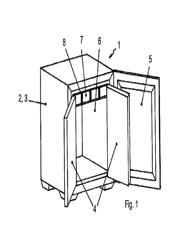
Fig. 1 shows a cuboid transport container 1 whose container
wall arrangement surrounds an interior chamber on all sides
except for an opening. The container wall arrangement
includes two side walls, a back wall, a bottom and a
ceiling.
CA 03203681 2023- 6- 28
22
The container wall arrangement consists of a multilayer
insulation 2 and 3, an inner double door 4, an outer door
5, an energy distribution layer 6 forming the inner shell,
drawers 7 with dry ice and a drawer guide 8, which are
attached to the energy distribution layer 6 of the ceiling.
As can be seen in the sectional view according to Fig. 2,
the insulation consists of an outer, first insulation layer
2 and an inner, second insulation layer 3. The first
insulation layer is, for example, 60-80 mm thick and
consists of a multilayer structure of honeycomb deep-drawn
PET foils coated on both sides with aluminum. As a result,
an insulating performance of the first insulation layer of
4 to 300 mW/(m.K) is achieved. The second insulation layer
3 is 30-50 mm thick and consists of a high-performance
insulation, such as vacuum insulation panels (VIP) or
aerogel, achieving an insulation performance of 1 to 30
mW/(m.K).
In the area of the front opening of the transport
container, the inner double door 4 can be attributed to the
inner, second insulation layer 3 and the outer door 5 to
the outer, first insulation layer 2. As shown in Fig. 3,
the inner double door 4 consists in each case of an inner
13 and an outer aluminum half-shell 14, with the inner and
outer shells being thermally decoupled. Decoupling is
achieved with inner insulation 3 consisting of 30-50 mm
thick high-performance insulation, such as vacuum panels,
and connecting elements made of low-heat conducting, cold-
resistant plastic 12 (e.g. PEEK). The outer door 5 is
insulated with a 60-80 mm thick multi-layered structure of
honeycomb deep-drawn PET foils coated on both sides with
aluminum. The combination of high insulation performance of
CA 03203681 2023- 6- 28
23
the inner double door 4 (1 to 30 mW/(m.K)) and medium
insulation performance of the outer door 5 (4 to 300
mW/(m.K)) results in a temperature of around 0 C (between -
20 C and 8 C) on the outside of the inner double door 4 at
a temperature of teh interior chamber of -60 C to -80 C.
This makes it possible to open the inner double door 4
manually (without risk of cold burn) during operation.
At the edge of the inner door 4 there is a seal 11 which
allows the CO2 gas produced to escape, but at the same time
largely prevents warm ambient air from flowing in. Seals 10
are also located on the outer door so that, together with
the inner door seal 11, a labyrinth is created which, on
the one hand, allows the CO2 gas produced to escape and, on
the other hand, ensures that the moisture of incoming air
condenses on the outside of the inner double door 4, which
has a temperature around 0 C (between -20 C and 8 C). This
prevents the penetration of humidity into the interior
chamber and the associated formation of ice.
The energy distribution layer 6 consists of e.g. 0.5-5 mm
thick aluminum plates. These have a thermal conductivity of
about 150 W/(m.K), which distributes local heat inputs
across the interior envelope and creates a uniform
temperature distribution in the interior chamber. The
joints of the individual aluminum plates on the sides and
corners are reinforced with rivets so that they can
withstand the forces generated by thermal stresses.
The drawers 7 as well as the drawer guides 8, which are
attached to the upper side of the inner shell 6, are also
made of 0.5-5 mm thick aluminum plates with a thermal
CA 03203681 2023 6 28
24
conductivity of 150 W/(m.K). The dry ice 9 is introduced
directly into the drawers.
Figs. 4 and 5 show a modified version, where in Fig. 5 the
left half is a front view of the transport container with
the inner double door 4 closed and the outer door 5 open,
and the right half shows a cross-section through the
transport container with drawers. In the modified version
shown here, the inner double door 4 is made smaller so that
the drawers 7 can be opened when the inner double door 4 is
closed. In addition, the outside of the dry ice drawers 7
is insulated by 30-50 mm thick vacuum panels 17. This has
the advantage that the running time of the transport
container can be extended as required by renewing the dry
ice. In this case, the inner double door does not have to
be opened and the transported goods do not have to be taken
out.
Furthermore, in this variant, the insulation of the outer
door 5 is improved by inserting additional vacuum panels 16
or partially replacing the existing insulation 15 with
vacuum panels. This reduces the heat input through the
front door and therefore has a beneficial effect on the
running time of the transport container.
CA 03203681 2023- 6- 28