Note: Descriptions are shown in the official language in which they were submitted.
WO 2022/159693
PCT/US2022/013300
Title: VENTED DUAL PORT CENTRIFUGE TUBE
FIELD OF THE INVENTION
This invention relates to a vented dual port centrifuge tube used to
effectively
separate and concentrate fluid biological products such as blood, stem cells,
bone marrow
aspirate and the like into constituent components, which may be conveniently
and
efficiently aspirated following centrifugation. The apparatus is particularly
effective for
sequestering platelet rich plasma and bone marrow aspirate for use in
surgical, medical
and veterinary procedures.
BACKGROUND OF THE INVENTION
Platelet-rich blood plasma is required for use in various medical procedures.
This
blood product is particularly effective due to its growth promoting features,
which assist
greatly in wound healing and bone regeneration. Presently, blood plasma with a
high
concentration of platelets is utilized for dental implants and other
periodontal procedures,
facial reconstruction, oral or maxillofacial surgery and chronic wound care In
order to
obtain a required concentration of platelets, a blood sample normally must be
centrifuged
in order to separate the blood into its component blood products (i.e.,
plasma, red blood
cells and platelets). The platelets, typically in a form of a white "buffy
coat", are then
separated from the blood sample and sequestered in concentrated form through
aspiration. Conventional aspiration techniques often fail to provide a
satisfactory
concentration of platelets. Cross-contamination between the constituent
products is
frequently encountered In recent years there has been an increasing demand for
improved, cost effective and easy to operate centrifuge tubes that facilitate
the
CA 03203699 2023- 6- 28
WO 2022/159693
PCT/US2022/013300
sequestration of platelets and provide for highly pure platelet production,
while minimizing
cross-contamination between blood components.
I have developed various centrifuge assemblies as disclosed in United States
Patent Nos. 6,835,353, 7,976,796, 10,300,481 and 10,537,888 to address the
foregoing
needs and concerns. These products have achieved superior results and proven
to
constitute a significant improvement over the prior art. I have also developed
a dual piston
centrifuge tube as disclosed in US Patent No. 10,987,672. This product
especially reduces
the risk of cross contamination of sequestered PRP by air and other blood
components
present in the tube. My dual piston device employs a simple and failure-
resistant
construction that enables PRP and other constituents of fluid biological
products to be
obtained in a quick, convenient and reliable manner for use in various
surgical, medical
and veterinary applications.
Notwithstanding the improved results achieved by the foregoing products, an
ongoing need continues to exist for improved centrifuge tubes of this type In
particular, it
is desirable to employ a construction that is constructed as simply as
possible in order to
reduce manufacturing complexity and the potential for product failure. In
addition, the user
should be able to operate the tube more conveniently and smoothly, and wfthout
encountering undue sticking or resistance caused by pressure imbalances
produced in
the tube during the sequestration process. This will better enable users to
obtain high
quality PRP, bone marrow aspirate and other desired biological constituents,
SUMMARY OF THE INVENTION
It is therefore an object of the present invention to provide a simple,
efficient and
highly reliable centrifuge tube that allows blood, bone marrow aspirate and
other fluid
biological products to be effectively sequestered and concentrated into
constituent
components and conveniently aspirated following separation.
It is a further object of this invention to provide a dual port centrifuge
tube featuring
a simpler and less costly construction, and which is easier to use and less
prone to product
failure than existing centrifuge tubes.
It is a further object of this invention to provide a dual port centrifuge
tube that is
effectively, resists cross-contamination and yields a high quality biological
fluid aspirate.
2
CA 03203699 2023- 6- 28
WO 2022/159693
PCT/US2022/013300
It is a further object of this invention to provide a vented dual port
centrifuge tube
employing a single piston and unique, highly efficient vent pipe construction
that effectively
equalizes air pressure imbalances in the tube and enables the piston to
exhibit a smoother
resistance-free movement, which facilitates and improves usage of the tube.
it is a further object of this invention to provide a dual port centrifuge
tube which
enables the manufacture of improved, highly concentrated and pure PRP in a
relatively
uncomplicated, quick, efficient, safe and effective manner.
It is a further object of this invention to provide a dual port centrifuge
tube that
enables blood product and other fluid biological products to be aspirated in a
reliable and
extremely safe manner.
It is a further object of this invention to provide a vented dual port
centrifuge tube
that permits a host of chemicals, bodily fluids, and other fluid biological
products to be
separated and individually aspirated with a low risk of cross contamination or
airborne
contamination.
It is a further object of this invention to provide a dual port centrifuge
tube that is
particularly effective for sequestering a high concentration of platelet-rich
plasma for use
in various medical, surgical arid veterinary procedures.
It is a further object of this invention to provide a dual port centrifuge
tube that may
be used effectively and efficiently for separating and aspirating a wide range
of biological
products, including but limited to blood, stem cells, bone marrow aspirate,
etc.
It is a further object of this invention to provide a uniquely vented
centrifuge tube
that eliminates the unbalanced operation commonly exhibited by known
centrifuge tubes
during centrifugation by reducing the amount of air trapped in the tube.
It is a further object of this invention to provide a dual port centrifuge
tube featuring
a configuration and construction that enables PRP and other biological fluids
to be more
effectively and completely recovered from the tube following centrifugation.
This invention results from a realization that a centrifuge tube for
separating and
aspirating constituent components of a fluid biological product may be
significantly and
efficiently simplified and yet provide extremely effective results by
employing two opposing
common inlet and outlet ports at respective ends of the tube, a single piston
or diaphragm
that is slidable through the tube and a unique flexible vent pipe
interconnected between a
3
CA 03203699 2023- 6- 28
WO 2022/159693
PCT/US2022/013300
capped upper end of the tube and the piston. When such a centrifuge tube is
operated in
accordance with this invention, it effectively equalizes or neutralizes
pressure within the
tube during injection and aspiration steps and therefore allows the user to
perform such
steps smoothly, easily and with less resistance or sticking exhibited by the
piston. At the
same time, the tube is constructed to produce a concentrated and high quality
aspirate
that may be employed in various surgical, medical and veterinary applications.
This invention features a dual port centrifuge tube assembly that includes an
elongate tubular receptacle having an interior chamber and closed upper and
lower
portions. A liquid impermeable piston is mounted within the chamber and is
slidable
through the chamber while maintaining sealing engagement with an interior
surface of the
receptacle. A first common inlet and outlet port is formed in the upper
portion of the
receptacle for communicating with an upper region of the interior chamber
above the
piston. A second common inlet and outlet port is formed through the lower
portion of the
tubular receptacle for communicating with a lower region of the interior
chamber below the
piston. A vent is formed through the upper portion of the receptacle and a
flexible vent
pipe is communicably interconnected between the vent and the piston in
communication
with the lower region of the chamber.
In a preferred embodiment, the upper portion of the tubular receptacle
includes an
upper cap through which the vent and the first common inlet and outlet port
extend. The
vent is preferably spaced apart and distinct from the first common inlet and
outlet port. The
lower portion of the tubular receptacle may include a substantially fiat base
through which
the second common inlet and outlet port is formed to communicate with the
lower region
of the chamber. The first common inlet and outlet port communicates with the
upper region
of the chamber above the piston.
The piston may include a body that is sealably and slidably interengaged with
the
interior sidewall of the tubular receptacle. A passageway may extend
vertically through the
piston body. The passageway, which is preferably formed centrally through the
piston
body, may be communicably interconnected between the vent pipe and the lower
region
of the receptacle chamber. The piston body may further include upper and lower
circumferential flanges that are attached to and extend upwardly and
downwardly
4
CA 03203699 2023- 6- 28
WO 2022/159693
PCT/US2022/013300
respectively from the piston body. The lower circumferential flange will have
a diametric
channel formed therein.
The second common inlet and outlet port may include a tubular stem that
extends
into the lower region of the chamber. The stem may include an elbow having a
distal end
disposed proximate the circumferential flange of the piston and proximate an
interior
surface of a sidewall of the receptacle.
A base may be attached to and depend from the lower portion of the tubular
receptacle. Preferably, the base has a cylindrical shape that conforms to the
shape and
diameter of the tubular receptacle. The base supports the tubular receptacle
above an
underlying surface and the second common inlet and outlet port may be
surrounded by
and centrally disposed within the base.
In the preferred version of the tube, blood or other biological fluid is
introduced into
the upper chamber region of the tubular receptacle through the first common
inlet and
outlet port. This drives the piston downwardly through the receptacle such
that air in the
lower region of the chamber beneath the piston is pushed upwardly through the
passageway of the piston body and through the vent tube. Such air is expelled
through
the vent in the top of the tube, which equalizes pressure in the tube. When
the piston is
fully lowered, the diametric channel receives the tubular stem of the second
port. The
tubular receptacle is then centrifuged a first time to separate the biological
fluid into a pair
of layers representing respective constituent components (e.g., red blood
cells ¨ RBC,
and plasma platelet suspension - PPS). The user then aspirates the top
sequestered fluid
layer (e.g., PPS) through the first common inlet and outlet port. That
aspirated constituent
is then introduced through the second common inlet and outlet port in the
lower end of the
receptacle to occupy a lower region of the receptacle chamber. Again, air
within the lower
region is displaced through the vent tube and vent to equalize pressure within
the tube.
The receptacle is then centrifuged a second time to separate the fluid
constituents into the
respective layers within the lower chamber region. In cases where PPS has been
introduced into the lower chamber region, the second centrifugation may
produce an
upper layer of platelet poor plasma (PPP) and a lower huffy coat layer
comprising PPS
and platelet rich plasma PRP. Most of the upper layer produced within the
lower chamber
region is then aspirated to leave a remaining fluid within the tower region.
The tube is then
CA 03203699 2023- 6- 28
WO 2022/159693
PCT/US2022/013300
agitated to mix the remaining fluid (e.g., to mix any remaining PPP with buffy
coat). This
mixed product is then aspirated, which, in the case of blood sequestration,
yields a high
quality PRP product_
In an alternative embodiment, the second common inlet and outlet port may be
offset from the center of the closed lower portion of the tubular receptacle.
In such
embodiments, a semi-cylindrical base is attached to and depends from the lower
end
portion of the tubular receptacle such that the second common inlet and outlet
port is
positioned radially to be at least partially outside of the semi-cylindrical
base. This provides
syringe access to the second common inlet and outlet port when the centrifuge
tube is
used as described below.
In the alternative embodiment of the invention, the second common inlet and
outlet
port may include a tubular channel that extends into the interior chamber of
the receptacle
below the piston. The channel may have a diagonal or slanted upper end to
facilitate
aspiration of PRP or other constituent fluids from the receptacle. The semi-
cylindrical base
may include a longitudinal slot formed in the base to facilitate user access
to the second
common inlet and outlet port.
6
CA 03203699 2023- 6- 28
WO 2022/159693
PCT/US2022/013300
BRIEF DESCRIPTION OF THE DRAWINGS
Other objects, features and advantages will occur from the following
description of
a preferred embodiment and the accompanying drawings, in which:
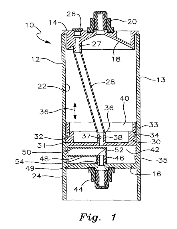
FIG. 1 is an elevational and cross-sectional front view of a preferred vented
dual
port centrifuge tube in accordance with this invention;
FIG. 2 is a simplified elevational side view of the tube of FIG. 1;
FIG. 3 is a simplified elevational rear view of the preferred tube with a
biological
fluid, such as a blood sample, being introduced into the receptacle chamber
above the
piston;
FIG. 4 is a view similar to FIG. 3, which shows the tube after it is
centrifuged a first
time to separate the biological fluid into first and second constituent
components, e.g, red
blood cells and platelet plasma suspension (PPS);
FIG 5 is a similar elevational view of the preferred tube wherein one of the
separated constituents, e g , PPS, is aspirated from the receptacle through
the first
common inlet and outlet port to raise the piston within the tubular
receptacle;
FIG. 6 is a similar elevational view of the preferred tube that depicts the
introduction
of the previously aspirated component through the second common inlet and
outlet port
into a lower region of the receptacle chamber below the piston;
FIG 7 is a similar elevational rear view of the preferred tube after it
undergoes a
second centrifugation to separate the constituent component in the lower
chamber region
into third and fourth constituent components, e.g., platelet poor plasma (PPP)
and platelet
rich buffy coat (PRB);
FIG. B is an elevational view of the tube similar to that shown in FIGS, 3-7
and
which depicts the third constituent component being aspirated from the
receptacle through
the second common inlet and outlet port;
FIG. 9 is a similar elevational view that depicts agitation of the tube to mix
the third
and fourth constituent components remaining in the receptacle to form a final
fluid
constituent product to be recovered, e.g., platelet rich plasma (PRP);
FIG. 10 is a view of the tube similar to that shown in FIGS. 3-9, whin depicts
the
tube horizontally orientated for aspiration of PRP remaining in the
receptacle;
CA 03203699 2023- 6- 28
WO 2022/159693
PCT/US2022/013300
FIG. Ills an elevational front view of an alternative centrifuge tube in
accordance
with this invention with a blood sample received in the chamber of the tubular
receptacle
above the piston,
FIG. 12 is a similar view of the alternative tube after it has been
centrifuged a first
time to separate the blood sample into red blood cells and PPS;
FIG. 13 is a vievv similar to FIGS. 11 and 12 that depicts the tube after the
PPS has
been aspirated from the receptacle and with the piston elevated and red blood
cells being
constrained within the upper chamber region of the receptacle above the
piston;
FIG. 14 is a view similar to FIGS, 11-13 and further depicting PPS being
introduced
into the lower region of the receptacle chamber beneath the piston;
FIG. 15 is a view similar to FIGS, 11-14 after the tube has undergone a second
centrifugation to separate the PPS into an upper layer of PPP and a lower
layer of PRB;
FIG. 16 is a similar view of the alternative tube with the PPP drawn down to a
level
such that the total fluid remaining in the lower region of the receptacle
chamber is less
than 7 ml.; and
FIG. 17 is a similar view of the alternative tube after the remaining fluid
components
in the lower region of the receptacle chamber (e.g., PPP and PRB) have been
mixed to
produce a high quality PRP that is aspirated from the receptacle through the
second
common inlet and outlet port.
8
CA 03203699 2023- 6- 28
WO 2022/159693
PCT/US2022/013300
DETAILED DESCRIPTION OF PREFERRED EMBODIMENTS
There is shown in FIGS. 1-2 a vented dual port centrifuge tube 10 that
includes a
tubular or cylindrical receptacle 12. The receptacle is defined by an elongate
cylindrical
sidewall 13 that extends between closed upper and lower end portions. The
closed upper
end portion comprises a cap 14 (FIG. 1) that may be either permanently or
removably
attached to sidewall 13. The lower end portion includes a generally planar
floor 16 that is
unitarily connected to sidewall 13 and extends across the bottom of the
receptacle. As
best depicted in FIG. 1, cap 14 preferably includes an interior opening 18
that has a
generally truncated conical shape and communicates with a first common inlet
and outlet
port 20 to facilitate introduction and aspiration of biological fluids into
and out of receptacle
12, as described more fully below. It should be noted that in certain
embodiments, the
configuration of the cap and cap opening may be simplified or otherwise
modified. Indeed,
in FIGS. 2-10, a simpler and generally planar cap 14a is disclosed. In such
cases the port
20 may be communicably connected to the interior of receptacle 12 through a
straight or
otherwise alternatively shaped opening. It should be understood that in all
versions of this
invention, the cap or other upper end of tubular receptacle has an opening or
passageway
that defines or communicates with a syringe-engaging common inlet and outlet
port for
introducing and aspirating biological fluids into and out of the tubular
receptacle 12 in
accordance with this invention Nonetheless, the particular configuration and
construction
of the upper end cap may be varied within the scope of this invention.
Receptacle 12 includes an interior chamber 22 that extends from floor 16 to
cap
14. This chamber accommodates blood, chemicals, stern cells, bone marrow
aspirate or
other biological fluids/products to be centrifuged and aspirated using tube 10
the tube is
particularly effective for sequestering and recovering high quality platelet
rich plasma
(PRP). Nonetheless, it may be employed effectively for separating and
recovering various
other fluid biological constituents within the scope of this invention.
As used herein "centrifuge" and 'tube" should be understood to comprise
assorted
shapes and sizes of vessels, receptacles and containers having an interior
chamber for
holding a biological product and capable of being centrifuged to aspirate the
product into
constituent components, The vented dual port, single piston centrifuge tube
disclosed
9
CA 03203699 2023- 6- 28
WO 2022/159693
PCT/US2022/013300
herein is not limited to just tubular and elongate configurations, although
such
configurations will typically be used in preferred embodiments of this
invention.
A cylindrical skirt 24 is connected unitarily with and depends from floor 16
and/or
sidewall 13 of tubular receptacle 12. In alternative embodiments, skirt 24 may
be separate
from and releasably attached or affixed to the lower end of receptacle 12. The
cylindrical
skirt acts as a base, which stably supports the tubular receptacle in an
upright condition
on a table or other flat or horizontal surface. In this way, the centrifuge
tube does not
require a separate rack or holder for support, Cylindrical skirt 24 also
securely supports
the device upright in a standard centrifuge machine when the tube is
centrifuged in
accordance with the orientation depicted in FIGS. 4 and 7 as described more
fully below.
Tubular receptacle 12 is typically composed of a durable plastic material such
as
polypropylene or other material suitable for medical or veterinary
applications. The tube
should be constructed to withstand the forces exerted by centrifuging. In
certain
applications, shatter-resistant glass may be employed.
A plurality of graduated volume markings, not shown herein, but see US Patent
No.
7,976,796 (hereinafter '796), may be formed at various selected intervals
along the
exterior sidewall 13 of tubular receptacle 12. Such markings should be made at
heights or
intervals corresponding to commonly selected volumes of biological product
that will be
introduced into the tube. Such markings may be varied within the scope of This
invention.
A vent 26 is formed through cap 14, 14a to communicably interconnect chamber
22 with the ambient air surrounding tube 10. Vent 26 may be constructed
analogously to
the vents disclosed in Patent No. '796 and US Patent No. 10,300,481
(hereinafter '481).
In particular, vent 26 may comprise a vent plug that fits through a hole in
the cap. The vent
is communicably connected with an elongate, flexible vent pipe 28 in order to
equalize and
neutralize pressure in receptacle 12 during the operation of tube 10 as
described below.
Vent 26 may feature a through channel that accommodates a filter for trapping
contaminants that are pulled into receptacle 12 with the ambient air during
operation of
the tube, again as described below. Once again, this filter construction may
be of the type
disclosed in the above-referenced patents. Vent pipe 28 is composed of a
flexible yet
strong plastic material such as silicone that permits the pipe to be reliably
flexed or
collapsed during operation of tube 10.
CA 03203699 2023- 6- 28
WO 2022/159693
PCT/US2022/013300
In preferred versions of this invention, cap 14, 14a is permanently secured to
the
tubular receptacle. This may be accomplished by ultrasonic welding or other
known
methods. The upper end of the receptacle may also be formed by a cap or lid
that is
molded or otherwise formed unitarily with the cylindrical receptacle using
techniques
known to persons skilled in the art. Alternatively, the end cap may be
releasably engaged
with an open upper end of receptacle 12 in the manner for example shown in US
Patent
Nos. '481 and 10,987,672 (hereinafter '672). The cap may have a partially
recessed upper
surface as shown in FIG. 1, or a flat upper surface as depicted in the
remaining figures.
The truncated conical inlet 18 shown in FIGS. 1 arid 2 operates analogously to
the
corresponding opening or channel depicted in US Patent No. '481 to facilitate
introduction
and aspiration of biological fluids into and out of the receptacle so that
constituent
components can be separated using the tube.
Vent 26 supports a tubular stern 27, FIG. 1, that is itself communicably
interengageel with an upper end of flexible vent pipe 28. The opposite lower
end 36 of pipe
28 is communicably connected to a tubular fitting 38 that extends generally
centrally
through a liquid impermeable piston 30, which piston is itself mounted for
slidable
reciprocating movement within chamber 22 of receptacle 12. As described more
fully
below, this provides for a wholly unique and particularly effective manner for
equalizing or
neutralizing pressure within tube 10 during the centrifugation and fluid
separation process.
As previously indicated, first common inlet/outlet port 20 is formed in an
upper
portion of receptacle 12, preferably through cap 14, 14a. It should be
understood that in
alternative embodiments the first common inlet and outlet port may be formed
elsewhere
in the upper portion of the receptacle above piston 30. More particularly
first upper
inlet/outlet port may comprise a conventional self-sealing construction and
employ a
standard luer port for releasably and securely interconnecting a hypodermic
syringe to the
port. Various forms of construction that may be used for the upper end cap 14
and the first
common inlet/outlet port 28 are disclosed, for example, in US Patent No.
6,835,353
(hereinafter Patent No. '353), Pat. Nos. '481, '796 and '672, the disclosures
of which are
incorporated herein by reference. Preferably, caps 14, 14a are composed of
polypropylene or other material similar to that formed in the tubular
receptacle itself. The
11
CA 03203699 2023- 6- 28
WO 2022/159693
PCT/US2022/013300
common inlet/outlet port may be communicably attached to the caps or
alternatively
molded together with the cap in a single manufacturing process.
As shown in FIGS. 1 and 2, piston 30 has a generally cylindrical peripheral
shape
conforming to the interior shape of sidewall 13. The piston includes a body
31, FIG.1,
having upper and lower peripheral flanges 33 and 35 extending respectively
upwardly and
downwardly therefrom. Body 31 includes an annular peripheral groove 32, best
shown in
FIG. 2, that accommodates an 0-ring or alternative seal 34, which sealingly
and slidably
interengages the interior surface of sidewall 13 Of tubular receptacle 12.
This allows piston
30 to move longitudinally through chamber 22 during operation of tube 10, as
indicated by
double headed arrow 36 in FIG. 1. Vent pipe 28 extends through an open upper
compartment of piston 30 surrounded by flange 33 and the lower distal end 36
of pipe 28
communicably engages tubular fitting 38. This fitting is formed centrally and
communicably
through piston body 31 and features an air passageway 37 that interconnects
pipe 28 to
an open lower piston compartment 42 surrounded by flange 35. In this manner,
the vent
pipe 28 and interconnected vent 26 are communicably interconnected through
open lower
piston compartment 42 to a lower region of receptacle chamber 22 disposed
beneath
piston 30. This provides a unique and very effective means to vent and
neutralize pressure
in the lower region of chamber 22 during operation of tube 10 as described
more fully
below. As best shown in FIG. 2, a channel 43 is formed diametrically across
lower
compartment 42 of piston 30.
A lower, second common inlet and outlet port 44 is operatively and
communicably
connected to a lower region of chamber 22 beneath piston 30. In particular,
inlet/outlet
port 44 includes a tubular conduit or stem section 46 that is formed through
floor 16 of
receptacle 12 and extends longitudinally into interior chamber 22. Second
inlet/outlet port
44 again includes a self-sealing valve port and luer-type interconnection
analogous to
previously described first port 20. Port 44 is attached to the exterior
surface of receptacle
floor 16 within skirt 24 and is communicatively connected through floor 16 to
conduit 46,
which extends upwardly from the floor of the receptacle. In alternative
embodiments,
conduit 46 may be formed separately from and connected to floor 16. In still
other
embodiments, conduit 46 may comprise an integral and unitary part of port 44.
Conduit 46
itself is communicably joined to a tubular elbow 48. As best shown in FIG. 1,
the proximal
12
CA 03203699 2023- 6- 28
WO 2022/159693
PCT/US2022/013300
end of elbow 48 interengages floor 16. The distal end of elbow 48 is
positioned proximate
the interior sidewall surface of the receptacle chamber 22. Elbow includes a
generally
vertical portion 52 and a horizontal portion 54. As best shown in in FIG. 2,
channel 43
formed diametrically through lower compartment 42 of piston 30 is generally
aligned with
the horizontal portion 54 of tubular elbow 48. Accordingly, when piston 30 is
in an elevated
condition as shown in FIG. 2, the piston 30 and diametric channel 43 are
raised above
and clear of elbow 48. When the piston is lowered within chamber 22, as shown
in FIG. 1,
tubular elbow 48 fits neatly within channel 43 of piston 30. This occurs
during use and
operation of tube 10 as described more fully below. Otherwise, the exterior
connective
portion of second common inlet and outlet port 44 supported below floor 16 is
constructed
and operates analogously to standard luer-type ports as referred to above and
in the
patents and applications referenced herein.
Prior to usage of tube 10, sealing piston 30 is typically elevated at least
somewhat
within chamber 22 of receptacle 12, although in some cases it may be in the
lowered
condition shown in FIG. 1. Tube 10 is utilized to centrifuge a fluid
biological product into
its constituent components and then to aspirate one ore more of those
components as
shown in FIGS. 3-10. A preferred representative use for tube 10 is in the
separation of a
blood sample into constituent blood components. Typically, it is desirable to
separate
plasma and ultimately platelets, from red blood cells of a blood product in
order to derive
a highly concentrated platelet rich plasma (PRP) for use in various surgical,
medical or
veterinary applications. This process is performed using assembly 10 in the
following
manner.
Initially, the empty receptacle 12 is stood upright on its cylindrical base or
skirt 24
upon an underlying table or platform. If a separate cover or closure is
engaged with tube
or either of its ports 20, 44, the cover/closure is removed. Blood product B,
FIG. 3, is
then introduced into the interior chamber 22 of receptacle 12. Specifically,
for example, a
60m1 or other sized hypodermic syringe containing the blood or other
biological product is
operably engaged with the first or upper self-sealing port 20 in a standard
manner, See
Patent Nos. '353, '796 and '481. The luer port 20 holds the dispensing tip of
the syringe in
place so that the hypodermic syringe is securely engaged with tube 10. The
syringe is
then operated in a conventional manner to introduce blood product B to be
separated
13
CA 03203699 2023- 6- 28
WO 2022/159693
PCT/US2022/013300
through port 20 and into interior chamber 22 of receptacle 12, FIG. 3. As
blood is
introduced into upper region 60 of chamber 22, the increasing volume of blood
pushes
piston 30 downwardly through receptacle 12, as indicated by arrows 62. Blood
product is
added to the receptacle by the syringe in this manner until a selected level
of fluid is
injected/introduced into the receptacle. Typically, piston 30 is pushed until
it engages or is
proximate to floor 16 of receptacle 12. As previously described, tubular elbow
48 is
enclosed by the descending piston 30 and specifically received in channel 43
(See FIGS.
1 and 2). Critically, as piston 30 is driven downwardly through the
receptacle, flexible vent
pipe 28 expands from the coiled or collapsed condition shown in FIG. 2 to the
open and
extended condition show in FIG. a. As a result, the increased air pressure
generated by
piston 30 within the region of chamber 22 below piston 30 is effectively
vented from the
tube through pipe 28 and vent 26. Air pressure within tube 10 is effectively
neutralized or
equalized so that a smooth and stick/resistance-free operation is achieved.
Finally, when
a selected or desired volume of blood has been added to the receptacle,
injection is
stopped and the injecting syringe is disengaged from port 20. For human
bloodvvork, the
selected volume of blood may be, for example, 50-60 nrils. This volume is
preferred
because it typically yields approximately 7 mls of platelet rich plasma after
the process is
completed.
Tubular receptacle 12 is next placed in a centrifuge and counterbalanced by
another tube placed in the centrifuge machine. Skirt 24 allows tube 10 to sit
stably within
the centrifuge. This helps the tube to remain properly balanced while it is
being centrifuged.
The tube is centrifuged for approximately 90 seconds (although this time as
well as the
speed of the centrifuge may be varied within the scope of this invention in a
manner known
to persons skilled in the art) and, as shown in FIG. 4, blood B is thereby
separated within
upper chamber region 60 into a top layer comprising largely platelet/plasma
suspension
(PPS) and a bottom layer (RBC) comprising primarily red blood cells. At this
stage,
typically at least 90% of the red blood cells in the blood product are
separated from layer
PPS and settle within layer RBC. Various known types of centrifuge machines
may be
employed for the initial centrifuging. A single round or multiple rounds of
centrifuging may
be utilized at this stage. After the first centrifuging stage is completed,
tube 10 is removed
14
CA 03203699 2023- 6- 28
WO 2022/159693
PCT/US2022/013300
from the centrifuge and again supported on its flat base or skirt 24. Both
layers PPS and
RBC are held securely in the upper space 60 of chamber 22 above piston 30.
A new syringe is next engaged with port 20 and operated as represented by
arrow
66 in FIG. 5 to aspirate the PPS from upper space 60 of chamber 22. As
indicated by
arrow 70, this draws ambient air inwardly through vent 24 and vent pipe 28
into lower
region 72 of chamber 22 beneath rising piston 30. This effectively counteracts
and
neutralizes the vacuum being drawn in lower chamber region 22 as the piston is
pulled
upwardly in response to the aspiration of PPS. Once again, pressure is
equalized within
the tube and there is much less potential for sticking of the piston and
resistance to
aspiration of the PPS. The aspiration operation is therefore smoother and
facilitated.
Aspiration continues in this manner until piston 30 generally reaches the
boundary
between the PPS and RBC layers. Aspiration is then discontinued and the
aspiration
syringe is disengaged from port 20. The red blood cells RBC remain segregated
and
constrained in diminished space 60 between piston 30 and cap 14.
The syringe holding the retrieved PPS is next engaged with second common
inlet/outlet port 44 within skirt 24 according to FIG. 6. The syringe is
operated to inject the
sequestered PPS as indicated by arrow 74 through lower port 44 and connected
elbow
48 into lower region 72 of chamber 22. This substantially fills lower chamber
region 72
with the retrieved PPS component.
When all of the PPS is reinjected into the lower chamber region 72 of
receptacle
12, the PPS syringe is disengaged from second inlet/outlet port 44 and
receptacle 12 is
again placed in a centrifuge machine. The tube is then further centrifuged for
approximately 5 minutes, although this time may again be varied within the
scope of the
invention. For both centrifuging steps, centrifuge speeds and times may be
adjusted in a
manner that will be understood to those skilled in the art. As reflected in
FIG. 7, the PPS
injected into chamber region 72 is separated by the second centrifuging
operation into an
upper layer of platelet poor plasma (PPP) and a lower layer of platelet rich
buffy coat
(PRB). Tubular elbow 48 is constructed and positioned such that its distal end
or tip 50 is
held above the PRB layer and within the PPP layer.
As represented in FIG. 8, a new syringe is interengaged with second common
inlet/outlet port 44 and operated, as indicated by arrow 76, to aspirate PPP
fluid from lower
CA 03203699 2023- 6- 28
WO 2022/159693
PCT/US2022/013300
region 72 of chamber 22. Typically, the syringe is aspirated from receptacle
12 until a total
of approximately 7 ml of fluid, consisting of 6 ml PPP and 1 ml PRB remains in
chamber
22 below piston 30 These are typically the amounts remaining when an initial
blood
product volume of 50-60 mls is subjected to the two-stage centrifugation
process in tube
as described above. Respective volumes may vary somewhat within the scope of
this
invention. As PPP is aspirated from tubular receptacle 12, ambient air is
again drawn into
the chamber through vent 26 and vent pipe 28 in the manner indicated by arrows
80. This
again neutralizes pressure within lower region 72 of chamber 22 which
facilitates
aspiration of the PPP.
The syringe containing the aspirated PPP is next disengaged from port 44. The
platelets in the (e.g., 1 mi) platelet rich buffy coat layer PRB are then
resuspended in the
remaining (e.g., 6 ml) PPP layer contained in receptacle 12. This is typically
accomplished
as shown in FIG. 9 by swirling or otherwise gently agitating the tubular
receptacle 12, as
shown by double-headed arrows 82, so that the platelets of fluid layer PRB are
effectively
re-suspended into layer PPP. This produces a resulting volume of approximately
7 ml of
pure and concentrated platelet rich plasma (PRP).
Following re-suspension of the buffy coat in the platelet poor plasma to
produce
the desired PRP, receptacle 12 is oriented horizontally in the manner shown in
FIG. 10.
This positions supportive skirt 24 and second inlet/outlet port 44 such that
tubular elbow
48 is oriented with its distal end or tip 50 positioned within the PRP
collected against the
now lower interior surface of sidewall 13 of receptacle 12. The user
operatively connects
a new syringe to the lower pod 44 and aspirates the PRP, as indicated by arrow
88,
through port 44 via tubular elbow 48. By positioning tip 50 of tubular elbow
48 very close
to the interior surface of the sidewall 13, virtually all of the PRP
(approximately 7 rills)
contained in the receptacle can be aspirated from receptacle 12. This PRP has
an
extremely high platelet concentration and purity (approximately 80% or more).
The
aspirated PRP may then be utilized effectively for desired surgical, medical
and veterinary
applications. During the final aspiration step, the operation of the syringe
is again facilitated
because as PRP is withdrawn through elbow 48 and port 44, ambient air is
introduced into
region 72 of chamber 22 through vent 26, interconnected vent pipe 28 and
tubular fitting
38 (FIG. 1) formed through piston 30. The pressure within the tube remains
effectively
16
CA 03203699 2023- 6- 28
WO 2022/159693
PCT/US2022/013300
equalized and neutralized. Resistance to movement of piston 30 is reduced and
aspiration
is facilitated.
An alternative vented dual port, single piston centrifuge tube 110 according
to this
invention is shown in FIGS. 11-17. The capacity, materials composing the tube
and many
if not most of the components comprising the tube are identical or analogous
to those
employed in the previously described embodiment. The most significant
differences are
described below.
Tube 110 includes a receptacle 112 featuring an upper portion that includes a
cap
114 sealed or otherwise attached to an upper end of a cylindrical sidewall
113. Cap 114
supports a first, upper inlet and outlet port 120 and a vent 126. A vent pipe
128 is
communicably connected to vent 126 in the manner previously described. Indeed,
cap
114, port 120, vent 126 and vent pipe 128 are constructed in the manner
previously
described
Receptacle 112 includes an interior chamber 122 that extends from cap 114 to a
floor 116 at the lower end of receptacle 112. Unlike the previously described
embodiment,
sidewall 113 of receptacle 112 includes an interior lip or ledge 115 above
floor 116 and
surrounding a smaller diameter lower portion 117 of chamber 122.
A second common inlet and outlet port 144 is mounted to floor 116. Port 144
again
includes exterior components 145 that feature a self -sealing luer port
connection, which
will be understood to persons skilled in the art. Port 144 further includes an
interior channel
148 that is communicably interconnected to luer port connection 145. Tubular
channel 148
is positioned within lower region 117 of receptacle chamber 122. The distal
tip 150 of
channel 148 is angled as shown in RGS. 12-15. This allows the tube 110 to
function in
the fluid sequestration process as described below.
A semi-cylindrical skirt 124, which forms a base of tube 110, is
interconnected to
and depends from the lower end of receptacle 112. In contrast to the
previously described
embodiment, lower common inlet and outlet port 144 is offset from the center
of the
receptacle floor and is interconnected to floor 116 proximate sidewall 113 and
at least
partially outside of an arcuate slot formed in skirt 124. Skirt 124 again
forms a base that
supports receptacle 112 in an upright condition as shown in FIGS. 12-18. This
provides
the user with unhindered access to pork 144 so that during use of tube 110, a
syringe may
17
CA 03203699 2023- 6- 28
WO 2022/159693
PCT/US2022/013300
be operably interconnected to port 145 for injecting fluids into and
aspirating fluids from
lower region 117 of chamber 122. This process is described more fully below.
Sequestration of biological fluids into constituent components and recovery of
such
components is performed using tube 110 in a manner analogous to that
previously
described for tube 10 in FIGS. 3-10. Once again, the process will be described
for the
recovery of high quality PRP from a blood sample. However, it should be
understood that
tube 110 may likewise be used to separate other biological fluids into
discrete constituent
components in an analogous fashion.
A liquid impermeable piston 130 is again slidably mounted within chamber 122
of
receptacle 112. The piston may have a construction identical or similar to
that of previously
described piston 30. In the version shown herein, the piston includes a
circumferential seal
or 0-ring 134 that interengages the interior surface of sidewall 13 such that
piston 130 is
able to slide longitudinally through chamber 122 while maintaining a seal
between the
upper and lower regions of the receptacle chamber. An air passageway fitting
138 is
formed centrally through the piston between upper and lower ends thereof. Air
passageway fitting 138 is communicably connected to a lower end of vent pipe
128. The
air passageway fitting may be joined unitarily to the vent pipe as depicted in
FIGS. 11-17.
Alternatively, the vent pipe and air passageway fitting may comprise two
separate pieces
(see FIG. 1) that are communicably joined by fitting one inside the other, for
example.
Other alternative means for communicably coupling the vent pipe and air
passageway
fitting (e.g., tubular couplers) are also encompassed by this invention. The
lower end of
fitting 138 communicates with a conical or tapered opening 139 of piston 30.
As a result,
vent 126 is communicably linked to the lower region 117 of chamber 122, i.e.,
the region
between the piston and floor 116 of receptacle 112.
As shown in FIG. 11, blood B is injected into the interior chamber of
receptacle 112
through first port 120. The introduced blood drives piston 130 downwardly
through
receptacle 112. Typically, an upper region of chamber 122 fills with blood and
piston 130
is pushed downwardly by the blood until the piston engages lip 115 of sidewall
113. This
limits downward movement of the piston and restricts further introduction of
blood into the
chamber. As piston 130 moves downwardly, air in the lower region of the
chamber is
vented to the atmosphere through opening 139 and air passageway fitting 138 in
piston
18
CA 03203699 2023- 6- 28
WO 2022/159693
PCT/US2022/013300
130, vent pipe 128 and vent 126. Pressure within the tube and particularly air
pressure in
the chamber region below piston 130 is equalized and the piston is operated by
the user
easily and without undue resistance or sticking within the receptacle. This
facilitates the
introduction of blood into tube 110 considerably.
After 50-60 mls or other volume of blood is introduced into the upper region
of
chamber 122 the syringe is removed from port 120 and tube 110 is placed in a
centrifuge
machine, which is operated for a predetermined time and at a selected speed to
separate
blood B into constituent components. Skirt 124 stably balances the tube as it
is
centrifuged. As shown in FIG. 12, the first centrifugation separates the blood
into a lower
level of red blood cells (RBC) and an upper level of plasma platelet
suspension (PPS). As
previously described and as further illustrated in FIG. 13, a new syringe is
attached to port
120 and aspirated to remove the PPS from tube 110. Vent pipe 128 collapses and
atmospheric air is permitted to enter the region of chamber 122 below piston
130. This
neutralizes pressure in the lower region of the chamber and facilitates
aspiration of the
PPS.
As depicted in FIG. 14, the PPS previously removed through port 120 is
reintroduced into tube 110 through the lower second port 144. In particular,
the syringe
containing the PPS is connected to exterior luer port connection 145 of port
144. The
syringe is operated to inject the PPS through luer connection 145 and channel
148 into
receptacle chamber 122 including narrower diameter lower region 117. Air
within the
region of the chamber between piston 130 and floor 116 is vented through the
open bottom
139 and air passageway fitting 138, as well as communicably connected vent
pipe 128
and vent 126. Pressure is thereby equalized within the chamber so that
injection of the
PPS is facilitated.
The PPS syringe is then disconnected from port 144 and tube 110 is centrifuged
again for a predetermined time and at a selected speed. This separates the PPS
in the
tower region of chamber 122 as shown in FIG. 15 Specifically, an upper layer
of PPP is
formed above a lower layer of PRB. At this point, the upper end of angled
channel 148 is
disposed within the PPP layer. The user attaches a new aspirating syringe to
port 144 and
aspirates PPP from tube 110, as indicated by arrow 190. Typically, the PPP is
drawn down
until approximately 7 ml of total fluid (PRB + PPP) remains in the chamber
between piston
CA 03203699 2023- 6- 28
WO 2022/159693
PCT/US2022/013300
130 and floor 116. See FIG. 16. Vent 126 and vent pipe 128 communicably
interconnect
the atmospheric/ambient air to the lower region of chamber 122 beneath piston
130. This
neutralizes pressure in the chamber and again facilitates aspiration of the
PPP from the
tube.
With approximately 7 ml of fluid remaining in the lower region of chamber 122,
the
tube is swirled or agitated as previously described, to mix the PPP and PRB
remaining in
the tube. This produces a high quality platelet rich plasma (PRP), as shown in
FIG. 17. A
new aspirating syringe is attached to lower second port 144. That syringe is
operated to
aspirate the PRP through channel 148 and self-sealing luer lock connection
145, as
indicated by arrow 192. The recovered PRP may then be used for required
medical and
veterinary purposes The unique vented construction employed by tube 110 again
facilitates the final aspiration of PRP.
It should be further understood that the vented dual port, single piston
centrifuge
tube of this invention may employ additional and alternative assorted features
and
components as depicted in the above-referenced devices shown in US Patent Nos.
'353,
'796, '481 and Application No. '053. Moreover, various other modifications may
be made
within the scope of the invention. For example, the vent and/or one or both of
the common
inlet and outlet ports may be formed in the sidewall of the tubular
receptacle. The terms
"upper end", 'upper portion", "lower end" and 'lower portion" as used herein
should be
construed broadly to encompass portions of the sidewall of the tubular
receptacle
proximate the opposing longitudinal ends thereof.
Accordingly, the present invention provides for a vented, dual port, single
piston
centrifuge tube that is effective for producing a concentrated, pure and high
quality PRP
and which is operated easily and without undue or unwanted resistance or
sticking. The
unique venting system of the present invention, wherein a vent pipe is formed
between a
vent to the atmosphere and a lower region of the receptacle chamber situated
below the
piston, contributes significantly to this improved operation. In addition to
producing high
quality PRP, the tube may be employed analogously for separating other
biological fluids
into their constituent components and for aspirating these separated
components from the
fluids. The derived aspirates may be employed for a wide variety of surgical,
medical and
veterinary applications.
2D
CA 03203699 2023- 6- 28
WO 2022/159693
PCT/US2022/013300
From the foregoing, it may be seen that this invention provides for a method
and
system for more effectively and efficiently concentrating blood platelets and
other
constituents and biological fluids for use in medical and other applications.
While this
detailed description has set forth particularly preferred embodiments of the
apparatus of
this invention, numerous modifications and variations of the structure of this
invention, all
within the scope of the invention, will readily occur to those skilled in the
art. Accordingly,
it is understood that this description is illustrative only of the principles
of the invention and
is not limitative thereof.
Although specific features of the invention are shown in some of the drawings
and
not others, this is for convenience only, as each feature may be combined with
any and
all of the other features in accordance with this invention.
21
CA 03203699 2023- 6- 28