Note: Descriptions are shown in the official language in which they were submitted.
SPACER WITH COEXTRUDED HOLLOW PROFILE
The invention relates to a spacer for insulating glass units, to an insulating
glass unit and to the use thereof.
Insulating glazings generally contain at least two panes made of glass or of
polymeric materials. The panes are separated from one another by a gas or
vacuum space defined by the spacer. The thermal insulation capability of
insulation glass is significantly higher than that of single glazing and can
be
even further increased and improved in triple glazings or with special
coatings.
For example, silver-containing coatings enable reduced transmission of
infrared radiation and thus reduce the cooling of a building in winter.
In addition to the nature and structure of the glass, the further components
of
an insulating glazing are also of great importance. The seal and above all the
spacer greatly influence the quality of the insulating glazing. In insulating
glazing, a circumferential spacer is fastened between two glass panes so that
a gas-filled or air-filled inner pane interspace is produced, which is sealed
against the penetration of moisture and ensures the thermally insulating
properties.
The thermally insulating properties of insulating glazings are substantially
influenced by the thermal conductivity in the region of the edge composite, in
particular of the spacer. In the case of metallic spacers, the high thermal
conductivity of the metal results in the formation of a thermal bridge at the
edge
of the glass. On the one hand, this thermal bridge leads to heat losses in the
edge region of the insulating glazing and, on the other hand, with high air
humidity and low external temperatures, to the formation of condensate on the
inner pane in the region of the spacer. In order to solve these problems,
thermally optimized, so-called "warm-edge" systems are increasingly used, in
which the spacers consist of materials of lower thermal conductivity, in
particular plastics. A disadvantage of spacers made of plastics is the poor
1
CA 03204119 2023- 7- 4
tightness in relation to gases and moisture. Plastic spacers with a barrier
film
made of a dense material are therefore generally provided at least on their
outer side. In particular, thin metal foils or multilayer films made of
metallic and
polymeric layers are suitable as barrier films, as disclosed, for example, in
WO
5 2013/104507 Al.
The connection between the pane and the spacer is produced by means of an
adhesive bond made of a so-called primary sealant, e.g., polyisobutylene. If
this adhesive bond fails, this will be an entry point for moisture. The amount
of
10 primary sealant must be accurately metered in order to prevent primary
sealant
from penetrating into the inner pane interspace. There are spacers that have,
in the region of the side walls, invaginations in which primary sealant can be
applied, as disclosed, for example, in US 2012 0308746 Al.
15 On the outward-facing side of the spacer in the outer pane interspace, a
secondary sealant is generally applied as edge sealing, which absorbs
mechanical load as a result of climate burdens and thus ensures the stability
of the insulating glazing. The outer side of the spacer must be designed such
that good adhesion to the secondary sealant is ensured. Due to temperature
20 changes over time, for example through solar radiation, the individual
components of the insulating glazing expand and contract again during
cooling. The glass expands more strongly than the spacer made of a polymeric
material. This mechanical movement therefore stretches or compresses the
adhesive bond and the edge sealing, which can compensate for these
25 movements only to a limited extent through their own elasticity. In the
course
of the service life of the insulating glazing, the mechanical stress described
can mean a partial or full-area detachment of an adhesive bond. This
detachment of the connection between the sealant and the spacer can permit
the penetration of air moisture into the insulating glazing, which results in
30 fogging in the region of the panes and in a decrease in the insulating
effect.
The sides of the spacer, which are in contact with a sealant, should therefore
have the best possible adhesion to the sealant.
2
CA 03204119 2023- 7- 4
One approach for improving the adhesion to the sealant is the adaptation of
the properties of a vapor-barrier film arranged on the outer side of the
spacer.
For this purpose, document [P2719533 Al discloses a spacer with a film that
5 has a thin adhesive layer of SiOx or AlOy on the side facing the
secondary
sealant. Oriented EVOH layers serve, inter alia, as the barrier layer against
moisture.
A disadvantage of the concept of the spacers with barrier films is that the
10 adhesion of the barrier films to the spacer itself and to the secondary
sealant
needs to be very good for a long time. Otherwise, the barrier films may
detach,
which in turn means loss of leak tightness. In addition, the production of
these
spacers with barrier films in several stages is comparatively complicated.
Typically, film and base body are produced by different manufacturers and then
15 possibly have to be glued together subsequently by a third manufacturer.
WO 2012100961 Al describes a spacer without a separate barrier film. This
spacer uses two metallic strips which are applied to the side walls and to
parts
of the outer wall. In the outer wall, there is a gap between the two metallic
20 strips in order to prevent formation of a thermal bridge from the one
pane to
the other pane via a continuous metallic strip. In this region, sheet
silicates,
which ensure diffusion tightness, are introduced into the polymeric material
of
the outer wall. However, the metallic strips worsen the thermally insulating
properties of the spacer.
Against this background, a spacer that can be produced in as few individual
steps as possible and at the same time meets the requirements of a spacer for
insulating glass units for leak tightness and adhesion over the service life
of
the insulating glass unit is desirable.
3
CA 03204119 2023- 7- 4
It is therefore the object of the present invention to provide an improved
spacer
that does not have the above-mentioned disadvantages, and to provide an
improved insulating glass unit.
5 The object of the present invention is achieved according to the
invention by a
spacer for insulating glass units according to independent Claim 1. Preferred
embodiments of the invention emerge from the dependent claims.
An insulating glass unit according to the invention and its use emerge from
10 further independent claims.
The spacer according to the invention for insulating glass units comprises at
least one polymeric hollow profile extending in the longitudinal direction and
having a first side wall, a second side wall, a glazing interior wall, an
outer wall
15 and a cavity. The cavity of the spacer leads to a reduction in weight
compared
to a solidly formed spacer and is available for receiving further components,
such as a desiccant. The cavity is enclosed by the side walls, the glazing
interior wall and the outer wall. The glazing interior wall connects the first
side
wall to the second side wall. The side walls are the walls of the hollow
profile
20 to which the outer panes of the insulating glass unit are attached by
means of
a primary sealant. The glazing interior wall is the wall of the hollow profile
that
faces the inner pane interspace after installation into the finished
insulating
glass unit. The outer wall is arranged substantially parallel to the glazing
interior wall and connects the first side wall to the second side wall. After
25 installation in the finished insulating glass unit, the outer wall faces
the outer
pane interspace.
The hollow profile is coextruded from a polymeric base material and a
diffusion
barrier material. The diffusion barrier material has a higher diffusion
tightness
30 to gases and moisture than does the polymeric base material. Since the
two
materials are coextruded, they are particularly firmly connected and form a
long-term-stable hollow profile.
4
CA 03204119 2023- 7- 4
The polymeric base material and the diffusion barrier material are arranged in
layers, i.e., a wall is composed of individual layers of the materials, which
extend continuously, i.e., without interruption, in the longitudinal direction
X
5 and run parallel to the respective wall.
The outer wall contains at least two layers of base material and at least two
layers of diffusion barrier material, which are arranged alternately. This
means
that a layer of base material is always arranged between two layers of
diffusion
10 barrier material. The use of a plurality of layers allows the use of
diffusion
barrier materials that would not achieve a sufficient barrier effect as a
single
layer. In addition, the barrier effect is substantially improved if a
plurality of
individual layers is used instead of one thick layer, because a leak at a
specific
location in one layer can be compensated by a second layer. In the outer wall,
15 at least one layer of diffusion barrier material extends from the first
side wall to
the second side wall. The penetration of moisture and the loss of a gas
filling
through the layer of diffusion barrier material are thus prevented over the
entire
width of the hollow profile. A barrier film arranged on the outer wall is
therefore
no longer necessary since its function is handled by the diffusion barrier
20 material within the hollow profile. This simplifies the production of
the spacer
significantly and is a great advantage of the invention.
In a preferred embodiment, layers of diffusion barrier material are arranged
only in the outer wall. The side walls and the glazing interior wall do not
contain
25 a layer of diffusion barrier material in this case. This is particularly
simple and
cost-effective to produce.
In a further preferred embodiment, the glazing interior wall also comprises at
least two layers of base material and at least two layers of diffusion barrier
30 material. In this case, a layer of base material is always arranged
between two
layers of diffusion barrier material. The layers of base material and of
diffusion
barrier material extend in the longitudinal direction and run parallel to the
CA 03204119 2023- 7- 4
glazing interior wall. The additional arrangement of diffusion barrier
material in
the glazing interior wall improves the sealing of the profile. Preferably, at
least
one layer of diffusion barrier material extends from the first side wall to
the
second side wall. The number of layers in the glazing interior wall and in the
5 outer wall may differ from one another or be identical. A symmetrical
structure
is preferred so that the number of layers of base material and of diffusion
barrier material in the glazing interior wall and in the outer wall are
identical.
In a preferred embodiment, the first side wall and the second side wall
consist
10 of the base material. This is cost-effective and, as a symmetrical
structure,
particularly robust. An arrangement of the diffusion barrier material in the
outer
wall and preferably also in the glazing interior wall ensures the sealing of
the
spacer.
15 In an alternative preferred embodiment, all walls of the hollow profile
comprise
layers of diffusion barrier material and layers of base material. Preferably,
all
walls comprise the same number of layers of base material and of diffusion
barrier material. This structure can be coextruded particularly well.
Particularly
preferably, the layers of base material and the layers of diffusion barrier
20 material are arranged continuously around the cavity so that a layer
extends
from the outer wall across the first side wall across the glazing interior
wall
across the second side wall to the outer wall. This results in a nested onion-
like structure with alternating layers of the two materials. This has proven
to be
particularly robust and can be coextruded very well. Particularly preferably,
the
25 layer arranged on the side facing the cavity consists of base material
so that
the outer layer consists of diffusion barrier material. This offers maximum
protection against the penetration of moisture and against the loss of gas.
In principle, the outer layers and the layers facing the cavity can consist of
30 diffusion barrier material or of base material. The outer layers are the
layers of
the spacer that face the environment, i.e., the layers that are in contact
with
the ambient air. For example, in the finished insulating glass unit, the outer
6
CA 03204119 2023- 7- 4
layer of the outer wall faces the outer pane interspace and is in contact with
the secondary sealant, while the outer layers of the side walls face the panes
and are in contact with the primary sealant.
5 Preferably, the layers facing the hollow space are manufactured from the
base
material. These layers are not visible in the finished glazing so that
materials
of lower optical quality, such as recycled plastics, may also be used here.
The
arrangement with diffusion barrier material as an outer layer is of particular
advantage because a barrier is thus arranged directly toward the external
10 environment from where moisture can penetrate. The sealing of the spacer
is
thus further improved.
A wall with diffusion barrier material preferably contains three, four, five
or more
layers of diffusion barrier material, which are arranged alternately with an
15 intermediate layer of base material. The diffusion tightness of the
spacer can
be controlled via the number of layers. With an increasing number of layers,
the sealing is improved.
In a further preferred embodiment, an adhesive layer is arranged on the side
20 of the outer wall that faces the external environment, i.e., on the side
of the
outer wall that faces away from the cavity, which adhesive layer has better
adhesion to the secondary sealant than does the outer layer of the hollow
profile.
25 The adhesive layer is preferably a glass film of a thickness of 0.025 mm
to
0.210 mm, preferably 0.040 mm to 0.100 mm, which is glued to the outer wall.
The adhesive used is preferably a non-gassing adhesive, preferably a
thermoplastic polyurethane or a polymethacrylate.
30 Alternatively, the adhesive layer is preferably a polymer layer with one
or more
adhesion-promoting additives. Preferred adhesion-promoting additives are
silicon oxide (SiOx), chromium oxide (CrOx), titanium oxide (TiOx) and/or
silicon
7
CA 03204119 2023- 7- 4
nitride (SixNy). The content of the adhesion-promoting additive in the
material
of the adhesive layer is between 0.1% by weight and 20% by weight, preferably
between 1% by weight and 15% by weight, particularly preferably between 2%
by weight and 10% by weight. The adhesive layer preferably consists
5 substantially of the base material of the hollow profile with added
adhesion-
promoting additive. This prevents material incompatibilities and stresses in
the
hollow profile as a result of different materials. The adhesive layer is
preferably
coextruded with the hollow profile. This simplifies the production process of
the
spacer and increases the stability of the composite. The polymer layer with
10 adhesion-promoting additives preferably has a thickness between 50 pm
and
500 pm, preferably between 100 pm and 400 pm.
Alternatively, the adhesive layer is preferably an amorphous silicon dioxide
layer having a thickness of between 5 nm and 100 nm. The silicon dioxide
15 layer is preferably deposited in a flame-pyrolytic method. The PYROSILO
method is, for example, suitable. This layer can simply be applied to the
hollow
profile and improves the adhesion to the secondary sealant.
In a preferred embodiment, the diffusion barrier material is a polymeric
20 diffusion-barrier material. The advantage of a polymeric diffusion-
barrier
material compared to a metallic diffusion-barrier material is the lower
thermal
conductivity. This results in an improved insulating function of the spacer.
The
spacer preferably contains no metallic components, e.g., made of steel or of
elemental metals. This ensures good thermal insulation. In an alternative
25 preferred embodiment, the spacer contains metallic reinforcement
elements,
such as wires or sheets, which improve longitudinal stiffness.
The diffusion barrier material is preferably an ethylene vinyl alcohol
copolymer
(EVOH). EVOH seals the hollow profile particularly well against the
penetration
30 of moisture and the loss of a gas filling and can be coextruded with the
base
material. An alternative preferred diffusion-barrier material is a
polyvinylidene
8
CA 03204119 2023- 7- 4
chloride (PVDC), which is available under the trade name Saran, for example,
and has excellent barrier properties.
Alternatively, the diffusion barrier material is a polymer with filler,
wherein the
5 filler is preferably a sheet silicate. The polymer is preferably the same
as the
base material so that material incompatibilities are avoided.
The polymer with sheet silicate has a comparatively low thermal conductivity
and additionally improves the stiffness of the hollow profile. The sheet
silicate
10 is preferably admixed into the polymer in the form of small disks, which
are
inherently diffusion-tight. During the extrusion, the small disks are oriented
to
a large extent such that the flat side of the small disks is aligned parallel
to the
respective wall of the hollow profile. In a layer of diffusion barrier
material, there
are many small disks of sheet silicate, which are arranged one above the other
15 and next to one another. The entirety of the small disks produces a
barrier
effect by lengthening or blocking the path for individual water molecules or
gas
molecules. By arranging a plurality of layers of diffusion barrier material in
a
wall, the barrier effect of a single layer of diffusion barrier material can
be
enhanced so that the use of a separate barrier film is not necessary. The
20 content of the sheet silicate in the hollow profile is between 5% by
volume and
60% by volume, preferably between 8% by volume and 35% by volume,
particularly preferably between 10% by volume and 30% by volume.
Alternatively, the diffusion barrier material is a polymer with filler,
wherein
25 carbon nanotubes (CNTs) are used as the filler. The polymer is
preferably the
same as the base material so that material incompatibilities are avoided. The
content of the carbon nanotubes in the hollow profile is preferably between 1%
by volume and 20% by volume.
30 Thanks to the structure according to the invention, the spacer offers
good
sealing against the diffusion of gases, such as argon, from the pane
interspace
and against the diffusion of moisture into the pane interspace. The spacer
9
CA 03204119 2023- 7- 4
according to the invention preferably meets the test standard EN 1279 Parts 2
+ 3.
In a preferred embodiment of the spacer according to the invention, the
5 polymeric base material contains bio-based polymers, polyethylene (PE),
polycarbonates (PC), polypropylene (PP), polystyrene, polyester, polyethylene
terephthalate (PET), polyethylene terephthalate glycol (PET-G),
polyoxymethylene (POM), polyamides (PA), polyamide-6,6, polybutylene
terephthalate (PBT), acrylonitrile butadiene styrene (ABS), acrylic ester
10 styrene acrylonitrile (ASA), acrylonitrile butadiene styrene
polycarbonate
(ABS/PC), styrene acrylonitrile (SAN), PET/PC, PBT/PC, or copolymers
thereof. In a particularly preferred embodiment, the polymeric base material
consists essentially of one of the listed polymers. The polymeric base
material
particularly preferably contains recycled polymers.
The hollow profile is preferably glass-fiber-reinforced. Through the selection
of
the glass fiber content in the polymeric base material, the coefficient of
thermal
expansion of the hollow profile can be varied and adjusted. The polymeric base
material preferably has a glass fiber content of 20% by weight to 50% by
20 weight, particularly preferably 30% by weight to 40% by weight. The
glass fiber
content in the polymeric base material simultaneously improves the strength
and stability of the hollow profile.
Glass-fiber-reinforced spacers are generally rigid spacers, which are plugged
25 or welded together from individual straight pieces during assembly of a
spacer
frame for an insulating glass unit. Here, the connection points must be sealed
separately with a sealant in order to ensure optimal sealing of a spacer
frame.
In an alternative preferred embodiment, the hollow profile does not contain
any
30 glass fibers. The presence of glass fibers worsens the thermal
insulation
properties of the spacer and makes the spacer stiff and brittle. Hollow
profiles
without glass fibers can be bent better, wherein sealing the connection points
CA 03204119 2023- 7- 4
is omitted. During bending, the spacer is exposed to particular mechanical
loads.
In a further preferred embodiment, the polymeric base material consists of a
5 foamed polymer. In this case, a foaming agent is added to the polymeric
base
material during the extrusion of the hollow profile. Examples of foamed
spacers
are disclosed in W02016139180 Al. The foamed embodiment leads to
reduced heat conduction through the hollow profile and a material- and weight-
saving compared to a non-foamed hollow profile.
In a preferred embodiment of the spacer according to the invention, the hollow
profile has a substantially uniform wall thickness d. The wall thickness d is
preferably in the range from 0.5 mm to 2 mm. In this range, the spacer is
particularly robust.
The thickness of a layer of base material is preferably between 100 pm and
900 pm, particularly preferably between 200 pm and 800 pm. The thickness of
a layer of diffusion barrier material is preferably between 100 pm and 900 pm,
particularly preferably between 200 pm and 800 pm.
The outer wall of the hollow profile is the wall that is opposite the glazing
interior wall and faces away from the interior of the insulating glass unit
(inner
pane interspace) in the direction of the outer pane interspace. The outer wall
preferably runs substantially parallel to the glazing interior wall. A planar
outer
25 wall, which in its entire course is parallel to the glazing interior
wall, has the
advantage that the sealing surface between spacer and side walls is
maximized and that a simpler shaping facilitates the production process.
In a preferred embodiment of the spacer according to the invention, the
30 portions of the outer wall that are closest to the side walls are
inclined in the
direction of the side walls at an angle a (alpha) of 30 to 60 to the outer
wall.
This embodiment improves the stability of the hollow profile. Preferably, the
11
CA 03204119 2023- 7- 4
portions closest to the side walls are inclined at an angle a (alpha) of 45 .
In
this case, the stability of the spacer is further improved.
In a preferred embodiment of the spacer according to the invention, the first
5 side wall and the second side wall run perpendicularly to the outer wall
and the
glazing interior wall. The first side wall and the second side wall are in
this case
planar side walls that run parallel to one another. This has the advantage
that
a planar surface is available for bonding to the outer panes of the insulating
glazing.
In a further preferred embodiment of the spacer according to the invention,
the
first side wall and the second side wall are curved in the direction of the
cavity.
In this way, a first recess in the first side wall is in each case formed for
receiving a primary sealant arranged between the first side wall and the
15 adjacent pane. A second recess in the second side wall is produced for
receiving a primary sealant arranged between the second side wall and the
adjacent pane. The application of the primary sealant in the recesses improves
the sealing and prevents primary sealant from penetrating in the direction of
the inner pane interspace. This effect can occur in particular at high
20 temperatures, such as under solar radiation. The two side walls are
preferably
curved to the same extent in the direction of the cavity so that the first
recess
and the second recess are of the same size and the spacer has a symmetrical
structure. This improves the stability of the hollow profile.
25 In a preferred embodiment, an opaque decorative layer is arranged on the
side
of the glazing interior wall that faces away from the cavity. The decorative
layer
is then the visible surface in the finished insulating glass unit so that it
can be
designed in a visually appealing manner. For example, the color of the glazing
interior wall can be flexibly adapted or a visually less attractive recycled
30 polymer can be used as the base material because only the opaque
decorative
layer is visible to the user. In this context, opaque means that the
decorative
layer hides the underlying layer from the view of the user. The decorative
layer
12
CA 03204119 2023- 7- 4
is thus not translucent or transparent but opaque. The decorative layer is
preferably a polymeric decorative layer. Alternatively, it may also consist
of, for
example, wood, paper, polymers, a sprayed-on paint layer or glass. The
decorative layer can be glued as a film to the hollow profile, sprayed,
applied
5 or preferably coextruded as a polymeric decorative layer with the
polymeric
base material and the diffusion barrier material.
In a preferred embodiment, the glazing interior wall has at least one
perforation. Preferably, a plurality of perforations are formed in the glazing
10 interior wall. The total number of perforations depends on the size of
the
insulating glass unit. The perforations in the glazing interior wall connect
the
hollow space to the inner pane interspace of an insulating glass unit, thereby
enabling a gas exchange between them. This allows absorption of air moisture
by a desiccant located in the cavity and thus prevents the panes from fogging.
15 The perforations are preferably designed as slots, particularly
preferably as
slots of a width of 0.2 mm and a length of 2 mm. The slots ensure optimal air
exchange without desiccant being able to penetrate from the cavity into the
inner pane interspace. After production of the hollow profile, the
perforations
can simply be punched or drilled into the glazing interior wall. The
perforations
20 are preferably punched hot into the glazing interior wall.
The hollow profile preferably has a width of 5 mm to 55 mm, preferably of 10
mm to 20 mm, along the glazing interior wall. In the sense of the invention,
the
width is the dimension extending between the side walls. The width is the
25 distance between the surfaces of the two side walls that face away from
one
another. The distance between the panes of the insulating glass unit is
determined through the selection of the width of the glazing interior wall.
The
exact dimensions of the glazing interior wall depend on the dimensions of the
insulating glass unit and the desired pane interspace size.
The hollow profile preferably has a height of 5 mm to 15 mm, particularly
preferably of 6 mm to 10 mm, along the side walls. In this height range, the
13
CA 03204119 2023- 7- 4
spacer has an advantageous stability but is otherwise advantageously
inconspicuous in the insulating glass unit. In addition, the cavity of the
spacer
has an advantageous size for receiving an appropriate quantity of desiccant.
The height of the spacer is the distance between the surfaces of the outer
wall
5 and of the glazing interior wall that face away from one another.
The cavity preferably contains a desiccant, preferably silica gels, molecular
sieves, CaCl2, Na2SO4, activated carbon, silicates, bentonites, zeolites,
and/or
mixtures thereof.
The invention also comprises a method for producing a spacer according to
the invention, at least comprising the step of coextruding the polymeric base
material and the diffusion barrier material to form the hollow profile.
15 The invention furthermore comprises an insulating glass unit with at
least a
first pane, a second pane, a circumferential spacer according to the invention
arranged between the first and second panes, an inner pane interspace and
an outer pane interspace. The spacer according to the invention is arranged
to form a circumferential spacer frame. The first pane is attached to the
first
20 side wall of the spacer by means of a primary sealant, and the second
pane is
attached to the second side wall by means of a primary sealant. This means
that a primary sealant is arranged between the first side wall and the first
pane
and between the second side wall and the second pane. The first pane and
the second pane are arranged parallel and preferably congruently. The edges
25 of the two panes are therefore preferably arranged flush in the edge
region,
i.e., they are located at the same height. The inner pane interspace is
delimited
by the first and second panes and the glazing interior wall. The outer pane
interspace is defined as the space that is delimited by the first pane, the
second
pane and the outer wall of the spacer. The outer pane interspace is at least
30 partially filled with a secondary sealant. The secondary sealant
contributes to
the mechanical stability of the insulating glass unit and absorbs a portion of
the climate burdens that act on the edge composite.
14
CA 03204119 2023- 7- 4
In a preferred embodiment, an adhesive layer is arranged on the side of the
outer wall that faces the outer pane interspace, and the secondary sealant is
in contact with the adhesive layer. The adhesive layer has particularly good
5 adhesion to the secondary sealant. This improves the sealing and long-
term
stability of the edge composite of the insulating glass unit.
In a preferred embodiment, the first side wall and the second side wall are
curved in the direction of the cavity of the spacer so that a first recess is
filled
10 with the primary sealant between the first side wall and the first pane
and so
that a second recess is filled with the primary sealant between the second
side
wall and the second pane. The recesses provide the possibility of introducing
more primary sealant than in the case of a completely planar side wall. This
improves the stability of the seal along the side walls. In addition, the
primary
15 sealant is prevented in the event of strong solar radiation from flowing
into the
inner pane interspace and becoming visible there.
In a further preferred embodiment of the insulating glass unit according to
the
invention, the secondary sealant is applied along the first pane and the
second
20 pane such that a central region of the outer wall is free of secondary
sealant.
The central region denotes the region arranged centrally in relation to the
two
outer panes, in contrast to the two outer regions of the outer wall, which are
adjacent to the first pane and the second pane. In this way, good
stabilization
of the insulating glass unit is achieved, wherein material costs for the
25 secondary sealant are saved at the same time. At the same time, this
arrangement can be easily produced by applying two strands of secondary
sealant to the outer wall in the outer region adjacently to the outer panes.
In a further preferred embodiment, the secondary sealant is applied such that
30 the entire outer pane interspace is completely filled with secondary
sealant.
This leads to maximum stabilization of the insulating glass unit.
CA 03204119 2023- 7- 4
The secondary sealant preferably contains polymers or silane-modified
polymers, particularly preferably organic polysulfides, silicones, hot melt,
polyurethanes, room-temperature crosslinking (RTV) silicone rubber,
peroxide-crosslinked silicone rubber and/or addition-crosslinked silicone
5 rubber. These sealants have a particularly good stabilizing effect.
The primary sealant preferably contains a polyisobutylene. The
polyisobutylene may be a crosslinking or non-crosslinking polyisobutylene.
10 The first pane and the second pane of the insulating glass unit
preferably
contain glass, ceramic and/or polymers, particularly preferably quartz glass,
borosilicate glass, soda-lime glass, polymethyl methacrylate or polycarbonate.
The first pane and the second pane have a thickness of 2 mm to 50 mm,
15 preferably 3 mm to 16 mm, wherein the two panes may also have different
thicknesses.
In a preferred embodiment of the insulating glass unit according to the
invention, the spacer frame consists of one or more spacers according to the
20 invention. For example, it may be a spacer according to the invention
which is
bent to form a complete frame. It may also be a plurality of spacers according
to the invention which are linked to one another via one or more plug
connectors. The plug connectors may be designed as longitudinal connectors
or corner connectors. Such corner connectors may be designed, for example,
25 as a plastic molded part with a seal, in which two spacers provided with
a miter
cut abut.
In principle, a wide variety of geometries of the insulating glass unit are
possible, e.g., rectangular, trapezoidal and rounded shapes. In order to
30 produce round geometries, the spacer according to the invention may, for
example, be bent in the heated state.
16
CA 03204119 2023- 7- 4
In a further embodiment, the insulating glazing comprises more than two
panes. In this case, the spacer can contain, for example, grooves in which at
least one further pane is arranged. A plurality of panes could also be formed
as a laminated glass pane.
The invention furthermore comprises a method for producing an insulating
glass unit according to the invention, at least comprising the steps of:
- providing a spacer according to the invention,
- joining the spacer to form a spacer frame,
- providing a first pane and a second pane,
- fastening the spacer by means of a primary sealant between the first pane
and the second pane,
- compressing the pane arrangement of the two panes and the spacer, and
- at least partially filling the outer pane interspace with a secondary
sealant.
The insulating glass unit is produced automatically in double-glazing systems
known to the person skilled in the art. First, a spacer frame comprising the
spacer according to the invention is provided. For example, the spacer frame
is produced by welding, gluing and/or by means of a plug connector. A first
pane and a second pane are provided and the spacer frame is fixed between
the first and the second pane by means of a primary sealant. The spacer frame
is placed with the first side wall of the spacer onto the first pane and
fastened
by means of the primary sealant. The second pane is then placed congruently
with the first pane onto the second side wall of the spacer and likewise
fastened by means of the primary sealant, and the pane arrangement is
compressed. The outer pane interspace is at least partially filled with a
secondary sealant. The method according to the invention thus enables the
simple and cost-effective production of an insulating glass unit.
The first pane and the second pane may also be provided before the spacer
frame according to the invention is provided.
17
CA 03204119 2023- 7- 4
The invention furthermore comprises the use of the insulating glass unit
according to the invention as building interior glazing, building exterior
glazing
and/or facade glazing.
5 The various embodiments of the invention may be implemented individually
or
in any combinations. In particular, the features mentioned above and explained
below can be used not only in the specified combinations but also in other
combinations or alone without departing from the scope of the present
invention.
The statements regarding the spacer according to the invention apply
analogously to the insulating glass unit according to the invention and to the
method according to the invention. Likewise, the statements regarding the
insulating glass unit according to the invention can also be applied to the
15 spacer according to the invention.
The invention is explained in more detail below with reference to drawings.
The
drawings are purely schematic representations and are not true to scale. They
do not restrict the invention in any way. Shown are:
20 Figure 1 a cross-section of a further possible embodiment of a spacer
according to the invention,
Figure 2 a detail of a hollow profile,
Figure 3 a cross-section of a possible embodiment of a
spacer according
to the invention,
25 Figure 4 a cross-section of a further possible embodiment of a spacer
according to the invention,
Figure 5 a cross-section of the detail A of Figure 3,
Figure 6 a cross-section of a possible embodiment of an
insulating glass
unit according to the invention,
30 Figure 7 a flow chart for producing an insulating glass unit
according to
the invention.
18
CA 03204119 2023- 7- 4
Figure 1 shows a cross-section through a possible spacer I according to the
invention. Figure 2 shows a perspective cross-section of the spacer with a
plan
view of the glazing interior wall 3, wherein Figure 2 does not show the layer-
like structure of the hollow profile 1. The spacer comprises a coextruded
hollow
5 profile 1 extending in the longitudinal direction (X) and having a first
side wall
2.1, a side wall 2.2 running parallel thereto, a glazing interior wall 3 and
an
outer wall 5. The glazing interior wall 3 runs perpendicularly to the side
walls
2.1 and 2.2 and connects the two side walls. The outer wall 5 is opposite the
glazing interior wall 3 and connects the two side walls 2.1 and 2.2. The outer
10 wall 5 runs substantially perpendicularly to the side walls 2.1 and 2.2.
The
portions 5.1 and 5.2 of the outer wall 5 that are closest to the side walls
2.1
and 2.2 are however inclined in the direction of the side walls 2.1 and 2.2 at
an angle a (alpha) of about 45 to the outer wall 5. The angled geometry
improves the stability of the hollow profile 1.
The hollow profile 1 is a coextruded hollow profile which is coextruded from a
plurality of layers of a polymeric base material 6 and a diffusion barrier
material
7. For example, polypropylene with 10% by weight of glass fibers was used as
the base material 6 and EVOH was used as the diffusion barrier material 7.
20 The polymeric base material 6 and the diffusion barrier material 7 are
arranged
in layers. In all walls 3,2.1, 2.2 and 5, the individual layers of the
materials are
arranged continuously, i.e., without interruption, in the longitudinal
direction X
and run parallel to the respective wall. The arrangement of the diffusion
barrier
material in all walls of the hollow profile 1 ensures particularly good
sealing of
25 the spacer against the penetration of moisture. In all walls, the hollow
profile 1
in each case contains two layers of base material 6 and two layers of
diffusion
barrier material 7. EVOH, which would not have a sufficient barrier effect as
a
single layer, may thus be used so that a completely metal-free spacer is
obtained in the example. This ensures particularly low heat conduction through
30 the spacer. The layers of base material 6 and of diffusion barrier
material 7 are
in each case arranged alternately so that an onion-like structure is produced.
As seen from the side facing the cavity 8, the sequence of the layers is: base
19
CA 03204119 2023- 7- 4
material - diffusion-barrier material - base material - diffusion-barrier
material.
The cavity 8 is thus completely delimited by the base material 6 and, on the
side of the spacer I that faces the external environment, diffusion-barrier
material 7 is arranged everywhere. Since the outer layer consists of diffusion-
5 barrier material 7, maximum protection against the penetration of
moisture and
against gas loss from the inner pane interspace is ensured.
The wall thickness d of the hollow profile is 1 mm. The wall thickness is
substantially the same everywhere. This improves the stability of the hollow
10 profile and simplifies production. The hollow profile 1 has, for
example, a height
h of 6.5 mm and a width of 15.5 mm. The width extends in the Y direction from
the first side wall 2.1 to the second side wall 2.2. The outer wall 5, the
glazing
interior wall 3 and the two side walls 2.1 and 2.2 enclose the cavity 8. The
cavity 8 can receive a desiccant 11. Perforations 24, which produce a
15 connection to the inner pane interspace in the insulating glass unit,
are formed
in the glazing interior wall 3. The desiccant 11 can then absorb moisture from
the inner pane interspace 15 via the perforations 24 in the glazing interior
wall
3. No additional barrier film is arranged on the outer wall 5 since the layers
of
EVOH completely assume the barrier function. The layers of base material 6
20 each have a thickness of 300 pm and the layers of diffusion-barrier
material 7
each have a thickness of approximately 200 pm (in the drawing, the layer
thicknesses are outlined with approximately the same thickness for
illustrative
purposes).
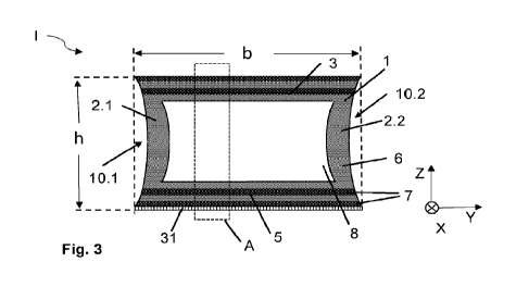
25 Figure 3 shows a cross-section through a possible spacer I according to
the
invention. Figure 5 shows the detail A from Figure 3 for a detailed view of
the
layer structure in the glazing interior wall 3 and the outer wall 5. The
spacer I
comprises a coextruded hollow profile 1 extending in the longitudinal
direction
(X) and having a first side wall 2.1, a second side wall 2.2, a glazing
interior
30 wall 3 and an outer wall 5 extending parallel thereto. The glazing
interior wall
3 connects the two side walls 2.1 and 2.2. The outer wall 5 is opposite the
glazing interior wall 3 and connects the two side walls 2.1 and 2.2. The first
CA 03204119 2023- 7- 4
side wall 2.1 and the second side wall 2.2 are curved in the direction of the
cavity 8 so that a first recess 10.1 for the primary sealant is provided
between
the first side wall 2.1 and the first pane, and a second recess 10.2 for the
primary sealant is provided between the second side wall 2.2 and the second
5 pane. The recesses provide the possibility of introducing more primary
sealant
than in the case of a completely planar side wall. This improves the stability
of
the seal along the side walls. In addition, the primary sealant is prevented
in
the event of strong solar radiation from flowing into the inner pane
interspace
and becoming visible there. The two side walls 2.1 and 2.2 are curved to the
10 same extent in the direction of the cavity 8 so that the recesses 10.1
and 10.2
are of the same size and the spacer has a symmetrical structure. The
symmetry in this case is in relation to the axis of symmetry S, as shown in
Figure 4.
15 The hollow profile 1 is a coextruded hollow profile which is coextruded
from a
polymeric base material 6 and a diffusion barrier material 7. The first side
wall
2.1 and the second side wall 2.2 consist of the base material 6. This is cost-
effective and, as a symmetrical structure, particularly stable. Two layers of
the
diffusion barrier material and two layers of the polymeric base material are
in
20 each case arranged alternately in the outer wall 5 and in the glazing
interior
wall 3. The layers of the diffusion barrier material in the outer wall 5 and
in the
glazing interior wall 3 extend over the entire width b of the hollow profile
and
thus ensure good sealing of the spacer. The individual layers of the materials
in the glazing interior wall 3 and the outer wall 5 are arranged continuously,
25 i.e., without interruption, in the longitudinal direction X and run
parallel to the
respective wall. The base material 6 used was, for example, polyamide 6.6,
and polyamide 6.6 with 25% by volume of sheet silicate was used as the
diffusion barrier material 7. A completely metal-free spacer is thus obtained.
This ensures particularly low heat conduction through the spacer. The inner
30 layer 6.2 of the outer wall and of the glazing interior wall 3 each
consist of
polymeric base material. The cavity 8 is thus completely delimited by the base
material 6, and diffusion-barrier material 7 is arranged on the side of the
hollow
21
CA 03204119 2023- 7- 4
profile I that faces the outer pane interspace. Since the outer layer 7.1
consists
of diffusion-barrier material 7, maximum protection against the penetration of
moisture and against gas loss from the inner pane interspace is ensured.
5 An adhesive layer 31 is arranged on the outer wall 5 on the side facing
the
external environment. The adhesive layer 31 is in contact with the secondary
sealant in the finished insulating glass unit. In the example, the adhesive
layer
31 is coextruded with the hollow profile 1 and consists substantially of PE
with
10% by weight of SiOx as the adhesion-promoting additive. The adhesive layer
10 31 has a better adhesion to the secondary sealant so that the long-term
stability of the edge composite is further improved thanks to the structure
according to the invention. The thickness of the adhesive layer 31 in the
example is approximately 100 pm.
15 The wall thickness d of the hollow profile is approximately 1 mm. The
wall
thickness is essentially the same everywhere. This improves the stability of
the
hollow profile and simplifies production. The hollow profile 1 has, for
example,
a height h of 6.5 mm and a width b of 12.5 mm. The width extends in the Y
direction from the first side wall 2.1 to the second side wall 2.2, measured
at
20 the widest point of the hollow profile along the glazing interior wall 3
or the
outer wall 5. The widths b at the heights of the glazing interior wall 3 and
of the
outer wall 5 are the same. The outer wall 5, the glazing interior wall 3 and
the
two side walls 2.1 and 2.2 enclose the cavity 8. The cavity 8 can receive a
desiccant 11. Perforations (not shown here), which produce a connection to
25 the inner pane interspace in the insulating glass unit, are formed in
the glazing
interior wall 3. The desiccant 11 can then absorb moisture from the inner pane
interspace 15 via the perforations in the glazing interior wall 3. No
additional
barrier film is arranged on the outer wall 5 since the layers of sheet
silicate
completely assume the barrier function. The layers of base material 6 each
30 have a thickness of 250 pm and the layers of diffusion-barrier material
7 each
have a thickness of approximately 250 pm.
22
CA 03204119 2023- 7- 4
Figure 4 shows a spacer which is basically constructed like the spacer shown
in Figure 3. In contrast to the spacer shown in Figure 3, all walls 3, 2.1,
2.2 and
of the hollow profile 1 in the example comprise two layers of diffusion
barrier
material 7 and two layers of base material 6. This structure with the same
5 number of layers in all walls can be coextruded particularly well. The
layers of
base material 6 and the layers of diffusion-barrier material 7 are arranged
continuously around the cavity 8 so that each layer extends from the outer
wall
5 across the first side wall 2.1 across the glazing interior wall 3 across the
second side wall 2.2 to the outer wall 5. This results in a nested onion-like
10 structure with alternating layers of the two materials. This has proven
to be
particularly stable and can be coextruded very well. The inner layer arranged
on the side facing the cavity consists in the example of the base material 6
so
that the outer layer consists of diffusion-barrier material 7. This offers
maximum protection against the penetration of moisture and against the loss
15 of gas. The layers of diffusion-barrier material 7 have a thickness of
200 pm
each and the layers of the polymeric base material have a thickness of 300
pm. An opaque decorative layer 9 in the form of a black PET film, which hides
the underlying hollow profile 1 from view, is glued to the side of the glazing
interior wall 3 that faces the glazing interior. This is particularly
advantageous
20 if the base material 6 in the example is a recycled polypropylene and
the
diffusion-barrier material 7 is an EVOH. The recycled polypropylene is then
effectively covered and a visually pleasing image is produced for the user of
the insulating glass unit. In order to improve the adhesion to the secondary
sealant, an adhesive layer 31 in the form of a silicon dioxide layer of
25 approximately 30 nm thickness is arranged on the outer wall 5 and is
applied
in the example by means of PYROSILO-V.
Figure 6 shows a cross-section of the edge region of an insulating glass unit
II
according to the invention with the spacer I shown in Figure 4. The first pane
30 13 is connected to the first side wall 2.1 of the spacer I by means of a
primary
sealant 17, and the second pane 14 is attached to the second side wall 2.2 by
means of the primary sealant 17. The primary sealant 17 is essentially a
23
CA 03204119 2023- 7- 4
crosslin king polyisobutylene. The inner pane interspace 15 is located between
the first pane 13 and the second pane 14 and is delimited by the glazing
interior
wall 3 of the spacer I according to the invention. The inner pane interspace
15
is air-filled or filled with an inert gas, such as argon. The cavity 8 is
filled with
5 a desiccant 11, for example a molecular sieve. The cavity 8 is connected
to the
inner pane interspace 15 via perforations 24 in the glazing interior wall 3.
Through the perforations 24 in the glazing interior wall 3, a gas exchange
takes
place between the cavity 8 and the inner pane interspace 15, wherein the
desiccant 11 absorbs the air moisture from the inner pane interspace 15. The
10 first pane 13 and the second pane 14 project beyond the side walls 2.1
and
2.2 so that an outer pane interspace 16 is produced, which is located between
the first pane 13 and the second pane 14 and is delimited by the outer wall 5
with the adhesive layer 31 of the spacer I. The edge of the first pane 13 and
the edge of the second pane 14 are arranged at the same height. The outer
15 pane interspace 16 is filled with a secondary sealant 18. The secondary
sealant 18 in the example is a polysulfide. Polysulfides absorb the forces
acting
on the edge composite particularly well and thus contribute to high stability
of
the insulating glass unit II. The adhesion of polysulfides to the adhesive
layer
of the spacer according to the invention is excellent. The first pane 13 and
the
20 second pane 14 consist of soda-lime glass of a thickness of 3 mm.
Fig. 7 shows the flow chart of a method according to the invention for
producing
an insulating glass unit II according to the invention. In a first step I, a
spacer I
according to the invention is provided. In a second step II, the spacer I is
joined
25 together to form a spacer frame. In a third step III, a first pane 13
and a second
pane 14 are provided. Alternatively, the third step III may also take place
before
the first step I. In a fourth step IV, the spacer I is fastened between the
first
pane 13 and the second pane 14 by means of a primary sealant 17. In a fifth
step V, the pane arrangement of the panes 13, 14 and the spacer I is
30 compressed in an insulation glass press. In a sixth step VI, the outer
pane
interspace 16 is at least partially filled with a secondary sealant 18.
24
CA 03204119 2023- 7- 4
List of reference signs
I Spacer
ll Insulating glass unit, insulating glazing
5 1 Hollow profile
2.1 First side wall
2.2 Second side wall
3 Glazing interior wall
Outer wall
10 5.1, 5.2 The portions of the outer wall that are closest to the side
walls
6 Base material, polymeric base material
6.1, 6.2 First and second layers of base material
7 Diffusion-barrier material
7.1, 7.2 First and second layers of diffusion-barrier
material
8 Cavity
9 Decorative layer
10 Recess, cutout
10.1, 10.2 First or second recess
11 Desiccant
20 13 First pane
14 Second pane
15 Inner pane interspace
16 Outer pane interspace
17 Primary sealant
25 18 Secondary sealant
24 Perforation in the glazing interior wall
31 Adhesive layer
X Longitudinal direction, extension direction of the
hollow profile
Y Transverse direction
30 Z Height direction
d Wall thickness
h Height of the base body
CA 03204119 2023- 7- 4
b Width of the base body
26
CA 03204119 2023- 7- 4