Note: Descriptions are shown in the official language in which they were submitted.
WO 2022/148852
PCT/EP2022/050295
1
Mitioatino vibrations in wind turbines
The present application claims the benefit of European patent application n
EP 21 382
003.8 filed on January 10th, 2021.
The present disclosure relates to wind turbine blades and methods for reducing
vibrations in wind turbines. More particularly, the present disclosure relates
to devices
for mitigating vortex induced vibrations and stall induces vibrations, and
methods for
reducing wind turbine vibrations when the wind turbine is parked, especially
during
wind turbine installation.
BACKGROUND
Modern wind turbines are commonly used to supply electricity into the
electrical grid.
Wind turbines of this kind generally comprise a tower and a rotor arranged on
the tower.
The rotor, which typically comprises a hub and a plurality of blades, is set
into rotation
under the influence of the wind on the blades. Said rotation generates a
torque that is
normally transmitted through a rotor shaft to a generator, either directly or
through the
use of a gearbox. This way, the generator produces electricity which can be
supplied
to the electrical grid.
The wind turbine hub may be rotatably coupled to a front of the nacelle. The
wind
turbine hub may be connected to a rotor shaft, and the rotor shaft may then be
rotatably
mounted in the nacelle using one or more rotor shaft bearings arranged in a
frame
inside the nacelle. The nacelle is a housing arranged on top of a wind turbine
tower
that may contain and protect the gearbox (if present) and the generator (if
not placed
outside the nacelle) and, depending on the wind turbine, further components
such as
a power converter, and auxiliary systems.
There is a trend to make wind turbine blades increasingly longer to capture
more wind
and convert the energy of the wind into electricity. That makes blades more
flexible
and more prone to vibrations of the blades. Wind turbine blades vibrating
excessively
may get damaged. Vibrations of the rotor blades may also result in the whole
wind
turbine structure oscillating e.g. fore-aft oscillations, or sideways
oscillations. Vibrations
in the wind turbine blade may also damage other components of the wind turbine
due
to excessive stress.
CA 03204130 2023- 7- 4
WO 2022/148852
PCT/EP2022/050295
2
When the wind turbine is in operation (i.e. producing energy), a wind turbine
controller
may operate auxiliary drive systems such as a pitch system or a yaw system to
reduce
or change loads on the blades. This way, vibrations of the blades may be
counteracted.
However, the problem of vibrations can be serious as well in circumstances
when the
wind turbine is parked.
When a wind turbine is parked, the wind may blow against the wind turbine from
unusual directions, i.e. different from normal operation. The airflow around
the wind
turbine may cause the wind turbine to vibrate. Vibrations may stress and even
damage
one or more wind turbine components, which may compromise the performance of
the
wind turbine, may increase the need of reparations and may reduce the lifespan
of the
wind turbine. As an orientation of a wind turbine blade may not be adapted to
the
direction of the incoming wind, e.g. through yawing and/or pitching as when
the wind
turbine is operating, the effects of vibrations may be greater or different
when the wind
turbine is parked than when the wind turbine is operating normally and
producing
energy.
In particular, this may apply when the wind turbine is being installed or
commissioned.
For example, it may happen that an incomplete rotor is installed (e.g. a rotor
having a
single blade or two blades out of the total of three blades). Only a few days
or a week
later, the remaining blades may be installed. In the meantime, the partially
installed (or
"incomplete") rotor may be in standstill. The rotor may or may not be locked,
and the
wind turbine can be exposed to varying wind conditions. This may likewise
apply if the
wind turbine is stopped during several hours, days or weeks, e.g. for
maintenance
reasons. A wind turbine blade may start to vibrate in any of these conditions
depending
particularly on the direction of the wind.
SUMMARY
In a first aspect of the present disclosure, a device for mitigating
vibrations of a blade
of a wind turbine during standstill is provided. The device comprises a
flexible base
having a first connection area and a second connection area, the first
connection area
being configured to be attached to the second connection area to form a
removable
attachment. The device further comprises one or more airflow modifying
elements
attached to the flexible base. The flexible base is configured to fit around a
portion of
CA 03204130 2023- 7- 4
WO 2022/148852
PCT/EP2022/050295
3
the rotor blade such that the removable attachment is positioned substantially
at a
leading edge of the blade.
In accordance with this aspect, a device is provided which can be fitted, e.g.
wrapped
around a portion of the wind turbine blade. The base is flexible so as to
conform to an
outer surface of the blade. The airflow modifying elements can affect the flow
around
the blades so as to reduce or avoid undesirable aerodynamic effects, and
particularly
aerodynamic effects causing vibrations of the blade. The attachment of
portions of the
flexible base is removable, and is located at or near a leading edge of the
blade.
Removal of the device from around the blade is thus facilitated, and problems
related
to serrated edges of the trailing edge of the blade may be avoided.
In a further aspect, the present disclosure provides a method for mitigating
vibrations
in a parked wind turbine blade comprising a leading edge, a trailing edge, a
tip and a
root. The method comprises providing a flexible base having a first connection
area
and a second connection area, wherein the first connection area is configured
to be
attached to the second connection area to form a removable attachment, and the
flexible base carries one or more airflow modifying elements. The method
comprises
wrapping the flexible base around a portion of the wind turbine blade and
attaching the
first connection area to the second connection area substantially along the
leading
edge of the wind turbine blade. The method then comprises installing the wind
turbine
blade.
In accordance with this aspect, a method for mitigating vibrations in a parked
wind
turbine blade, and particularly during installation, is provided. The flexible
base may be
temporarily wrapped around a wind turbine blade, and may be removed prior to
operation of the wind turbine. By placing the removable attachment near a
leading
edge, removal of the flexible base is facilitated by avoiding serrated edges
of the trailing
edge of the blade.
In yet a further aspect, a sleeve for wrapping around a portion of a wind
turbine blade
is provided. The sleeve comprises a first attachment portion, and a second
attachment
portion, wherein the first and second attachment portions are configured to
form a
removable connection. The sleeve further comprises one or more pockets with
filler
materials to form airflow modifying elements.
CA 03204130 2023- 7- 4
WO 2022/148852
PCT/EP2022/050295
4
In accordance with this aspect, a sleeve is provided which can help to avoid
vibrations
of blades. Pockets can be filled with filler material that provide a suitable
outer shape
of the sleeve. The pockets, when filled with filler material, can form an
airflow modifying
element to influence the flow around the blade and thereby avoid vibrations.
Throughout the present disclosure, the terms "standstill" and "parked" are
used
interchangeably, and may be understood as a situation in which the wind
turbine is not
producing electricity, and the rotor is substantially standing still. The
rotor may or may
not be locked in standstill. For instance, a wind turbine may be parked or in
standstill
during installation and/or commissioning. A wind turbine may also be parked
for e.g.
maintenance reasons after operating normally, i.e. producing energy.
BRIEF DESCRIPTION OF THE DRAWINGS
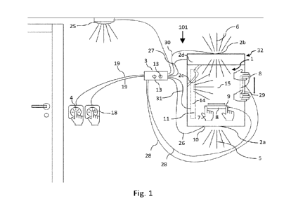
Figure 1 illustrates a perspective view of one example of a wind turbine;
Figure 2 illustrates a simplified, internal view of one example of the nacelle
of the wind
turbine of the figure 1;
Figure 3 schematically illustrates a wind turbine blade according to an
example;
Figures 4A ¨ 4C schematically illustrate different views of a device for
reducing
vibrations in a wind turbine blade;
Figure 4D schematically illustrates a cross-sectional view and a top view of a
sleeve
according to an example;
Figure 5 schematically illustrates a sleeve according to an example mounted to
a wind
turbine blade, e.g. to a tip region of a wind turbine blade;
Figures 6A and 6B show omegas and how omegas may be used to attach the sleeve
according to an example;
Figures 7 schematically illustrates a further example of a devices for
mitigating
CA 03204130 2023- 7- 4
WO 2022/148852
PCT/EP2022/050295
vibrations fitted around a wind turbine blade;
Figure 8 schematically illustrates a further example of a wind turbine blade
with two
devices fitted around portions of the blade; and
5
Figures 9A and 9B schematically represent examples of a method for mitigating
vibrations of a parked wind turbine by installing a sleeve around a portion of
the blade,
and a method for removing such a sleeve.
DETAILED DESCRIPTION OF EXAMPLES
Reference now will be made in detail to embodiments of the invention, one or
more
examples of which are illustrated in the drawings. Each example is provided by
way of
explanation of the invention, not as a limitation of the invention. In fact,
it will be
apparent to those skilled in the art that various modifications and variations
can be
made in the present invention without departing from the scope or spirit of
the invention.
For instance, features illustrated or described as part of one embodiment can
be used
with another embodiment to yield a still further embodiment. Thus, it is
intended that
the present invention covers such modifications and variations as come within
the
scope of the appended claims and their equivalents.
Figure 1 illustrates a perspective view of one example of a wind turbine 160.
As shown,
the wind turbine 160 includes a tower 170 extending from a support surface
150, a
nacelle 161 mounted on the tower 170, and a rotor 115 coupled to the nacelle
161.
The rotor 115 includes a rotatable hub 110 and at least one rotor blade 120
coupled to
and extending outwardly from the hub 110. For example, in the illustrated
embodiment,
the rotor 115 includes three rotor blades 120. However, in an alternative
embodiment,
the rotor 115 may include more or less than three rotor blades 120. Each rotor
blade
120 may be spaced about the hub 110 to facilitate rotating the rotor 115 to
enable
kinetic energy to be transferred from the wind into usable mechanical energy,
and
subsequently, electrical energy. For instance, the hub 110 may be rotatably
coupled to
an electric generator 162 (figure 2) positioned within the nacelle 161 to
permit electrical
energy to be produced.
Figure 2 illustrates a simplified, internal view of one example of the nacelle
161 of the
CA 03204130 2023- 7- 4
WO 2022/148852
PCT/EP2022/050295
6
wind turbine 160 of figure 1. As shown, the generator 162 may be disposed
within the
nacelle 161. In general, the generator 162 may be coupled to the rotor 115 of
the wind
turbine 160 for generating electrical power from the rotational energy
generated by the
rotor 115. For example, the rotor 115 may include a main rotor shaft 163
coupled to
the hub 110 for rotation therewith. The generator 162 may then be coupled to
the rotor
shaft 163 such that rotation of the rotor shaft 163 drives the generator 162.
For
instance, in the illustrated embodiment, the generator 162 includes a
generator shaft
166 rotatably coupled to the rotor shaft 163 through a gearbox 164.
It should be appreciated that the rotor shaft 163, gearbox 164, and generator
162 may
generally be supported within the nacelle 161 by a support frame or bedplate
165
positioned atop the wind turbine tower 170.
The nacelle 161 is rotatably coupled to the tower 170 through the yaw system
20 in
such a way that the nacelle 161 is able to rotate about a yaw axis YA. The yaw
system
comprises a yaw bearing having two bearing components configured to rotate
with
respect to the other. The tower 170 is coupled to one of the bearing
components and
the bedplate or support frame 165 of the nacelle 161 is coupled to the other
bearing
component. The yaw system 20 comprises an annular gear 21 and a plurality of
yaw
20 drives 22 with a motor 23, a gearbox 24 and a pinion 25 for meshing with
the annular
gear 21 for rotating one of the bearing components with respect to the other.
Blades 120 are coupled to the hub 110 with a pitch bearing 100 in between the
blade
120 and the hub 110. The pitch bearing 100 comprises an inner ring and an
outer ring.
A wind turbine blade may be attached either at the inner bearing ring or at
the outer
bearing ring, whereas the hub is connected at the other. A blade 120 may
perform a
relative rotational movement with respect to the hub 110 when a pitch system
107 is
actuated. The inner bearing ring may therefore perform a rotational movement
with
respect to the outer bearing ring. The pitch system 107 of Figure 2 may
comprise a
pinion 108 that meshes with an annular gear 109 provided on the inner bearing
ring to
set the wind turbine blade into rotation around a pitch axis PA.
A schematic perspective view of a wind turbine blade 120, e.g. one of the
rotor blades
120 shown in figure 1, is illustrated as an example in figure 3. The rotor
blade 120
includes a blade root 210, a blade tip 220, a leading edge 260 and a trailing
edge 270.
CA 03204130 2023- 7- 4
WO 2022/148852
PCT/EP2022/050295
7
The blade root 210 is configured for mounting the rotor blade 120 to the hub
110 of a
wind turbine 160. The wind turbine blade 120 extends lengthwise between the
blade
root 210 and the blade tip 220. A span 230 defines a length of the rotor blade
120
between said blade root 210 and blade tip 220. A chord 280 at a given position
of the
blade is an imaginary straight line joining the leading edge 260 and the
trailing edge
270, the cross-section generally having airfoil shaped cross-section. As is
generally
understood, a chordwise direction is substantially perpendicular to a spanwise
direction. Also, the chord 280 may vary in length 285 as the rotor blade 120
extends
from the blade root 210 to the blade tip 220. The wind turbine blade 120 also
includes
a pressure side 240 and a suction side 250 extending between the leading edge
260
and the trailing edge 270. A tip region 225 may be understood as a portion of
a wind
turbine blade 120 that may be close to the tip 220. The rotor blade 120, at
different
spanwise positions, has different aerodynamic profiles and thus can have
airfoil shaped
cross-sections 290, such as a symmetrical or cambered airfoil-shaped cross-
section.
Close to a root of the blade, the cross-section of the blade may be rounded,
even
circular or almost circular. Closer to a tip of the blade, the cross-section
of the blade
may have an airfoil shape.
When a wind turbine is parked or stopped, vibrations caused by the air flowing
around
the wind turbine, in particular around the wind turbine blades, may stress and
damage
the wind blades and the wind turbine. The wind turbine rotor may or may not be
locked
in these situations.
At least two oscillations or vibrations may happen particularly when the
turbine is
parked. The first ones are so-called vortex induced vibrations (VIVs), and may
arise
when an angle of attack for a blade or airfoil portion is around 90 degrees.
Vortex
shedding may contribute to enhance the wind turbine blade oscillation. The
second
ones are stall induced vibrations (SIVs), and may arise when the angle of
attack is
close to stall angles (e.g. 15 degrees - 20 degrees). The angle of attack may
be
understood as a geometrical angle between a flow direction of the wind and the
chord
of a rotor blade.
Devices or sleeves 300 as described herein may reduce vibrations when the wind
turbine is parked and the performance of the wind turbine may not be
negatively
affected as the sleeve may be removed before the wind turbine starts normal
operation.
CA 03204130 2023- 7- 4
WO 2022/148852
PCT/EP2022/050295
8
Such a sleeve 300 may be particularly useful during installation and/or
commissioning
of a wind turbine. It may be also useful if the wind turbine is stopped, e.g.
for
maintenance.
Figures 4A ¨ 40 schematically illustrate different views of a device for
reducing
vibrations in a wind turbine blade;
Figure 4A schematically illustrates a device for mitigating vibrations of a
blade 120 of
a wind turbine during standstill. The device comprises a flexible base 300
having a first
connection area and a second connection area, the first connection area being
configured to be attached to the second connection area to form a removable
attachment. The device may include one or more airflow modifying elements 360
attached to the flexible base, and the flexible base 300 is configured to fit
around a
portion of the rotor blade such that the removable attachment is positioned
substantially
at a leading edge 260 of the blade.
The flexible base is flexible enough to conform at least partially to an outer
surface of
the blade i.e. it is not necessary that the flexible base follows the outer
contour of the
blade very strictly.
The device may be formed as a sleeve, or may be formed into a sleeve e.g. by
folding
upon itself. A sleeve may herein be regarded as a cover that can be wrapped
around
a portion of the blade to cover the portion, and thereby assumes a somewhat
cylindrical
shape. The sleeve does not need to be continuous around 360 and may comprise
a
plurality of openings or transparent or translucent portions for allowing
viewing of the
blade, and may in some examples with openings or cut-outs include strips 390
of
material to complete the 360 around the portion of the blade.
The removable attachment may be configured to be opened remotely. Thus, when
the
blade is mounted to the hub, the attachment may be removed by an operator(s).
The
operator(s) may in different examples be in the hub, in a crane, or on the
ground for
removing the attachment.
In some examples, the removable attachment may comprise a removable locking
element 590. The removable locking element may be a pin or cable that
maintains
CA 03204130 2023- 7- 4
WO 2022/148852
PCT/EP2022/050295
9
fasteners in place. In a specific example, the locking element may be a steel
cable with
a plastic cover.
In some examples, the device may comprise a line 580 attached to the removable
locking element, see e.g. figure 4C. A line may herein be regarded as any kind
of cable,
cord, or rope. The line may be held by an operator or device positioned in the
hub to
pull the locking element 590.
In some examples, the first connection area of the device may include a first
series of
fasteners 584, and the second connection area includes a second series of
fasteners
582, wherein the first series of fasteners is configured to mate with, engage
with or fit
in the second series of fasteners 582, and wherein the first fasteners 584 are
secured
to the second fasteners 582 with the removable locking element 590. In the
example
of figure 4C, the fasteners may interleave, i.e. the first series of fasteners
is positioned
in between the second series of fasteners. In other examples, the first series
of
fasteners may be male fasteners, and the second series of fasteners may be
female
fasteners. The removable locking element may keep the male fasteners
positioned
within the female (receiving) fasteners.
In yet further examples, the removable attachment may include magnets, a
zipper or
hook-and-loop fasteners, e.g. VelcroTM.
In some examples, the flexible base may be textile based, e.g. PVC fabrics
such as
used in tarps may be used. The fabric may be coated for improved weather
resistance.
A textile based flexible base may be easily fitted around a portion of a wind
turbine
blade. When fitted around the portion of the blade, a cover or sleeve may be
formed.
Optionally, the flexible base may comprise one or more tighteners for
tightening the
flexible base around the portion of the rotor blade. A tightener 390 may
include a first
attachment point (which may be sewn or otherwise attached to the flexible
base), a
second attachment point, and a strip of material extending between the two
attachment
points. By pulling on the strip, the attachment points may be brought closer
to each
other, and the flexible base may thus be pulled tighter. The tightener may
include a
ratchet strap.
Textile based flexible bases with tighteners can be used on different blades,
and may
CA 03204130 2023- 7- 4
WO 2022/148852
PCT/EP2022/050295
be used on different portions of blades. In such examples, there is no need to
make
blade-specific devices and instead the same device can be used on blades with
different dimensions.
5 With reference again to figure 4, one or more of the airflow modifying
elements 360
may be incorporated in the flexible base. Being incorporated in the flexible
base may
herein be understood as being included on an inside of the flexible base. I.e.
an outer
surface of the airflow modifying element is formed by the flexible base. In
other
examples, the airflow modifying elements may be mounted on an outer surface of
the
10 flexible base.
Airflow modifying elements or "deflectors" may have any suitable shape to
significantly
disturb the flow around a wind turbine blade. In particular, the airflow
modifying
elements may be chosen such that a spanwise component of an airflow is made
more
turbulent, or to make vortex sheddings uncoherent along the blade span. These
two
effects particularly may affect the occurrence of vortex induced and stall
induced
vibrations.
As shown in figure 4, and will be further explained herein, the flexible base
may
comprise one or more pockets holding a filler material to form one or more of
the airflow
modifying elements. A filler material may be e.g. a foam, or bulk material. By
filling the
pockets, the filler material gives some structural strength and stiffness to
the otherwise
loose and flexible pockets. The pockets may thus assume a suitable outer shape
to
disturb or affect the flow around the blade.
In examples, one or more of the airflow modifying elements may (also) be
mounted at
an outer surface of the flexible base. Any suitable airflow modifying element
including
e.g. a net, blocks, a straight or curved plate or fence may be used.
In some examples, one or more protectors 593 may be provided at an inside
surface
of the flexible base configured to be placed at a or near a trailing edge of
the portion of
the blade. Such protectors, shown e.g. in figure 4B may separate serrated
edges of
the blade from the sleeve, in order to protect tearing of the device or sleeve
by serrated
edges, and/or in order to avoid damages to serrated edges.
CA 03204130 2023- 7- 4
WO 2022/148852
PCT/EP2022/050295
11
In accordance with a further aspect, a sleeve 300 may be provided for wrapping
around
a portion of a wind turbine blade 120. The sleeve may comprise a first
attachment
portion, and a second attachment portion, wherein the first and second
attachment
portions are configured to form a removable connection, and the sleeve further
comprising one or more pockets 325 with filler materials to form airflow
modifying
elements.
In some examples, as will be illustrated herein, one or more of the airflow
modifying
elements 330 may be configured to extend along a local chord direction (see
e.g. figure
4D).
In some examples, one or more of the airflow modifying elements 360 are
configured
to extend along a spanwise direction, see e.g. figure 4A.
In some examples, the sleeve may comprise a plurality of airflow modifying
elements
extending along a spanwise direction near a leading edge (see e.g. figure 5)
and a
plurality of airflow modifying elements extending along a spanwise direction
near a
trailing edge (see e.g. figure 8).
In some examples, the sleeve may comprise airflow modifying elements both at a
suction surface and at a pressure surface of the wind turbine blade (see e.g.
figure 8).
Figure 4D schematically illustrates a top view of an example of a sleeve 300
and a side
view (cross section along lines A-A') for wrapping a wind turbine blade 120,
e.g. the
wind turbine blade of figure 2 or a wind turbine blade 120 of the wind turbine
160 of
figure 1.
In figure 4D, the sleeve 300 is unfolded. The sleeve 300 comprises a flexible
base 301,
the base 301 including an inner surface 305 configured to be placed facing the
wind
turbine blade 120, e.g. a suction side 250 and a pressure side 240, and an
outer
surface 310 configured to be placed facing away from the wind turbine blade
120. The
flexible base in this example when unfolded has a substantially trapezoid
shape. In
other examples, the flexible base when unfolded may e.g. be substantially
rectangular.
The base 301 in this example further comprises a first connection area (in
this example,
CA 03204130 2023- 7- 4
WO 2022/148852
PCT/EP2022/050295
12
a first attachment edge) 315 and a second connection area (in this example, a
second
attachment edge) 320, the first 315 and second 320 attachment edges being
configured to be placed along a leading edge 260. A sleeve 300 attached to a a
portion
of a blade may be seen in figure 5.
The sleeve 300 in this example further comprises a first pocket 325 configured
to hold
filler material 410 inside the first pocket 325. The first pocket 325 is
configured to
protrude outwards from the outer surface 310 when filled with a filler
material 410.
Accordingly, the first pocket 325 and the filler 410 may form an airflow
modifying
element 412. The airflow modifying element 412 may thus act as a vibration
reducing
element 412: by suitably modifying airflow around the blade, ViV and SiV may
be
avoided e.g. by causing an airflow to separate from the blade surface, by
making the
flow more turbulent, or diverting the flow in a certain direction.
An airfoil modifying element may be formed in this example as a pocket filled
with a
filler material conferring structural rigidity to the pocket. The filler
material 410 may
completely fill an inside of the pocket for increased stiffness.
In some examples, a filler material 410 may be a block of foam rubber of
substantially
the same size of the first pocket 325. In some other examples, a filler
material 410 may
be a plurality of blocks of foam rubber which may fill an inside of the first
pocket 325
entirely.
When wrapped and releasably attached to a wind turbine blade 120, in
particular to a
tip region 225 of the wind turbine blade 120, the sleeve 300, and in
particular the first
vibration reducing element 412 may mitigate blade 120 vibrations when a wind
turbine
160 is parked.
For instance, such a sleeve 300 and the first vibration reducing element 412
may
mitigate wind turbine blade 120 vibrations when a wind turbine 160 is being
installed
and/or during commissioning of the wind turbine 160. Advantageously, the
sleeve 300
may be removed from around the wind turbine blade 120 before the wind turbine
160
starts normal operation, i.e. to produce energy. Accordingly, wind turbine
blade 120
vibrations may be mitigated when the wind turbine blade 160 is parked without
negatively affecting the performance of the wind turbine 160 during subsequent
normal
CA 03204130 2023- 7- 4
WO 2022/148852
PCT/EP2022/050295
13
operation.
As illustrated in the example of figure 5, the first pocket 325 (and in
general any pocket
that the sleeve may include) has a height 415, a width 420 and a length 425.
In some
examples, the first pocket 325 may be located in the sleeve 300, i.e. oriented
with
respect to the sleeve base 301, such that a direction substantially parallel
to a length
425 of the first pocket 325 (when filled with filler material as in figure 5)
lies substantially
parallel to a leading edge 260 when the sleeve 300 is wrapped around and
attached to
a wind turbine blade 120. The airflow modifying element or deflector in this
case
extends substantially along a spanwise direction, and particularly near a
leading edge
of the blade.
In some other examples, the first pocket 325 may be arranged with the sleeve
300
such that a direction substantially parallel to a length 425 of the first
pocket 425 (when
acting as a vibration reducing element 412) lies substantially parallel to a
trailing edge
270 when the sleeve 300 is wrapped around and attached to a wind turbine blade
120.
If the leading edge 260 and the trailing edge 270 were substantially parallel
to one
another, a length 425 of the first pocket 325 may be substantially parallel to
both the
leading edge 260 and the trailing edge 270.
Aligning a length 425 of the first pocket 325 with a leading 260 and/or a
trailing 270
edge may be particularly effective for reducing stall-induced vibrations.
In some examples, the first pocket 325 may include opening and closing
fasteners 430,
e.g. a zipper, which allow the pockets to be opened and closed and thus enable
placing
filler material 410 inside the first pocket 325. In some examples, pockets
(with or
without filler material) may be removably attached to the sleeve using e.g.
zippers.
Pockets with filler materials may thus be attached in a suitable configuration
as needed.
In some examples, the pockets may be attached e.g. sewn to an outside of the
sleeve.
In some examples, the first pocket 325, and therefore the first airflow
modifying element
412, may have a height 415 between 10 and 100 cm, more particularly between 20
and 40 cm.
In some examples, a width 420 of the first pocket 325, and therefore a width
of the first
CA 03204130 2023- 7- 4
WO 2022/148852
PCT/EP2022/050295
14
airflow modifying element 412, may be substantially be the same as the height
415 of
the first pocket 325. In some other examples, the width 420 of the first
pocket 325 may
be larger or smaller than the height 415 of the first pocket 325.
In some examples, a length 425 of the first block 325 (i.e. a spanwise
extending block)
may be between 0.5 and 3 m, more in particular between 1 and 2 m. I.e. its
spanwise
extension be between 50 cm and 3 meters, and particularly between 1 and 2
meters.
In some examples, the sleeve 300 may further comprise an add-on "deflector"
330
attached to the outer surface 310 of the base 301 of the sleeve 300. An add-on
deflector 330 may perturbate or disturb air flowing around the wind turbine
blade 120
when the wind turbine blade 120 is mounted to a wind turbine 160 and the wind
turbine
160 is parked or stopped.
In some examples, a deflector 330 may be a substantially flat elongated plate.
In some examples, a deflector 330 may be glued, sewn or bolted to the outer
surface
310 of the base 301 of the sleeve 300.
In some examples, a deflector 330 may be made from light metals or composite
materials such as fiber-reinforced polymers. In some examples, a deflector 330
may
be made of carbon fiber or glass fiber. A deflector 330 may thus be strong and
lightweight.
In some examples, a deflector 330 may be made of porous materials. In some
examples, a deflector 330 may include holes, e.g. holes crossing a width 435
of the
deflector 330. In examples, the deflector 330 may be or comprise a net.
In some other examples, the sleeve 300 may comprise a second pocket 330'
instead
of the add-on deflector 330 attached to an outside of the sleeve. The second
pocket
330' is configured to hold filler material 410 inside the second pocket 330'.
Like the first
pocket 325, the second pocket 330' is configured to protrude outwards when
filled with
a filler material 410. Accordingly, the second pocket 330' and the filler 410
may act as
a second vibration reducing element or "airflow modifying element".
CA 03204130 2023- 7- 4
WO 2022/148852
PCT/EP2022/050295
In some examples, a direction substantially parallel to a length 440 of the
deflector 330
or of the second pocket 330' may be configured to lie substantially
perpendicular to a
leading edge 260 when the sleeve 300 is wrapped around and attached to a wind
turbine blade 120.
5
As doing so may particularly perturbate or disturb air flowing in a spanwise
direction,
this may help to decrease vortex induced vibrations.
In some examples, a top 331 of the deflector 330 may comprise irregularities,
e.g.
10 protrusions, or recesses/notches. I.e., the deflector 330 may
have a non-constant
height 445 along its length 440. A top 331 may be understood as a side of the
deflector
330 opposed to the side of the deflector 330 which is attached to the outer
surface 310
of the base 301 of the sleeve 300. Irregularities may include protrusions
and/or
recesses. The irregularities may extend over the entire top 331 of the
deflector 300 or
15 may extend over a portion of it.
In some examples, the add-on deflector 330 or the second pocket 330' may have
a
substantially same height 445 as the first pocket 325. In some other examples,
the
deflector 330 or the second pocket 330' may be taller than the first pocket
325. I.e., a
height 445 of the deflector 330 may be larger than a height 415 of the first
pocket 325.
In some examples, a height 445 of the chordwise extending deflector 330 or the
second
pocket 330' may be between 1.2 and 3 times bigger than a height 415 of the
spanwise
extending first pocket 325.
The higher the deflector 330 or the second pocket 330', the greater the
airflow
deflection and the vibration reduction may be.
In some examples, a length 440 of the deflector 330 or the second pocket 330'
(i.e. an
airflow modifying element extending predominantly in a chordwise direction)
may be
between 50 cm and 3m.
In some examples, a length 335 of a sleeve base 301 may be between 2 and 6 m,
and
more in particular between 4 and 5 m. In some examples, a width 340, 340' of a
sleeve
base 301 may be between 2 and 6 m.
CA 03204130 2023- 7- 4
WO 2022/148852
PCT/EP2022/050295
16
In some examples, the base 301 and pockets (e.g. the first 325 and second 330'
pockets) may be integrally formed. In some examples, the base 301 and the
pockets
301 may be made of plastic material. In an example, polyvinyl chloride (PVC)
may be
used.
As also illustrated in figures 4D and 5, additional pockets, e.g. a third
pocket 360, may
be provided in the sleeve 300. The number of pockets (and deflectors) as well
as their
location on the sleeve outer surface 310 may be chosen according to a desired
level
of vibration attenuation. Computer simulations, including e.g. computational
fluid
dynamics and finite element analysis may be used to select the number and
position
of the pockets and deflectors.
The sleeve 300 may have a first portion 365 configured to be placed on the
suction
side 250 and a second portion 370 configured to be placed on the pressure side
240.
Thus, pocket(s) and deflector(s) may be placed in at least one of the suction
side 250
and the pressure side 240. The examples of figure 4D shows that the sleeve 300
includes pockets and deflectors in both the first portion 365 and the second
portion
370. This may enhance vibration reduction with respect to examples where
vibration
reducing elements are placed only in one of the first or the second sleeve
portions.
In some examples, the sleeve 300 may include one or more tighteners 390, e.g.
ratchet
straps. The tighteners may help to adjust the sleeve 300 around the wind
turbine blade
120. The tighteners 390 may be sewn to the base 301 of the sleeve in some
examples.
In some examples, the sleeve 300 may further comprise a protection element
355,
attached to the inner surface 305 of the sleeve base 301 configured to be
placed along
a trailing edge 270. The protection element 355 may extend along an entire
length 335
of the sleeve 300. In some examples, the protection element 355 may be made of
foam. In some examples, the protection element 355 may be placed between the
first
portion 365 of the sleeve 300 and the second portion 370 of the sleeve 300,
e.g. as
illustrated in figure 4D.
The protection element 355 may prevent the serrations of a wind turbine blade
120 to
engage with the sleeve base 301. This may avoid the sleeve 300 getting stuck
on the
serrations when separating and descending the sleeve 300 from the wind turbine
blade
CA 03204130 2023- 7- 4
WO 2022/148852
PCT/EP2022/050295
17
120. The life service of the sleeve 300 may be extended and the lowering of
the sleeve
300 may be easier and faster than without the presence of the protection
element 355.
In some examples, the first connection area or attachment edge 315 may
comprise
holes or rings 375 as illustrated in figure 40. In some of these examples, the
second
connection area or attachment edge 320 may comprise brackets, e.g. omega
shaped
brackets 380 which may attached to the base 301, such that the rings may be
placed
over the corresponding omegas for closing the sleeve 300. A locking element or
pin
590 may be passed through the brackets 380, i.e. through holes 395 (see figure
6A),
in order to attach the first 315 and second 320 attachment edges to one
another and
retain them in that position.
In some other examples, the second attachment edge 320 may include the rings
375
and the first attachment edge 315 may include the brackets 380. Still in some
other
examples, the attachment edges 315, 320 may not have holes and attached
brackets,
but the holes may be made on site and the omegas 380 and bracket pins or bolts
385
for attaching the brackets 380 to e.g. the first attachment edge 315 used once
a wind
turbine blade 120 has been covered by the sleeve 300. It should also be clear
that the
omega shape of the brackets is merely one option, and that other rounded or
straight
shapes of brackets are possible as well.
Also, as noted before having the connection areas for forming a removable
attachment
at the edges of the flexible base is merely one example. In other examples,
the
connection areas are not necessarily located along opposite edges of a
flexible base.
When such a flexible base is formed into a sleeve an excess portion of
flexible base
may extends beyond the leading edge. Depending on the implementation,
fittings, or
mountings for handling may be included in such an excess portion.
In some examples, the omega shaped brackets 380 may include holes 395 (e.g.
through which a rope or cable (or other locking element) 590 may be passed.
Pulling
the locking element 590, e.g. by an operator, may cause the separation of the
first 315
and second 320 attachment edges. The locking element may have a feature to
ensure
that it does not move or falls out during installation and handling of the
blade. For
example, the locking element may have a tearable, or removable connection to
the
sleeve with e.g. adhesive tape. In other examples, the locking element 590 may
have
CA 03204130 2023- 7- 4
WO 2022/148852
PCT/EP2022/050295
18
a local widening or increased dimension that gives sufficient friction with
the (omega-
shaped) brackets 380 for maintaining the locking element in place during
handling, but
the friction can be overcome by an operator pulling.
As the locking element 590 may be operated from a distance from the sleeve 300
and
the blade 120, e.g. via a line 580 and from the hub, the sleeve 300 may be
easily and
rapidly lowered.
The locking element 590 may be attached, e.g. tied, to an end 505 of the first
315 or
second 320 attachment edges, as illustrated in figure 4D. Thus, if the rope
500 has
been passed through the holes 395 of the omegas 380 and tied to an end 505,
when
pulling the rope 590, the first 315 and second 320 attachment ends may start
to
separate at the opposite end (end 510) and continue separating towards where
the
rope 590 has been attached to 505.
Similarly, in figures 4A-40, the locking element 590 may be directly or
indirectly (e.g.
through an additional rope) attached to an end of a first or second connection
areas.
In these figures the locking element 590 may also have a diameter, in some
examples
a local diameter, which may provide sufficient friction with fasteners 582,
584 to keep
the connection areas attached.
In some examples, as illustrated in figure 6B, the brackets 380 may be
attached to a
first connection area, and to a second connection area. By removing a locking
element
590 the connection areas may be separated from each other.
In some examples, magnetic fasteners may be used to attach a first connection
area
to a second connection area. In further examples, frangible fasteners may be
used.
E.g. by pulling, the fasteners are broken.
Figure 7 schematically illustrates a further example of a device 300 for
mitigating
vibrations fitted around a wind turbine blade. The wind turbine blade of this
example
again includes a serrated trailing edge 270. The device 300 may again be
formed as a
flexible sleeve adapted to conform to an outer surface of the blade. As has
already
been illustrated in other examples, a removable attachment may be formed at or
near
a leading edge of the blade. A locking element 590 may be attached to a rope
580
CA 03204130 2023- 7- 4
WO 2022/148852
PCT/EP2022/050295
19
which may be pulled e.g. by an operator in the hub or nacelle. Removing the
locking
element can separate a first connection area configured to be attached to the
second
connection area from each other.
In the example of figure 7, the device 300 comprises a plurality of elongated
airflow
modifying elements 575. Pairs of the airflow modifying elements form a V-
shape. The
airflow modifying elements 575 may thus act as vortex generators. The airflow
modifying elements 575 may be formed as pockets filled with a suitable filler
material,
and/or may be elements or add-ons deflectors attached to an outside of the
device.
Figure 8 schematically illustrates a further example of a wind turbine blade
with two
devices fitted around portions of the blade. In this example, a pressure
surface 540 of
a blade 500 is shown. The blade 500 has a leading edge 560, and a trailing
edge 570.
Two devices or "sleeves" have been fitted at different spanwise positions
around
different portions of the blade. A first sleeve 513 may be closer to a root of
the blade,
e.g. at a spanwise position of between 30 and 70% of the span of the blade.
The sleeve
513 includes a plurality of (predominantly) spanwise extending airflow
modifying
elements 514, both near the leading edge and near the trailing edge of the
portion of
the blade. Sleeve 513 in this example also includes a plurality of
(predominantly)
chordwise extending airflow modifying elements 512. In this example, two of
the airflow
modifying elements 512 are arranged behind one another along a local chord of
the
blade. The chordwise extending airflow modifying elements may be higher than
the
other airflow modifying elements.
A second sleeve 530 may be fitted closer to a tip of the blade, e.g. at a
spanwise
position between 70 and 100% of the span of the blade, and in this example,
between
80 and 95% of the span of the blade. The sleeve 530 may have a similar
configuration
as sleeve 513. The sleeve 530 includes a plurality of (predominantly) spanwise
extending airflow modifying elements 532, both near the leading edge and near
the
trailing edge of the portion of the blade. Sleeve 530 in this example also
includes a
plurality of (predominantly) chordwise extending airflow modifying elements
534. In this
example, two of the airflow modifying elements 512 are arranged behind one
another
along a local chord of the blade.
The dimensions of the airflow modifying elements may be different in both
sleeves and
CA 03204130 2023- 7- 4
WO 2022/148852
PCT/EP2022/050295
tailored to local needs. In further examples, multiple sleeves may be attached
to the
same blade, and the airflow modifying elements in each of the sleeves may be
very
different.
5 Although not shown in all detail, it should be clear that sleeves 513 and
530 also
incorporate or carry airflow modifying elements at a suction surface of the
blade.
The airflow modifying elements of these examples may once again be formed as
pockets incorporated in the sleeve and filled with filler material, or may be
add-ons as
10 has been illustrated with reference to other examples.
In yet further examples, three or more sleeves may be fitted around different
portions
of a blade.
15 In another aspect, a method for mitigating vibrations for a parked wind
turbine blade
comprising a leading edge 260, a trailing edge 270, a tip 220 and a root 210
is provided.
The method may be used particularly during installation and/or during
commissioning
of the wind turbine. The method may potentially also be used when the wind
turbine
may be stopped after it has been operating (i.e. producing energy), e.g.
during
20 maintenance or repair.
The method of figure 9A comprises providing, at block 610, a wind turbine
blade. The
wind turbine blade may be a "standard" blade, i.e. it does not need to be
adapted in
any way to be suitable for the methods and devices provided herein.
At block 620, a sleeve is provided. The sleeve may comprise a flexible base
having a
first connection area and a second connection area, wherein the first
connection area
is configured to be attached to the second connection area to form a removable
attachment, and the flexible base carries one or more airflow modifying
elements. Any
of the herein disclosed examples of figures 4 ¨8 may be used.
At block 630, the flexible base may be wrapped around a portion of the wind
turbine
blade and the first connection area may be attached to the second connection
area
substantially along the leading edge of the wind turbine blade. The sleeve may
thus be
wrapped around a portion of the blade. In some examples, multiple sleeves may
be
CA 03204130 2023- 7- 4
WO 2022/148852
PCT/EP2022/050295
21
wrapped around the same blade. One sleeve may be closer to a tip of a blade,
e.g. at
a position between 70 and 100% of a span of the blade, and specifically
between 70
and 90% of a span. Another sleeve may be closer to a root of the blade, e.g.
at a
position between 30 and 70% of a span of the blade.
In some examples, wrapping may take place on the ground, and particularly
after a
blade has arrived at a wind turbine site. One or more operators may take the
sleeve
and place the inner surface of the sleeve base facing the wind turbine blade,
i.e. the
pressure side and the suction side of the blade.
For attaching the areas of the flexible base, brackets 380 and corresponding
bracket
pins 385 may be used in some examples, as explained with respect to figures
4D, 6A
and 6B. As also commented before, other fasteners may be used. For example,
the
two attachment edges 315, 320 may be put together by zipping a zipper. In
further
examples, the attachment edges may be connected to each other using Velcro or
similar.
In some examples, the pockets may be filled and/or the deflectors may be
attached to
the sleeve before wrapping the sleeve 300 around the blade 120. In some other
examples, this may be done before the wrapping. Still in some other examples,
this
may be done after the wrapping.
At block 640, the blade may then be installed. The sleeve may stay wrapped
around
the blade until operation is started. In examples, the method may further
comprise
removing the flexible base from the wind turbine blade prior to starting
operation.
In some examples, the sleeve may include some form of tightening mechanism
390.
Tightening one or more tighteners may be sufficient to adjust the sleeve 300
to the
blade 120 and attaching a rope to secure the sleeve 300 to the blade 120 when
lifting
the blade 120 may not be necessary.
When the sleeve 300 is wrapped and attached on the ground, the method may
further
comprise lifting the blade 120 and mounting it to the wind turbine. The blade
120 may
be first attached to the hub 110 and the hub 110 and the blade 120 may be
lifted
together, or the hub 100 may be mounted first and then the blade 120 with the
sleeve
CA 03204130 2023- 7- 4
WO 2022/148852
PCT/EP2022/050295
22
300 may be lifted and connected to the hub 110.
Once the blade 120 with the sleeve 300 is mounted to the wind turbine 160, the
vibration reducing elements, namely one or more filled pockets, and optionally
one or
more deflectors, may reduce wind turbine blade 120 vibrations, e.g. vortex
induced
vibrations and/or stall induced vibrations.
In some examples, the flexible base may be removed by positioning the rotor
blade in
a substantially horizontal position with the trailing edge pointing downwards;
and
detaching the first connection area from the second connection area.
In examples, a method according to figure 9B may be used for removing a sleeve
from
around the blade. At block 650, a wind turbine blade may be positioned in a
substantially horizontal position, i.e. close to a three o'clock position or
close to a nine
o'clock position. This may involve rotating the hub with blades to a suitable
position,
which may be done under the action of the wind, or may involve a specific tool
which
may act on a part of the geartrain to rotate the rotor.
When the wind turbine blade is in a substantially horizontal position, the
blade may be
pitched at block 660, if the trailing edge of the blade is not pointing
downwards yet.
This may involve pitching the blades e.g. over an angle of 90 .
When the trailing edge of the wind turbine blade is pointing downwards, the
removable
attachment at the leading edge is at an upper side of the blade. If the
attachment is
then removed, i.e. the sleeve is opened by separating the first and second
connection
areas or separating the first 315 and second 320 attachment edges, the sleeve
can fall
of the blade. In this manner, the sleeve may be removed from the blade, at
block 670,
and the serrated edges may not interfere, i.e. parts of the sleeve may not get
stuck on
the serrated edges. In particular, a protection element 355 may avoid the
sleeve getting
stuck with the wind turbine blade serrations.
In order to remove the sleeve, a locking element 590 as illustrated in other
examples
may be removed. The locking element 590 may be pulled e.g. from a hub of the
wind
turbine. The locking element 590 may be attached to a rope 580 from which an
operator
may pull the locking element 590. The rope 580 or locking element 590 may be
CA 03204130 2023- 7- 4
WO 2022/148852
PCT/EP2022/050295
23
attached to another point of the sleeve using e.g. a further rope or cable
with some
slack. In this manner, the sleeve may still be controlled after it has been
opened, so
that it can be lowered in a controlled manner.
In some examples, another tagline or rope may be attached to another part of
the
sleeve, and a further operator, e.g. from a crane or the ground may be used to
further
control the lowering of the sleeve. Both the trajectory and the speed of
lowering may
be controlled from the hub and/or from the ground or a crane.
In some examples, a rope may also be attached to the sleeve 300, e.g. tied to
it, when
lifting the rotor blade 120 and/or when lowering it in order to control the
position of the
sleeve 300 along the blade 120 and/or control the speed at which the sleeve is
lowered.
After a sleeve has been removed from a blade, or after all sleeves have been
removed
from around the blade, the rotor may be rotated to a next position in which
one of the
blades is in a horizontal position. The sleeves may then be removed from
around the
next blade.
In some further non-illustrated examples, the blade 120 may be already
attached to
the hub 110 before the wrapping. Optionally, the wind turbine blade 120 may be
already
mounted to the hub 110 and the hub 110 may be already mounted to the nacelle
161.
In some of these examples, one or more operators may use one or more cranes to
wrap the sleeve 300 around the wind turbine blade 120.
For completeness, a number of aspects are set out in the following numbered
clauses:
Clause 1. A device for mitigating vibrations of a blade of a wind turbine
during
standstill, the device comprising:
a flexible base having a first connection area and a second connection area,
the first connection area being configured to be attached to the second
connection
area to form a removable attachment,
and one or more airflow modifying elements attached to the flexible base,
wherein
CA 03204130 2023- 7- 4
WO 2022/148852
PCT/EP2022/050295
24
the flexible base is configured to fit around a portion of the rotor blade
such
that the removable attachment is positioned substantially at a leading edge of
the
blade.
Clause 2. The device of clause 1, wherein the removable attachment is
configured to
be opened remotely.
Clause 3. The device of clause 1 or 2, wherein the removable attachment
comprises
a removable locking element.
Clause 4. The device of clause 3, comprising a line attached to the removable
locking
element.
Clause 5. The device of clause 3 or 4, wherein the first connection area
includes a
first series of fasteners, and the second connection area includes a second
series of
fasteners, wherein the first series of fasteners is configured to fit in the
second series
of fasteners, and wherein the first fasteners are secured to the second
fasteners with
the removable locking element.
Clause 6. The device of clause 1 or 2, wherein the removable attachment
includes a
zipper or hook-and-loop fasteners.
Clause 7. The device of any of clauses 1 - 6, wherein the flexible base is
textile
based, and optionally comprising one or more tighteners for tightening the
flexible
base around the portion of the rotor blade.
Clause 8. The device of any of clauses 1 - 7, wherein one or more of the
airflow
modifying elements is incorporated in the flexible base.
Clause 9. The device of any of clauses 1 - 8, wherein one or more of the
airflow
modifying elements is mounted at an outer surface of the flexible base.
Clause 10. The device of any of clauses 8 or 9, wherein the flexible base
comprises
one or more pockets holding a filler material to form one or more of the
airflow
modifying elements.
CA 03204130 2023- 7- 4
WO 2022/148852
PCT/EP2022/050295
Clause 11. The device of any of clauses 1 - 10, further comprising one or more
protectors at an inside surface of the flexible base configured to be placed
at or near
a trailing edge of the portion of the blade.
5
Clause 12. A wind turbine blade comprising one or more devices according to
any of
clauses 1 - 11.
Clause 13. A method for mitigating vibrations in a parked wind turbine blade
10 comprising a leading edge, a trailing edge, a tip and a root,
the method comprising:
providing a flexible base having a first connection area and a second
connection area, the first connection area being configured to be attached to
the
second connection area to form a removable attachment, and the flexible base
carrying one or more airflow modifying elements;
15 wrapping the flexible base around a portion of the wind
turbine blade;
attaching the first connection area to the second connection area
substantially
along the leading edge of the wind turbine blade; and
installing the wind turbine blade.
20 Clause 14. The method according to clause 13, further
comprising removing the
flexible base from the wind turbine blade prior to starting operation.
Clause 15. The method according to clause 14, wherein removing the flexible
base
comprises: positioning the rotor blade in a substantially horizontal position
with the
25 trailing edge pointing downwards; and
detaching the first connection area from the second connection area.
Clause 16. A sleeve for wrapping around a portion of a wind turbine blade,
comprising:
a first attachment portion, and a second attachment portion, wherein the first
and second attachment portions are configured to form a removable connection,
and
the sleeve further comprising one or more pockets with filler materials to
form
airflow modifying elements.
CA 03204130 2023- 7- 4
WO 2022/148852
PCT/EP2022/050295
26
Clause 17. The sleeve of clause 16, wherein one or more of the airflow
modifying
elements are configured to extend along a local chord direction.
Clause 18. The sleeve of clause 16 or 17, wherein one or more of the airflow
modifying elements are configured to extend along a spanwise direction.
Clause 19. The sleeve of clause 18, comprising a plurality of airflow
modifying
elements extending along a spanwise direction near a leading edge and a
plurality of
airflow modifying elements extending along a spanwise direction near a
trailing edge.
Clause 20. The sleeve of any of clauses 16 - 1 9, comprising airflow modifying
elements at a suction surface and at a pressure surface of the wind turbine
blade.
This written description uses examples to disclose the invention, including
the preferred
embodiments, and also to enable any person skilled in the art to practice the
invention,
including making and using any devices or systems and performing any
incorporated
methods. The patentable scope of the invention is defined by the claims, and
may
include other examples that occur to those skilled in the art. Such other
examples are
intended to be within the scope of the claims if they have structural elements
that do
not differ from the literal language of the claims, or if they include
equivalent structural
elements with insubstantial differences from the literal languages of the
claims. Aspects
from the various embodiments described, as well as other known equivalents for
each
such aspects, can be mixed and matched by one of ordinary skill in the art to
construct
additional embodiments and techniques in accordance with principles of this
application. If reference signs related to drawings are placed in parentheses
in a claim,
they are solely for attempting to increase the intelligibility of the claim,
and shall not be
construed as limiting the scope of the claim.
CA 03204130 2023- 7- 4