Note: Descriptions are shown in the official language in which they were submitted.
CA 03204821 2023-06-08
WO 2022/132793 PCT/US2021/063342
DISPOSABLE KITS FOR CELL WASHING, MAGNETIC ISOLATION AND DOSING
PREPARATION
CROSS-REFERENCE TO RELATED APPLICATIONS
[0001] This application claims the benefit of U.S. Provisional
Application Serial No.
63/125,831, filed on December 15, 2020, which is hereby incorporated by
reference herein in its
entirety.
BACKGROUND
TECHNICAL FIELD
[0002] Embodiments of the invention relate generally to bioprocessing
systems and
methods and, more particularly, to a bioprocessing system and methods for the
production of
cellular immunotherapies.
DISCUSSION OF ART
[0003] Various medical therapies involve the extraction, culture and
expansion of cells
for use in downstream therapeutic processes. For example, chimeric antigen
receptor (CAR)
T cell therapy is a cellular therapy that redirects a patient's T cells to
specifically target and
destroy tumor cells. The basic principle of CAR-T cell design involves
recombinant receptors
that combine antigen-binding and T-cell activating functions. The general
premise of CAR-T
cells is to artificially generate T-cells targeted to markers found on cancer
cells. Scientists can
remove T-cells from a person, genetically alter them, and put them back into
the patient for them
to attack the cancer cells. CAR-T cells can be derived from either a patient's
own blood
(autologous) or derived from another healthy donor (allogenic).
[0004] The first step in the production of CAR-T cells involves using
apheresis, e.g.,
leukocyte apheresis, to remove blood from a patient's body and separate the
leukocytes. After a
sufficient quantity of leukocytes have been harvested, the leukapheresis
product is enriched for
T-cells, which involves depleting unwanted cell types. T-cell subsets having
particular bio-
markers can then, if desired, be isolated from the enriched sub-population
using specific
antibody conjugates or markers.
1
CA 03204821 2023-06-08
WO 2022/132793 PCT/US2021/063342
[0005] After isolation of targeted T-cells, the cells are activated in a
certain environment
in which they can actively proliferate. For example, the cells may be
activated using magnetic
beads coated with anti-CD3/anti-CD28 monoclonal antibodies or cell-based
artificial antigen
presenting cells (aAPCs), which can be removed from the culture using magnetic
separation.
The T-cells are then transduced with CAR genes by either an integrating
gammaretrovirus (RV)
or by lentivirus (LV) vectors. The viral vector uses viral machinery to attach
to the patient cells,
and, upon entry into the cells, the vector introduces genetic material in the
form of RNA. In the
case of CAR-T cell therapy, this genetic material encodes the CAR. The RNA is
reverse-
transcribed into DNA and permanently integrates into the genome of the patient
cells; allowing
CAR expression to be maintained as the cells divide and are grown to large
numbers in a
bioreactor. The CAR is then transcribed and translated by the patient cells,
and the CAR is
expressed on the cell surface.
[0006] After the T cells are activated and transduced with the CAR-
encoding viral
vector, the cells are expanded to large numbers in a bioreactor to achieve a
desired cell density.
After expansion, the cells are harvested, washed, concentrated and formulated
for infusion into a
patient.
[0007] Existing systems and methods for manufacturing an infusible dose
of CAR T cells
have typically required many complex operations involving a large number of
human
touchpoints, which adds time to the overall manufacturing process and
increases the risk of
contamination. While recent efforts to automate the manufacturing process have
eliminated
some human touchpoints, these systems may still suffer from high cost,
inflexibility and
workflow bottlenecks. In particular, systems utilizing increased automation
are very costly and
inflexible, in that they require customers to adapt their processes to the
particular equipment of
the system. WIPO International Publication No. WO 2019/106207, which is hereby
incorporated by reference herein, discloses systems and methods for
bioprocessing which have
successfully addressed many of the shortcomings of the prior art.
[0008] In view of the above, however, there is a need for bioprocessing
systems and
methods that improve upon the teachings contained in the '207 publication in
terms of overall
functionality, flexibility, adaptability, and ease of use.
BRIEF DESCRIPTION
2
CA 03204821 2023-06-08
WO 2022/132793 PCT/US2021/063342
[0009] Certain embodiments commensurate in scope with the originally
claimed subject
matter are summarized below. These embodiments are not intended to limit the
scope of the
claimed subject matter, but rather these embodiments are intended only to
provide a brief
summary of the possible embodiments. Indeed, the disclosure may encompass a
variety of forms
that may be similar to or different from the embodiments set forth below.
[00010] In an embodiment, a kit for magnetic cell isolation is
provided. The kit
includes a first stopcock manifold having at least four stopcocks, a
separation chamber
configured for use with a centrifugal processing chamber of the cell
processing device, the
separation chamber in fluid communication with the first stopcock manifold, a
mixing bag
configured for use with a heating/cooling mixing chamber of a cell processing
device, the mixing
bag in fluid communication with the first stopcock manifold, a second stopcock
manifold having
at least four stopcocks, the second stopcock manifold in fluid communication
with the first
stopcock manifold, a magnetic cell isolation holder in fluid communication
with the second
stopcock manifold, the magnetic cell isolation holder configured for use with
a magnetic field
generator of a magnetic cell isolation device, and a plurality of cell
processing bags in fluid
communication with the first and/or second stopcock manifolds.
[00011] In another embodiment of the invention, a method for magnetic cell
isolation
using a disposable kit is provided. The method includes the steps of engaging
a first stopcock
manifold having at least four stopcocks with a stopcock manifold interface of
a cell processing
device, placing a separation chamber into a centrifugal processing chamber of
the cell processing
device, the separation chamber being in fluid communication with the first
stopcock manifold,
placing a mixing bag into a heating/cooling mixing chamber of the cell
processing, the mixing
bag being in fluid communication with the first stopcock manifold, engaging a
second stopcock
manifold with a stopcock manifold interface of a magnetic cell isolation
device, and inserting a
magnetic cell isolation holder into a slot of the magnetic cell isolation
device, the magnetic cell
isolation holder being in fluid communication with the second stopcock
manifold. The magnetic
cell isolation device is configured to generate a magnetic field for retaining
bead-bound cells in
the magnetic cell isolation holder when receive in the slot.
[00012] In another embodiment of the invention, a kit for cell processing
is provided. The
kit includes a stopcock manifold having at least six stopcocks, the stopcock
manifold configured
for use with a cell processing device, a mixing bag configured for use with a
heating/cooling
3
CA 03204821 2023-06-08
WO 2022/132793 PCT/US2021/063342
mixing chamber of the cell processing device, the mixing bag in fluid
communication with the
stopcock manifold, and a plurality of cell processing bags fluidly connected
to the stopcock
manifold.
[00013] In another embodiment, a method for isolating target cells is
provided. The
method includes the steps of incubating a cell population with magnetic
particles to form a cell
mixture containing bead-bound target cells, generating a magnetic field, and
passing the cell
mixture through a flow path within the magnetic field a plurality of times to
retain the bead-
bound target cells in an area of the flow path within the magnetic field.
[00014] In another embodiment, an apparatus for magnetic cell isolation is
provided. The
apparatus includes a stopcock manifold interface located on the base and
configured to receive a
stopcock manifold of a cell processing kit, a magnetic field generator located
within the base,
and a slot formed in the base, the slot configured to removably receive a
magnetic cell isolation
holder and selectively bring the holder into operative contact with the magnet
field generator.
[00015] In another embodiment, a system for cell processing is provided.
The system
includes a cell processing module having a housing that includes, a
centrifugal processing
chamber, a pump assembly, a stopcock manifold interface configured to receive
a stopcock
manifold of a removable cell processing kit, a heating/cooling mixing chamber,
and a magnetic
isolation module (IM). The IM includes a base, an IM stopcock manifold
interface on the base,
the IM stopcock manifold interface configured to receive a stopcock manifold
of a removable
cell processing kit, a magnetic field generator located within the base, and a
slot formed in the
base, the slot configured to removably receive a magnetic cell isolation
holder and selectively
bring the holder in operative contact with the magnet field generator.
[00016] In another embodiment, a method for magnetically isolating cells
is provided.
The method includes the steps of inserting a magnetic cell isolation holder
into a slot of an
isolation apparatus, moving a magnetic field generator of the isolation
apparatus from a retracted
position where a magnetic field generated by the magnetic field generator does
not act upon the
magnetic cell isolation holder so as to retain bead-bound cells within the
magnetic cell isolation
holder, to an engagement position where the magnetic field generated by the
magnetic field
generator is sufficient to retain bead-bound cells within the magnetic cell
isolation holder, and
flowing a population of bead-bound cells into the magnetic cell isolation
holder to capture the
bead-bound cells within the magnetic cell isolation holder.
4
CA 03204821 2023-06-08
WO 2022/132793 PCT/US2021/063342
[00017] In yet another embodiment, a method for bioprocessing is provided.
The method
includes the steps of providing a bioprocessing system having a first
bioreactor vessel and a
second bioreactor vessel, activating a population of cells in the first
bioreactor vessel, genetically
modifying the population of cells to produce a population of genetically
modified cells, and
expanding the population of genetically modified cells within the first
bioreactor vessel and the
second bioreactor vessel.
[00018] In another embodiment, a method for bioprocessing is provided. The
method
includes the steps of providing a bioprocessing system having a first
bioreactor vessel and a
second bioreactor vessel, activating, genetically modifying and expanding a
first population of
cells in the first bioreactor vessel, and activating, genetically modifying
and expanding a second
population of cells in the first bioreactor vessel.
[00019] In another embodiment, a method for bioprocessing is provided. The
method
includes the steps of providing a bioprocessing system having a first
bioreactor vessel and a
second bioreactor vessel, activating a population of cells in the first
bioreactor vessel,
transferring the population of cells out of the first bioreactor vessel,
genetically modifying the
population of cells to produce a population of genetically modified cells,
transferring the
population of genetically modified cells to at least one the first bioreactor
vessel and the second
bioreactor, and expanding the population of genetically modified cells within
the first bioreactor
vessel and/or the second bioreactor vessel.
[00020] In another embodiment, a bioprocessing apparatus is provided. The
apparatus
includes a housing, a process drawer receivable within the housing and
moveable between a
closed position and an open position, the process drawer being configured to
receive at least one
culture vessel therein, and a cabinet positioned in stacked vertical relation
to the housing, the
cabinet including at least one vertical storage drawer slidably received
within the cabinet.
[00021] In another embodiment, a disposable kit for a bioprocessing
apparatus is
provided. The disposable kit includes a tray, at least one bioprocessing
vessel received within
the tray, a valve manifold mounted to a rear of the tray and configured for
engagement with a
linear actuator array of a bioprocessing apparatus, at least one peristaltic
pump tube configured
for engagement with a peristaltic pump of the bioprocessing apparatus, and a
tubing organizer
retaining a plurality of tubes that are fluidly connected to the valve
manifold. The tray is
CA 03204821 2023-06-08
WO 2022/132793 PCT/US2021/063342
configured to be received in a temperature-controlled process drawer of the
bioprocessing
apparatus.
[00022] In another embodiment, a method of bioprocessing is provided. The
method
includes the steps of locating a disposable bioprocessing kit within a process
drawer of a
bioprocessing apparatus such that a culture vessel of the disposable kit is
received atop a rocking
assembly of the bioprocessing apparatus, connecting a tubing organizer to a
door of a cabinet of
the bioprocessing apparatus, the tubing organizer retaining a plurality of
tubing tails for fluid
connection to a plurality of media and/or reagent bags mounted in the cabinet,
and fluidly
connecting at least one tubing tail of the plurality of tubing tails to at
least one of the plurality of
media bags and/or reagent bags.
[00023] In another embodiment, a rocking mechanism for a bioreactor vessel
is provided.
The rocking mechanism includes a base, a motor mounted to the base and having
an eccentric
roller driven by the motor, and a rocking plate in contact with the eccentric
roller, the rocking
plate being configured to receive a bioreactor vessel thereon. The motor is
controllable to drive
the eccentric roller to transmit a force against an underside of the rocking
plate to tilt the rocking
plate and bioreactor vessel.
[00024] In another embodiment, a method of bioprocessing is provided. The
method
includes the steps of receiving a bioreactor vessel atop a rocking plate, and
actuating a motor to
cause an eccentric roller to exert a force on an underside of the rocking
plate to tilt the rocking
plate and bioreactor vessel about a horizontal axis.
[00025] In another embodiment, a bioprocessing system is provided. The
bioprocessing
system includes a base, a fulcrum mounted to the base, a rocking plate
received atop the fulcrum
and being configured to pivot thereon, an eccentric roller in contact with the
underside of the
rocking plate, a motor configured to drive the eccentric roller to cause the
eccentric roller to
exert a force on the underside of the rocking plate to pivot the rocking plate
about the fulcrum,
and a bioreactor vessel received atop the rocking plate.
[00026] In another embodiment, a method of bioprocessing is provided. The
method
includes the steps of providing a bioreactor vessel having a gas-permeable,
liquid impermeable
membrane, initiating a flow of gas, and passing the flow of gas across a
bottom surface of the
membrane to induce a turbulent interaction between the flow of gas and the
membrane.
6
CA 03204821 2023-06-08
WO 2022/132793 PCT/US2021/063342
[00027] In another embodiment, a bioprocessing system is provided. The
bioprocessing
system includes an incubation chamber, a support structure configured to
support a culture vessel
in an elevated position within the incubation chamber, and at least one fan
configured to circulate
an atmosphere within the incubation chamber across a bottom surface of a gas-
permeable, liquid
impermeable membrane of the culture vessel when the culture vessel is
supported by the support
structure.
[00028] In another embodiment, a bioprocessing system is provided. The
bioprocessing
system includes a disposable tray having a pair of opposed support legs, and a
pair of openings in
the tray adjacent to a top of the pair of support legs, at least one
bioreactor vessel positioned
within the disposable tray at a vertical location that corresponds to a
vertical position of the pair
openings, and at least one fan configured to circulate an atmosphere from
beneath the bioreactor
vessel, upwardly and through a first opening of the pair of openings, across a
bottom surface of a
gas-permeable, liquid impermeable membrane of the bioreactor vessel, through a
second opening
of the pair of openings, and back to beneath the bioreactor vessel.
[00029] In another embodiment, a bioreactor vessel is provided. The
bioreactor vessel
includes a base having a plurality of through openings, a lid connected to the
base via a plurality
of heat stakes, and a gas-permeable, liquid impermeable membrane sandwiched
between the base
and the lid and held in position by the plurality heat stakes.
[00030] In another embodiment, a disposable kit for a bioprocessing system
is provided.
The disposable kit includes a tray having a pair of opposed legs and a
platform extending
between the legs, the platform being configured to support the at least one
bioreactor vessel, a
first bioreactor vessel of the at least one bioreactor vessel received within
the tray, the first
bioreactor vessel having a base having a plurality of through openings, a lid
connected to the
base, and a gas-permeable, liquid impermeable membrane sandwiched between the
base and the
lid. The base includes a plurality of wells configured to receive support
corresponding support
posts of a rocking platform of a bioprocessing system within which the tray is
positioned, and
one of the plurality of wells has an oblong shape.
[00031] In another embodiment, a method for assessing the integrity of a
bioprocessing
system is provided. The method includes the steps of determining a mass of a
first container,
transferring a volume of fluid from the first container to a second container,
determining the
mass of the second container, comparing the mass of the first container with
the mass of the
7
CA 03204821 2023-06-08
WO 2022/132793 PCT/US2021/063342
second container, and, if the difference between the mass of the first
container and the mass of
the second container exceeds a threshold, generating a notification indicating
that a leak is
present.
[00032] In another embodiment, a method for assessing the integrity of a
bioprocessing
system is provided. The method includes the steps of perfusing a liquid from a
first container,
through a second container, to a third container, measuring a mass of the
second container during
the perfusing step, and, if a change in mass of the second container exceeds a
threshold,
generating a notification indicating that a leak is present.
[00033] In an embodiment, a method for assessing the integrity of a
bioprocessing system
is provided. The method includes the steps of utilizing a pump of a
bioprocessing system,
pressurizing a plurality of flow lines, and measuring a decay of a pressure
within the plurality of
flow lines for a predetermined duration.
[00034] In another embodiment, a bioprocessing system is provided. The
bioprocessing
system includes a source pump configured to pump a first fluid from a source
to a bioprocessing
vessel through a first flow line, a process pump configured to circulate a
fluid out of the
bioprocessing vessel through a circulation line and through a filtration line,
a waste pump
configured to pump waste removed by a filter along the filtration line to a
waste reservoir
through a waste line, a first valve configured to isolate the bioprocessing
vessel from the first
flow line, the filtration line and the waste line, and a controller, the
controller being configured to
control one the source pump and the process pump to pressurize at least one of
the first flow line
and/or circulation line, and to monitor a decay of pressure within the at
least one of the first flow
line and/or circulation line.
[00035] In yet another embodiment, a sensing chamber for a bioprocessing
system is
provided. The sensing chamber includes a front plate, a back plate, at least
one fluidic channel
intermediate the front plate and the back plate, a first port in fluid
communication with the
fluidic channel and permitting a flow of fluid into the fluidic channel, and a
second port in fluid
communication with the fluidic channel and permitting a flow of fluid out of
the fluidic channel.
The at least one fluidic channel includes a plurality of segments permitting
sensing of a plurality
of parameters of the fluid with at least a first sensing device and a second
sensing device. The
first sensing device is configured to sense at least one parameter of the
fluid using a first sensing
technique and the second sensing device is configured to sense at least one
parameter of the fluid
8
CA 03204821 2023-06-08
WO 2022/132793 PCT/US2021/063342
using a second sensing technique. The first sensing technique is different
from the second
sensing technique.
[00036] In an embodiment, a method for sensing a parameter of a fluid is
provided. The
method includes the steps of flowing a fluid from a bioprocessing vessel into
a fluidic channel of
a sensing assembly, electrochemically analyzing the fluid within the fluidic
channel via contact
of the fluid with at least one electrode, and optically analyzing the fluid
within the fluidic
channel.
[00037] In another embodiment, a disposable kit for a bioprocessing system
is provided.
The disposable kit includes a tray, a bioprocessing vessel received within the
tray, and a flow-
through sensing chamber having a front plate and a back plate, a fluidic
channel intermediate the
front plate and the back plate, a first port in fluid communication with the
fluidic channel and
permitting a flow of fluid into the fluidic channel, and a second port in
fluid communication with
the fluidic channel and permitting a flow of fluid out of the fluidic channel.
The flow through
sensing chamber is mounted to the tray.
DRAWINGS
[00038] The present invention will be better understood from reading the
following
description of non-limiting embodiments, with reference to the attached
drawings, wherein
below:
[00039] FIG. 1 is a schematic illustration of a bioprocessing system
according to an
embodiment of the invention.
[00040] FIG. 2 is a schematic illustration of a bioprocessing system
according to another
embodiment of the invention.
[00041] FIG. 3 is a schematic illustrating of a cell processing and
isolation system
according to an embodiment of the invention.
[00042] FIG. 4 is a perspective view of an isolation module of the cell
processing and
isolation system of FIG. 3.
[00043] FIG. 5 is a top plan view of the isolation module.
[00044] FIG. 6 is a perspective view of a stopcock manifold interface of
the isolation
module, according to an embodiment of the invention.
[00045] FIG. 7 is an enlarged, perspective view of the stopcock manifold
interface.
9
CA 03204821 2023-06-08
WO 2022/132793 PCT/US2021/063342
[00046] FIG. 8 is another perspective view of the isolation module.
[00047] FIG. 9 is a rear perspective view of the isolation module.
[00048] FIG. 10 is a front, exploded perspective view of the isolation
module.
[00049] FIG. 11 is a rear, exploded perspective view of the isolation
module.
[00050] FIG. 12 is an enlarged, perspective view of a bubble sensor
assembly of the
isolation module.
[00051] FIG. 13 is a side, cross-sectional view of the bubble sensor
assembly.
[00052] FIG. 14 is a front, perspective view of a magnetic field generator
assembly of the
isolation module, according to an embodiment of the invention.
[00053] FIG. 15 is another front, perspective view of the magnetic field
generator
assembly.
[00054] FIG. 16 is a rear, perspective view of the magnetic field generator
assembly.
[00055] FIG. 17 is a rear, perspective view of a portion of the magnetic
field generator
assembly.
[00056] FIG. 18 is a simplified front perspective view of a carriage of the
magnetic field
generator assembly.
[00057] FIG. 19 is a simplified rear perspective view of the carriage.
[00058] FIG. 20 is a cross-sectional view of the magnetic field generator
assembly in a
retracted position.
[00059] FIG. 21 is a cross-sectional view of the magnetic field generator
assembly with an
isolation holder receive in a slot of the isolation module.
[00060] FIG. 22 is a cross-sectional view of the magnetic field generator
assembly in an
extended position.
[00061] FIG. 23 is a cross-sectional view of the magnetic field generator
assembly in the
extended position within the isolation holder received in the slot.
[00062] FIG. 24 is a cross-sectional view of the magnetic field generator
assembly in the
extended position and locking the isolation holder within the slot.
[00063] FIG. 25 is a cross-sectional view of the magnetic field generator
assembly
illustrating a misalignment position of the isolation holder.
[00064] FIG. 26 is a perspective view of a magnetic cell isolation holder
for use with the
isolation module of FIG. 4, according to an embodiment of the invention.
CA 03204821 2023-06-08
WO 2022/132793 PCT/US2021/063342
[00065] FIG. 27 is an exploded, perspective view of the magnetic cell
isolation holder of
FIG. 26.
[00066] FIG. 28 is a side elevational view of a column of the magnetic
cell isolation
holder of FIG. 26.
[00067] FIG. 29 is an exploded view of the column of FIG. 28.
[00068] FIG. 30 is a perspective view illustrating insertion of the
magnetic cell isolation
holder into the slot in the isolation module.
[00069] FIG. 31 is a perspective view of a magnetic cell isolation holder
for use with the
isolation module of FIG. 4, according to another embodiment of the invention.
[00070] FIG. 32 is a perspective view of a magnetic cell isolation holder
of FIG. 31.
[00071] FIG. 33 is a top plan view of the magnetic cell isolation holder
of FIG. 31,
illustrating the magnetic field distribution of the magnetic field generator,
in accordance with
aspects of the present disclosure.
[00072] FIG. 34 is a simplified, perspective view of a magnetic cell
isolation holder
according to another embodiment of the invention.
[00073] FIG. 35 is a simplified, perspective view of a magnetic cell
isolation holder
according to yet another embodiment of the invention.
[00074] FIG. 36 is a schematic illustration of a disposable kit for
washing and
concentrating cellular products, for use with the processing apparatus of FIG.
3.
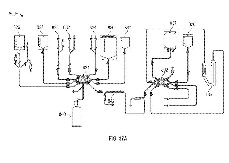
[00075] FIG. 37A is a schematic illustration of a disposable kit for
magnetic cell isolation,
for use with the processing apparatus and isolation module of FIG. 3, and
showing installation on
the processing apparatus and isolation module of FIG. 3.
[00076] FIG. 37B is a schematic illustration of the disposable kit for
magnetic cell
isolation of FIG. 37A, showing installation on the processing apparatus and
isolation module of
FIG. 3.
[00077] FIG. 38 is a flow chart illustrating a magnetic cell isolation
workflow/process
utilizing the disposable kit of FIGS. 37A and 37B on the processing apparatus
and isolation
module of FIG. 3.
[00078] FIG. 39 is a schematic illustration of a disposable kit for dosing
preparation/formulation, for use with the processing apparatus and isolation
module of FIG. 3.
11
CA 03204821 2023-06-08
WO 2022/132793 PCT/US2021/063342
[00079] FIG. 40 is a schematic illustration of the disposable kit for
dosing
preparation/formulation of FIG. 39, showing installation on the processing
apparatus and
isolation module of FIG. 3.
[00080] FIG. 41 is a flow chart illustrating a dosing preparation
workflow/process
utilizing the disposable kit of FIG. 39 on the processing apparatus and
isolation module of FIG.
3.
[00081] FIG. 42 is a perspective view of a bioprocessing system/apparatus
according to an
embodiment of the invention, showing a process drawer and cabinet in a closed
position.
[00082] FIG. 43 is another perspective view of the bioprocessing apparatus
of FIG. 42,
showing the cabinet in an open position.
[00083] FIG. 44 is a perspective view of the cabinet of the bioprocessing
apparatus of
FIG. 42, illustrating an extended position of vertical drawers thereof.
[00084] FIG. 45 is a front elevational view of the cabinet.
[00085] FIG. 46 is a perspective view of a housing and process drawer of
the
bioprocessing apparatus of FIG. 42, illustrating an open position of the
process drawer.
[00086] FIG. 47 is a top plan view of the process drawer of the
bioprocessing apparatus of
FIG. 42.
[00087] FIG. 48 is a perspective view of a pair of platform rocker
assemblies of the
process drawer according to an embodiment of the invention.
[00088] FIG. 49 is a perspective view of a waste drawer of the
bioprocessing apparatus of
FIG. 42.
[00089] FIG. 50 is a perspective view of a disposable bioprocessing kit
for use with the
bioprocessing apparatus of FIG. 42.
[00090] FIG. 51 is a rear, perspective view of a tray of the disposable
bioprocessing kit of
FIG. 50.
[00091] FIG. 52 is a perspective view of an anchor comb of the disposable
bioprocessing
kit of FIG. 50.
[00092] FIG. 53 is a front elevational view of the anchor comb of FIG. 52.
[00093] FIG. 54 is a perspective view of a tubing organizer of the
disposable
bioprocessing kit of FIG. 50.
12
CA 03204821 2023-06-08
WO 2022/132793 PCT/US2021/063342
[00094] FIG. 55 is a perspective view of a sampling card of the disposable
bioprocessing
kit of FIG. 50.
[00095] FIG. 56 is a front elevational view of the sampling card of FIG.
53.
[00096] FIG. 57 is a perspective view illustrating insertion of the tray
and culture vessels
of the disposable kit into the process drawer of the bioprocessing apparatus.
[00097] FIG. 58 is a side, cross-sectional view illustrating the tray and
culture vessels of
the disposable kit received in the processing drawer of the bioprocessing
apparatus.
[00098] FIG. 59 is a top view of the process drawer of the bioprocessing
apparatus,
showing various alignment features and sensors of the bioprocessing apparatus.
[00099] FIG. 60 is an enlarged, front perspective view of a peristaltic
pump assembly of
the bioprocessing apparatus, showing alignment and engagement features
thereof.
[000100] FIG. 61 is an enlarged, rear perspective view of a peristaltic
pump assembly of the
bioprocessing apparatus, showing alignment and engagement features thereof.
[000101] FIG. 62 is a an enlarged, perspective view of a linear actuator
array of the
bioprocessing apparatus, showing alignment and engagement features thereof.
[000102] FIG. 63 is a perspective, cross-sectional view of the process
drawer of the
bioprocessing apparatus.
[000103] FIG. 64 is an exploded, perspective view of a culture vessel of
the disposable
bioprocessing kit of FIG. 50.
[000104] FIG. 65 is a bottom plan view of the culture vessel of FIG. 64.
[000105] FIG. 66 is a perspective view of a portion of a rocking assembly
of the
bioprocessing apparatus of FIG. 42
[000106] FIG. 67 is another perspective view of the rocking assembly of
FIG. 66.
[000107] FIG. 68 is another perspective view of the rocking assembly of
FIG. 66,
illustrating engagement of the rocking assembly with a culture vessel.
[000108] FIG. 69 is a schematic diagram illustrating operation of the
rocking assembly of
FIG. 66.
[000109] FIG. 70 is a cross-sectional view of the process drawer of the
bioprocessing
apparatus of FIG. 42.
[000110] FIG. 71 is another cross-sectional view of the process drawer of
the bioprocessing
apparatus of FIG. 42, showing a recirculation air flow path.
13
CA 03204821 2023-06-08
WO 2022/132793 PCT/US2021/063342
[000111] FIG. 72 is another cross-sectional view of the process drawer of
the bioprocessing
apparatus of FIG. 42, showing a turbulent recirculation airflow at in
interface with culture
vessels.
[000112] FIG. 73 is a perspective, cross-sectional view of the tray of the
disposable
bioprocessing kit of FIG. 50, illustrating a recirculation air flow path.
[000113] FIG. 74 is a perspective, cross-sectional view of the process
drawer and tray of
the bioprocessing apparatus, illustrating the recirculation air flow path.
[000114] FIG. 75 is another perspective, cross-sectional view of the
process drawer and
tray of the bioprocessing apparatus, illustrating the recirculation air flow
path.
[000115] FIG. 76 is another perspective, cross-sectional view of the
process drawer and
tray of the bioprocessing apparatus, illustrating the recirculation air flow
path.
[000116] FIG. 77 is a rear, perspective view of a flow-through sensing
chamber of the
bioprocessing apparatus of FIG. 42, according to an embodiment of the
invention.
[000117] FIG. 78 is a front, perspective view of the flow-through sensing
chamber of FIG.
77.
[000118] FIG. 79 is a cross-sectional, perspective view of the flow-through
sensing
chamber of FIG. 77.
[000119] FIG. 80 is a perspective view of a back plate of the flow-through
sensing chamber
of FIG. 77.
[000120] FIG. 81 is an enlarged, perspective view of a backbone of the
disposable
bioprocessing kit of FIG. 50, illustrating the location of the flow-through
sensing chamber.
[000121] FIG. 82 is another enlarged, perspective view of a backbone of the
disposable
bioprocessing kit of FIG. 50, illustrating the location of the flow-through
sensing chamber.
[000122] FIG. 83 is a schematic illustration showing integration of the
flow-through
sensing chamber with various sensing devices.
[000123] FIG. 84 is another schematic illustration showing integration of
the flow-through
sensing chamber with various sensing devices.
[000124] FIG. 85 is a block diagram illustrating the fluid flow
architecture of the
bioprocessing apparatus of FIG. 42, according to an embodiment of the
invention.
[000125] FIG. 86 is a detail view of a portion of the block diagram of FIG.
85, illustrating a
first fluid assembly of the fluid flow architecture.
14
CA 03204821 2023-06-08
WO 2022/132793 PCT/US2021/063342
[000126] FIG. 87 is a detail view of a portion of the block diagram of FIG.
85, illustrating a
second fluid assembly of the fluid flow architecture.
[000127] FIG. 88 is a detail view of a portion of the block diagram of FIG.
85, illustrating a
sampling assembly of the fluid flow architecture.
[000128] FIG. 89 is a detail view of a portion of the block diagram of FIG.
85, illustrating a
filtration flow path of the fluid flow architecture.
[000129] FIG. 90 is a flowchart illustrating a method for bioprocessing
carried out using the
bioprocessing apparatus of FIG. 42, according to an embodiment of the
invention.
[000130] FIG. 91 is a flowchart illustrating a method for bioprocessing
carried out using the
bioprocessing apparatus of FIG. 42, according to an embodiment of the
invention..
[000131] FIG. 92 is a flowchart illustrating a method for bioprocessing
carried out using the
bioprocessing apparatus of FIG. 42, according to an embodiment of the
invention.
[000132] FIG. 93 is a block diagram illustrating the fluid flow
architecture of the
bioprocessing apparatus of FIG. 42, according to an embodiment of the
invention.
[000133] FIG. 94 is a block diagram illustrating the fluid flow
architecture of the
bioprocessing apparatus of FIG. 42, according to another embodiment of the
invention.
[000134] FIG. 95 is a block diagram illustrating the fluid flow
architecture of the
bioprocessing apparatus of FIG. 42, according to yet another embodiment of the
invention.
[000135] FIG. 96 is a block diagram illustrating the fluid flow
architecture of the
bioprocessing apparatus of FIG. 42, according to yet another embodiment of the
invention.
DETAILED DESCRIPTION
[000136] Reference will be made below in detail to exemplary embodiments of
the
invention, examples of which are illustrated in the accompanying drawings.
Wherever possible,
the same reference characters used throughout the drawings refer to the same
or like parts.
[000137] As used herein, the term "flexible" or "collapsible" refers to a
structure or
material that is pliable, or capable of being bent without breaking, and may
also refer to a
material that is compressible or expandable. An example of a flexible
structure is a bag formed
of polyethylene film. The terms "rigid" and "semi-rigid" are used herein
interchangeably to
describe structures that are "non-collapsible," that is to say structures that
do not fold, collapse,
or otherwise deform under normal forces to substantially reduce their elongate
dimension.
CA 03204821 2023-06-08
WO 2022/132793 PCT/US2021/063342
Depending on the context, "semi-rigid" can also denote a structure that is
more flexible than a
"rigid" element, e.g., a bendable tube or conduit, but still one that does not
collapse
longitudinally under normal conditions and forces.
[000138] A "vessel," as the term is used herein, means a flexible bag, a
flexible container, a
semi-rigid container, a rigid container, or a flexible or semi-rigid tubing,
as the case may be. The
term "vessel" as used herein is intended to encompass bioreactor vessels
having a wall or a
portion of a wall that is semi-rigid or rigid, as well as other containers or
conduits commonly
used in biological or biochemical processing, including, for example, cell
culture/purification
systems, mixing systems, media/buffer preparation systems, and
filtration/purification systems,
e.g., chromatography and tangential flow filter systems, and their associated
flow paths. As used
herein, the term "bag" means a flexible or semi-rigid container or vessel
used, for example, as
containment device for various fluids and/or media.
[000139] As used herein, "fluidly coupled" or "fluid communication" means
that the
components of the system are capable of receiving or transferring fluid
between the components.
The term fluid includes gases, liquids, or combinations thereof As used
herein, "electrical
communication" or "electrically coupled" means that certain components are
configured to
communicate with one another through direct or indirect signaling by way of
direct or indirect
electrical connections. As used herein, "operatively coupled" refers to a
connection, which may
be direct or indirect. The connection is not necessarily a mechanical
attachment.
[000140] As used herein, the term "tray" refers to any object, capable of
at least temporarily
supporting a plurality of components. The tray may be made of a variety of
suitable materials.
For example, the tray may be made of cost-effective materials suitable for
sterilization and
single-use disposable products.
[000141] As used herein, the term "functionally-closed system" refers to a
plurality of
components that make up a closed fluid path that may have inlet and outlet
ports, to add or
remove fluid or air from the system, without compromising the integrity of the
closed fluid path
(e.g. to maintain an internally sterile biomedical fluid path), whereby the
ports may comprise, for
example, filters or membranes at each port to maintain the sterile integrity
when fluids or air is
added or removed from the system. The components, depending on a given
embodiment, may
comprise but are not limited to, one or more conduits, valves (e.g. multiport
diverters), vessels,
receptacles, and ports.
16
CA 03204821 2023-06-08
WO 2022/132793 PCT/US2021/063342
[000142] Embodiments of the invention provide systems and methods for
manufacturing
cellular immunotherapies from a biological sample (e.g., blood, tissue, etc.).
In an embodiment,
a method includes genetically modifying a population of cells in a bioreactor
vessel to produce a
population of genetically modified cells, and expanding the population of
genetically modified
cells within the bioreactor vessel to generate a number of genetically
modified cells sufficient for
one or more doses for use in a cell therapy treatment without removing the
population of
genetically modified cells from the bioreactor vessel. In certain embodiments,
one or more of
the methods may include activating cells in the same bioreactor vessel using
magnetic or non-
magnetic beads to produce a population of activated cells prior to genetically
modifying the
cells, and washing the genetically modified cells on the bioreactor vessel to
remove unwanted
materials.
[000143] With reference to FIG. 1, a schematic illustration of a
bioprocessing system 10
according to an embodiment of the invention is illustrated. The bioprocessing
system 10 is
configured for use in the manufacture of cellular immunotherapies (e.g.,
autologous cellular
immunotherapies), where, for example, human blood, fluid, tissue, or cell
sample is collected,
and a cellular therapy is generated from or based on the collected sample. One
type of cellular
immunotherapy that can be manufactured using the bioprocessing system 10 is
chimeric antigen
receptor (CAR) T cell therapy, although other cellular therapies may also be
produced using the
system of the invention or aspects thereof without departing from the broader
aspects of the
invention. As illustrated in FIG. 1, the manufacture of a CAR T cell therapy
generally begins
with collection of a patient's blood and separation of the lymphocytes through
apheresis.
Collection/apheresis may take place in a clinical setting, and the apheresis
product is then sent to
a laboratory or manufacturing facility for production of CAR T-cells. In
particular, once the
apheresis product is received for processing, a desired cell population (e.g.,
white blood cells) is
enriched for or separated from the collected blood for manufacturing the
cellular therapy, and
target cells of interest are isolated from the initial cell mixture. The
target cells of interest are
then activated, genetically modified to specifically target and destroy tumor
cells, and expanded
to achieve a desired cell density. After expansion, the cells are harvested,
and a dose is
formulated. The formulation is often then cryopreserved and delivered to a
clinical setting for
thawing, preparation and, finally, infusion into the patient.
17
CA 03204821 2023-06-08
WO 2022/132793 PCT/US2021/063342
[000144] With further reference to FIG. 1, the bioprocessing system 10 of
the invention
includes a plurality of distinct modules or subsystems that are each
configured to carry out a
particular subset of manufacturing steps in a substantially automated,
functionally-closed and
scalable manner. In particular, the bioprocessing system 10 includes a first
module 100
configured to carry out the steps of enrichment and isolation, a second module
200 configured to
carry out the steps of activation, genetic modification and expansion, and a
third module 300
configured to carry out the step of harvesting the expanded cell population.
In an embodiment,
each module 100, 200, 300 may be communicatively coupled to a dedicated
controller (e.g., first
controller 110, second controller 210, and third controller 310,
respectively). The controllers
110, 210 and 310 are configured to provide substantially automated control
over the
manufacturing processes within each module. While the first module 100, second
module 200
and third module 300 are illustrated as including dedicated controllers for
controlling the
operation of each module, it is contemplated that a master control unit may be
utilized to provide
global control over the three modules. Each module 100, 200, 300 is designed
to work in concert
with the other modules to form a single, coherent bioprocessing system 10, as
discussed in detail
below.
[000145] By automating the processes within each module, product
consistency from each
module can be increased and costs associated with extensive manual
manipulations reduced. In
addition, as discussed in detail hereinafter, each module 100, 200, 300 is
substantially
functionally closed, which helps ensure patient safety by decreasing the risk
of outside
contamination, ensures regulatory compliance, and helps avoid the costs
associated with open
systems. Moreover, each module 100, 200, 300 is scalable, to support both
development at low
patient numbers and commercial manufacturing at high patient numbers.
[000146] With further reference to FIG. 1, the particular manner in which
the process steps
are compartmentalized in distinct modules that each provide for closed and
automated
bioprocessing allows for efficient utilization of capital equipment to an
extent heretofore not
seen in the art. As will be appreciated, the step of expanding the cell
population to achieve a
desired cell density prior to harvest and formulation is typically the most
time-consuming step in
the manufacturing process, while the enrichment and isolation steps, and the
harvesting and
formulation steps, as well as activation and genetic modification steps, are
much less time
consuming. Accordingly, attempts to automate the entire cell therapy
manufacturing process, in
18
CA 03204821 2023-06-08
WO 2022/132793
PCT/US2021/063342
addition to being logistically challenging, can exacerbate bottlenecks in the
process that hamper
workflow and decrease manufacturing efficiency. In particular, in a fully-
automated process,
while the steps of enrichment, isolation, activation and genetic modification
of cells can take
place rather quickly, expansion of the genetically modified cells takes place
very slowly.
Accordingly, manufacture of a cellular therapy from a first sample (e.g., the
blood of a first
patient) would progress quickly until the expansion step, which requires a
substantial amount of
time to achieve a desired cell density for harvest. With a fully automated
system, the entire
process/system would be monopolized by the expansion equipment performing
expansion of the
cells from the first sample, and processing of a second sample could not begin
until the entire
system was freed up for use. In this respect, with a fully-automated
bioprocessing system, the
entire system is essentially offline and unavailable for processing of a
second sample until the
entire cell therapy manufacturing process, from enrichment to
harvest/formulation is completed
on the first sample.
[000147]
Embodiments of the invention, however, allow for parallel processing of more
than one sample (from the same or different patients) to provide for more
efficient utilization of
capital resources. This advantage is a direct result of the particular manner
in which the process
steps are separated into the three modules 100, 200, 300, as alluded to above.
With particular
reference to FIG. 2, in an embodiment, a single first module 100 and/or a
single third module
300 can be utilized in conjunction with multiple second modules, e.g., second
modules 200a,
200b, 200c, in a bioprocessing system 12, to provide for parallel and
asynchronous processing of
multiple samples from the same or different patients. For example, a first
apheresis product from
a first patient may be enriched and isolated using the first module 100 to
produce a first
population of isolated target cells, and the first population of target cells
may then be transferred
to one of the second modules, e.g., module 200a, for activation, genetic
modification and
expansion under control of controller 210a. Once the first population of
target cells is
transferred out of the first module 100, the first module is again available
for use to process a
second apheresis product from, for example, a second patient. A second
population of target
cells produced in the first module 100 from the sample taken from the second
patient can then be
transferred to another second module, e.g., second module 200b, for
activation, genetic
modification and expansion under control of controller 201b.
19
CA 03204821 2023-06-08
WO 2022/132793 PCT/US2021/063342
[000148] Similarly, after the second population of target cells is
transferred out of the first
module 100, the first module is again available for use to process a third
apheresis product from,
for example, a third patient. A third target population of cells produced in
the first module 100
from the sample taken from the third patient can then be transferred to
another second module,
e.g., second module 200c, for activation, genetic modification and expansion
under control of
controller 201c. In this respect, expansion of, for example, CAR-T cells for a
first patient can
occur simultaneously with the expansion of CAR-T cells for a second patient, a
third patient, etc.
[000149] This approach also allows the post processing to occur
asynchronously as needed.
In other words, patient cells may not all grow at the same time. The cultures
may reach the final
density at different times, but the multiple second modules 200 are not
linked, and the third
module 300 can be used as needed. With the present invention, while samples
can be processed
in parallel, they do not have to be done in batches.
[000150] Harvesting of the expanded populations of cells from the second
modules 200a,
200b and 200c can likewise be accomplished using a single third module 300
when each
expanded populations of cells are ready for harvest.
[000151] Accordingly, by separating the steps of activation, genetic
modification and
expansion, which is the most time consuming, and which share certain
operational requirements
and/or require similar culture conditions, into a stand-alone, automated and
functionally-closed
module, the other system equipment that is utilized for enrichment, isolation,
harvest and
formulation is not tied up or offline while expansion of one population of
cells is carried out. As
a result, the manufacture of multiple cell therapies may be carried out
simultaneously,
maximizing equipment and floorspace usage and increasing overall process and
facility
efficiency. It is envisioned that additional second modules may be added to
the bioprocessing
system 10 to provide for the parallel processing of any number of cell
populations, as desired.
Accordingly, the bioprocessing system of the invention allows for plug-and-
play like
functionality, which enables a manufacturing facility to scale up or scale
down with ease.
[000152] In an embodiment, the first module 100 may be any system or device
capable of
producing, from an apheresis product taken from a patient, a target population
of enriched and
isolated cells for use in a biological process, such as the manufacture of
immunotherapies and
regenerative medicines. The third module 300 may be any system or device
capable of
harvesting and/or formulating CAR-T cells or other modified cells produced by
the second
CA 03204821 2023-06-08
WO 2022/132793 PCT/US2021/063342
module 200 for infusion into a patient, for use in cellular immunotherapies or
regenerative
medicine. In certain embodiments, the first module 100 and the third module
300 are similarly or
identically configured, such that the first module 100 may first be utilized
for enrichment and
isolation of cells (which are then transferred to the second module 200 for
activation,
transduction and expansion (and in some embodiments, harvesting)), and then
also used at the
end of the process for cell harvesting and/or formulation. In this respect, in
some embodiments,
the same equipment can be utilized for the front-end cell enrichment and
isolation steps, as well
as the back-end harvesting and/or formulation steps.
[000153] Referring now to FIG. 3, an exemplary configuration of the first
module 100 (and
in some embodiments, the third module 300) is illustrated. In an embodiment
the first module
100 (and third module 300) includes a processing apparatus 102 and an
isolation module 104. In
an embodiment, the processing apparatus 102 and the isolation module 104 may
be mechanically
interconnected with one another, such as via a bracket 105 mounted to the
respective bottoms of
the devices. The processing apparatus 102 may be, for example, a Sefia S-2000
cell processing
instrument, available from Cytiva. In an embodiment the processing apparatus
may be
configurated the same as, or substantially similar to, apparatus 900 disclosed
in WIPO
International Publication No. WO 2019/106207. The processing apparatus 102
thus includes a
base 106 that houses a centrifugal processing chamber 108, a high dynamic
range peristaltic
pump assembly 111, a stopcock manifold interface 112, and a heating-cooling-
mixing chamber
(thermal mixer) 114. As indicated below, the stopcock manifold interface 112
is configured to
receive a single-use, disposable kit specifically configured for performing
cell concentration,
platelet removal and density gradient-based separation, washing, and/or final
formulation, and
provides a simple and reliable means of interfacing multiple fluid or gas
lines together using, for
example, luer fittings. Within the base 106 is a motor drivingly connected to
a plurality (in this
case, four) of output shafts that are operable to move stopcocks of the
disposable kit between
open and closed positions under control of a controller. In an embodiment, the
pump assembly
111 is rated to provide flow rates as low as about 3 mL/min and as high as
about 150 mL/min).
The processing apparatus 102 may further include a suite of sensors configured
to monitor
various parameters of the apparatus 102, itself, and of various fluids handled
by the apparatus
102.
21
CA 03204821 2023-06-08
WO 2022/132793 PCT/US2021/063342
[000154] As further shown in FIG. 3, the processing apparatus 102 of the
first and/or third
module 100, 300 also includes a generally T-shaped hanger assembly 116 that
extends from the
base 106 and includes a plurality of hooks 118 for suspending a plurality of
bags for containing
or receiving fluids used in the bioprocessing operations carried out by the
first or third modules.
In an embodiment, there may be six hooks. Each hook may include an integrated
weight sensor
or load cell (not shown) for monitoring the weight of each vessel/bag. In an
embodiment, the
bags may be, for example, a sample source bag, a process bag, an isolation
buffer bag, a washing
bag, one or more storage bags, a post-isolation waste bag, a washing waste
bag, a media bag, a
release bag, and/or a collection bag, depending on the particular processes
being carried out. The
processing apparatus 102 also includes a centralized control unit, e.g.,
controller 110, for
carrying out one or more bioprocessing operations according to algorithm(s)
stored in memory in
an automated or semi-automated manner.
[000155] With further reference to FIG. 3, and with more specific reference
to FIGS. 4-11,
the isolation module 104 of the first and/or third module 100, 300 is shown.
The isolation
module 104 includes a base/housing 130, a stopcock manifold interface 132
located on the base
130 and configured to receive a stopcock manifold of a single use, disposable
cell processing kit,
and a vertical aperture or slot 134 in the base configured to removably
receive a magnetic cell
isolation holder 136 of the isolation module 104, the purpose of which will be
described
hereinafter. The isolation module 104 further includes a support pole 138
having one or more
hooks 140 or pegs for suspension of fluid bags or vessels therefrom. In an
embodiment, the
hook 140 may be configured with or connected to a load cell for real-time mass
monitoring of
the contents of the bag. While FIG. 3, illustrates the isolation module 104 as
having two hooks
140, more or fewer than two hooks may be present. For example, in an
embodiment, the
isolation module 104 has four hooks 140. In an embodiment, the inner surfaces
of the housing
130 and/or base structure thereof may be coated or covered with an
electrically conductive paint
or coating to shield from EMC perturbations, for example. In an embodiment,
the housing 130
may be manufactured from plastic, while the base structure that supports the
housing may be
metallic, although in certain embodiments, both the base structure and housing
may be formed
from plastic or similar non-conductive material.
[000156] In an embodiment the isolation module 104 includes a drip chamber
holder 113 to
insert and hold drip chamber of a disposable bioprocessing kit (e.g., for
washing, dosing
22
CA 03204821 2023-06-08
WO 2022/132793 PCT/US2021/063342
preparation, formulation and/or isolation of cells), as described hereinafter.
In an embodiment
the drip chamber holder can accommodate different diameters or shapes to be
compatible with
different versions of the disposable kit drip chamber, e.g., the drip chamber
380 of the kit 350
shown in FIG. 36, and/or the drip chamber 829 of kit 800 shown in FIGS. 37A
and 37B. In an
embodiment, the drip chamber holder may include one or several spring plungers
to improve the
grip on the drip chamber when inserted.
[000157] As best shown in FIG. 5-7, the stopcock manifold interface 132
includes one or
more latches or clamps 142, 143 that can be selectively deployed to retain a
cell processing kit in
position on the interface 132, as described hereinafter. The interface 132
further includes an
array of stopcock pins or splined output shafts 144 drivingly connected to at
least one stopcock
motor 146 housed within the base 130. In an embodiment, there are 6 output
shafts configured
to interface with a respective one stopcock of a 6 stopcock manifold of a
disposable cell
processing kit, although it is envisioned that more or fewer than 6 stopcock
pins may be utilized
without departing from the broader aspects of the invention, and depending on
the particular
configuration of the disposable kit. In an embodiment, each output shaft 144
has a dedicated
motor 146. The motors 146 are configured to rotate the output shafts 144 to
move stopcocks of
the disposable cell processing kit received on the interface 132 between open
and closed
positions under control of a controller, as described hereinafter. Notably,
the 6 stopcock
interface shown in FIG. 4 is capable of interfacing with a 4 or 6 stopcock
manifold of a
disposable cell processing kit.
[000158] With specific reference to FIGS. 4-6, 12 and 13, the isolation
module 104 may
include a plurality of sensors for monitoring various operational parameters
of the isolation
module 104, as well as parameters or conditions of flow lines and/or fluid
therein. For example,
in an embodiment, the isolation module 104 may include a line pressure sensor
assembly 148
having an interface beneath which a pressure sensor is positioned, and bubble
sensor/detector
assembly 150, both forming part of the stopcock manifold interface 132 for
monitoring a
pressure and the presence of bubbles, respectively, within one of more of the
fluid flow lines
connected to the module 104. As shown therein, the bubble sensor assembly 150
includes a
housing 152 having an upward facing channel 154 or passage therein, with which
the bubble
sensor is associated, and a cover 156 pivotally connected to the housing 152.
The channel 154 is
sized and dimensioned to receive a length of tubing, and the cover 156 is
selectively moveable
23
CA 03204821 2023-06-08
WO 2022/132793 PCT/US2021/063342
between an open and closed position with respect to the housing 152 to capture
and retain the
length of tubing within the channel 154. In an embodiment, the housing 152 and
cover 156 are
formed from a material having poor electrical conductivity, such as anodized
aluminum or
plastic, such that any electrical current present will pass through the
housing 130 of the isolation
module 104 and not the bubble sensor 150 (which could adversely affect
operation thereof). In
an embodiment, the housing 130 includes an air inlet having an integrated
filter through which
air may be drawn into the housing 130 for cooling the internal components
thereof during
operation.
[000159] With reference to FIGS. 10, 11 and 14-19, the isolation module 104
additionally
includes a magnetic field generator assembly 160 housed within the base
housing 130. In an
embodiment, the magnetic field generator assembly 160 includes a pair of
opposed permanent
magnets 162, 164 (having a space therebetween) mounted to a moveable carriage
166. While a
pair of magnets 162, 164 are illustrated, it is contemplated that for a same
final height, each
illustrated magnet 162 and 164 can either be made of a single long magnet, or
of a stack of
several shorter magnets without departing from the broader aspects of the
invention. As
described in detail below, the carriage 166 is moveable between an extended
position, where the
magnets 162, 164 are positioned on opposing sides of the slot 134 for
generating a magnetic field
within the slot 134, and a retracted position where the magnets 162, 164 are
moved rearwardly of
the slot 134 so as to not generate a magnetic field (or to only generate a
small or negligible
magnetic field) within the slot 134. The carriage 166 is slidably connected
to, and supported by,
upper and lower shafts 168, 170 received by bushings or bearings 172 in the
carriage assembly
166, and is operatively connected to a lead screw 174 that is received through
a central bushing
176 of the carriage 166. The lead screw 174 is rotatable to slidably move the
carriage 166
between its extended position and its retracted position, as disclosed in
detail hereinafter.
[000160] As best shown in FIGS. 14 and 16, the magnetic field generator
assembly 160
includes a motor 178 that is drivingly connected to the lead screw 174 via a
gearbox 180 and belt
182 (which links a timing pulley 183 of the gearbox 180 to a timing pulley 184
of the lead screw
174). The motor 178 is thus configured to rotate the lead screw 174 to extend
or retract the
carriage 166 and magnets 162, 164. As also shown therein, the magnetic field
generator
assembly 160 further includes an array of sensors that are utilized to detect
movement of the
carriage 166, the position of the carriage 166 (and thus magnets 162, 164),
and the presence of
24
CA 03204821 2023-06-08
WO 2022/132793 PCT/US2021/063342
the magnetic isolation holder 136 within the slot 134. For example, the
magnetic field generator
assembly 160 includes first and second sensors 186, 188 that are utilized to
detect and confirm
movement of the carriage 166, a third sensor 190 that is utilized to detect
the presence of the
magnetic cell isolation holder 136 within the slot 134 in the housing, and a
crank sensor 192. In
an embodiment, the sensors 186, 188, 190, 192 are inductive proximity sensors,
although other
types of sensors known in the art may also be utilized without departing from
broader aspects of
the invention. In connection with detection of the magnetic cell isolation
holder 136, the
magnetic field generator assembly 160 also includes a slidable locking pin 194
having a flange
196 (or washer) that is configured to engage a rear face of the carriage 166
adjacent to a top edge
thereof. The locking pin 194 also includes a coil spring 198 that is
configured to bias the locking
pin 194 towards the front of the isolation module 104 (i.e., towards the slot
134), the purpose of
which is hereinafter described.
[000161] Turning now to FIGS. 20-25, operation of the magnetic field
generator assembly
160 and positioning of the carriage 166 thereof will now be described. With
reference to FIG.
20, detection of the presence or absence of the magnetic cell isolation holder
136 within the slot
134, is carried out using the second sensor 188 and the third sensor 190. At
the beginning of the
process, the carriage 166 is in its retracted position where it is sensed by
sensor 188 and sensor
186. In this position, the locking pin 194 is in its retracted position (as it
is prevented sliding
forward due to engagement of the flange 196 with the rear of the carriage
166). In particular, the
carriage 166 holds the locking pin 194 in its retracted position against the
bias of the spring 198,
freeing the slot 134 for the magnetic cell isolation holder 136 to be
inserted.
[000162] As shown in FIG. 21, the magnet cell isolation holder 136 is now
inserted. When
the motor 178 rotates the lead screw 168, the carriage 166 is driven forward
towards the slot 134
and isolation holder 136. The locking pin 194 and flange 196 thereof move
forward along with
the carriage 166 due to the bias of the spring 198 which urges the locking pin
196 forward. As
shown therein, as the flange 196 or disc of the locking pin 194 is urged
forwardly, it is detected
by sensor 190 (and the first and second sensors also continue to detect the
presence of the
carriage 166). In this position, the distal end of the locking pin 194
contacts the magnetic cell
isolation holder 136 engaged with the slot 134.
[000163] As shown in FIG. 22, the carriage 166 is then driven to its
forward most position
by the motor 178 and lead screw 168 until the opposed magnets 162, 164 are
aligned with
CA 03204821 2023-06-08
WO 2022/132793 PCT/US2021/063342
opposing sides of the slot with slot 134. As shown therein, the locking pin
194 is prevented from
moving further forward due to its seated engagement with the inserted
isolation holder 136 (i.e.,
it contacts a seat in the isolation holder 136), and so the flange 196
continues to be detected by
the sensor 190. In this position, however, the carriage 166 is forward and
clear of the sensors
186, 188, and so the presence of the carriage 166 is not detected by these
sensors. As will be
appreciated, therefore, detection of the flange 196 by the sensor 190
indicates that the isolation
holder 136 is received in the slot 134, and the absence of a detection of the
carriage 166 by either
the first sensor 186 or second sensor 188 indicates that the carriage 166 and
magnets 162, 164
thereof are in the forward, working position where a magnetic field can be
generated within the
slot 134.
[000164] Turning now to FIG. 23, when the carriage 166 and magnets 162, 164
are moved
forward towards the extended position, but the isolation holder 136 is not
received within the slot
134 in the housing 130, the locking pin 194 is free to move forward with the
carriage 166 under
the bias of the spring 198 (i.e., its forward motion does not contact the seat
in the isolation holder
136). The locking pin 136 thus slides forward until its end bottoms out and
reaches the end of its
motion range. In this position, the distal end of the locking pin 194
obstructs the slot 134,
inhibiting insertion of the isolation holder 136, and the flange 196 is
forward of the sensor 190 so
that it is not detected thereby, indicating that the isolation holder 136 is
not present. As shown in
FIG. 23, the absence of the isolation holder 136 can be detected even when the
carriage is not in
its forward most position (i.e., sensor 186 detects the presence of the
carriage 166, which sensor
188 does not).
[000165] With reference to FIG. 24, and as indicated above, if the
isolation holder 136 is
inserted correctly within the slot 134, the locking pin 194 moves forward
along with the carriage
166 until it is seated within a recess or seat within the isolation holder
136. In this position, the
locking pin 194 prevents removal of the isolation holder 136 from the slot
134. As shown in
FIG. 25, however, if the isolation holder 136 is not properly positioned
within the slot 134, the
seat 199 within the isolation holder 136 is misaligned with the distal end of
the locking pin 194.
This misalignment prevents the locking pin 194 from entering the recess/seat
199. Accordingly,
the locking pin 194 is prevented from traveling far enough forward for the
flange 196 to be
aligned with the sensor 190. In this position, the sensor 188 does not detect
the carriage 166,
indicating that the carriage 166 has been moved forward. As the sensor 190
does not detect the
26
CA 03204821 2023-06-08
WO 2022/132793 PCT/US2021/063342
flange 196 of the locking pin 194 in this position of the carriage 166,
however, it indicates that
the isolation holder 136 is not properly received within the slot 134. Once in
the position shown
in FIG. 24, with the locking pin 194 holding the isolation holder 136 in place
within the slot 134,
and with the magnets 162, 164 aligned with the opposing sides of the slot 134,
a magnetic field
may be generated to capture bead-bound cells within the isolation holder 136
in a manner known
in the art and discussed in more detail hereinafter.
[000166] Referring once again to FIGS. 9, 11, 15 and 16, in an embodiment
the isolation
module 104 further includes a manual crank 171 that is operatively connected
to the linear screw
174. The crank 171 is operable to manually move the carriage 166 and magnets
162, 164 to the
retracted position in an emergency or in the event of a loss of electrical
power. The crank 171
has a pivotable handle that remains closed when not in use, but which can be
folded out when
needed. A ball detent screwed into the handle maintains the handle in the
closed position. In an
embodiment, the crank 171 may include a pawl and ratchet mechanism such that
when the crank
is closed, a pin separates a pawl from the ratchet due to the force of a
spring. In this position, the
crank is free to rotate, as the pawl and ratchet are not in contact. To open
the crank 171, an
operator must unfold the crank arm lever, which presses the pawl against the
rachet by the force
of the spring and by retreat of the pin. Since the pawl and ratchet are now in
contact, the crank
171 can be rotated to engage the lead screw 174 in a clockwise direction,
which corresponds to
rearward movement of the carriage 166. As alluded to above, sensor 192 is
provided to detect an
open position of the crank 171. In an embodiment, the crank 171 is configured
so that rotation in
the opposite direction is prevented, so that manual, forward movement of the
carriage 166 is not
possible (thereby preventing inadvertent or accidental activation of the
magnetic circuit).
[000167] Referring back to FIG. 9, the rear of the isolation module 104 may
include a
connector 151 for connection to a supply of electrical power for powering the
isolation module
104, a switch 153 for turning the isolation module 104 on and off, a
communications connector
155 for communicatively connecting the isolation module 104 to a controller,
and a plurality of
openings 157 through which an internal fan 159 may exhaust air to keep the
isolation module
104 at an optimal working temperature. In an embodiment, the communications
connector 155
may be a USB connector, although other wired or wireless communication means
known in the
art may also be utilized. In an embodiment, the isolation module 104 is
communicatively
coupled to the processing apparatus 102 and controlled by the controller 110
thereof In this
27
CA 03204821 2023-06-08
WO 2022/132793 PCT/US2021/063342
respect, all the information obtained by the various sensors of the isolation
module 104 (e.g.,
regarding the position and status of the magnetic field generator assembly
160, cell processing
kit on the interface 132, and/or parameters of the fluid passing through
various flow lines, etc.) is
communicated to the controller of the processing apparatus 102 where it is
analyzed and then
utilized by the controller to control operation of the isolation module 104,
generate alerts and the
like. Accordingly, the isolation module 104 need not be outfitted with a
separate processor and
memory, which increases cost and complexity.
[000168] In connection with operation of the isolation module 104, the
front of the isolation
module 104, as shown in FIG. 4 may include an array of indicator lights for
conveying to an
operator a status/position of the magnetic field generator assembly. For
example, the indicator
lights 161 may include a green indicator light indicating the carriage 166 and
magnets 162, 164
are in their retracted position, a blinking yellow indicator light indicating
that the carriage 166 is
moving, and a solid yellow indicator light indicating that the carriage and
magnets are in their
extended positions for magnetic retention of bead-bound cells passing through
the isolation
holder 136. In another embodiment, the front of the isolation module 104 may
instead, or in
addition, include pictograms including, for example, a first pictogram that,
when illuminated,
indicates that the isolation holder 136 can be inserted into the slot 134 in
the isolation module
104, a second pictogram that, when illuminated indicates that the
application/process has been
successfully completed and the magnetic circuit is off (and that the isolation
holder 136 can be
removed from the isolation module 104), and a third pictogram in the form of a
lock or other
icon that, when illuminated, indicates that the isolation holder 136 is
properly locked in place.
[000169] As discussed in detail hereinafter, the isolation module 104
provides for an
expanded array of bioprocessing functions to be carried out in a single, easy
to use system.
These processes may include, for example, enrichment and magnetic isolation of
cells, washing,
as well as dosing preparation including cell harvesting and final formulation.
As is known in the
art, magnetic particle-based cell selection or isolation involves isolating
certain cells from a cell
mixture via targeted binding of cell surface molecules to antibodies or
ligands of magnetic
particles (e.g., beads). Once bound, the cells coupled to the magnetic
particles are able to be
separated from the unbound population of cells. For example, the cell mixture
including the
bound and unbound cells may be passed through a separation column positioned
within a
magnetic field generator (e.g., magnetic field generator assembly 160 of the
isolation module
28
CA 03204821 2023-06-08
WO 2022/132793 PCT/US2021/063342
104) that captures the magnetic particles and, therefore, the associated bound
cells. The unbound
cells pass through the column without being captured. In embodiments, the
magnetic cell
isolation holder 136 and/or the isolation module 104 may be specifically
configured for cell
enrichment and isolation using various magnetic isolation bead types
(including, for example,
Miltenyi beads, Dynabeads and StemCell EasySep beads). Exemplary
configurations of the
isolation holder 136 are provided below.
[000170] As indicated above, the magnetic cell isolation holder 136 may be
designed and
configured for use with a variety of different magnetic bead sizes and types.
For example, in an
embodiment, the magnetic cell isolation holder 136 may be specifically
designed for use with
nano-sized magnetic beads such as, for example, Miltenyi beads. With reference
to FIGS. 26-29,
in an embodiment, the magnetic cell isolation holder 136 of the isolation
module 104 may
include a body portion 274 that that receives and retains therein a vertical
column 280, and a
handle 276 connected to the body portion 174 allowing for easy manipulation by
a user (e.g., to
install and remove the isolation holder 136 from the slot 134 in the isolation
module 104). In an
embodiment, the body portion 274 and handle portion 276 are integral, and may
be formed from
molded halves 277, 278 that sandwich the column 280. As best shown in FIG. 26,
the recess 199
for receiving the locking pin 194 of the magnetic field generator assembly 160
is formed in a
forward face of the body portion 274. With reference to FIGS. 28 and 29, in
one exemplary
embodiment, the column shell may be a stock extruded aluminum shell, anodized
and further
machined as necessary for dimensional tolerances. The column 280 has a pair of
identical
endcaps 282 connected to the column 280 at opposed ends thereof, each
including a female glue
port for interfacing directly to lengths of PVC tubing 284, 286, an 0-ring
(for forming a fluidic
seal) and a heat-sealed-on piece of mesh (useful in process to retain the
beads before the
encapsulant is added). In an embodiment, the column is filled with a magnetic
retention element
which, in an embodiment, in array of ferromagnetic spheres or beads, and an
encapsulant. The
encapsulant utilized may be a biocompatible epoxy. To apply the encapsulant,
the column is
filled with ferromagnetic spheres or beads, the encapsulant is added to fully
wet the beads, and
then the excess encapsulant is removed via centrifugation and the encapsulant
is cured.
[000171] As best illustrated in FIGS. 26 and 27, the first length of PVC
tubing 284 enters
the upper end of the column 280 vertically from above, and forms an inlet flow
passage for bead-
bound cells into the column 280 when the isolation holder 136 is received
within the slot 134 of
29
CA 03204821 2023-06-08
WO 2022/132793 PCT/US2021/063342
the isolation module 104. The second length of PVC tubing 286 exits the lower
end of the
column 280, providing for an exit pathway of fluid from the column 280 while
the bead-bound
cells are retained within the column, as known in the art. The second length
of PVC tubing 286,
in an embodiment, is routed through the handle 276 where is exits the
isolation holder 136
vertically. While note illustrated, the first and second lengths of tubing
284, 286 include
connectors for integration of the column 280 with a flow pathway of a magnetic
cell isolation kit
or cassette received on the interface 132 of the isolation module, as
described hereinafter. FIG.
30 illustrates installation of the magnetic cell isolation holder 136 into the
slot 134 in the
isolation module (i.e., by sliding it into the slot 134 from above). Removal
of the magnetic cell
isolation holder 136 is carried out by sliding the holder upwardly within the
slot 134.
[000172] Turning now to FIGS. 31-35, various other exemplary configurations
of the
magnetic cell isolation holder 136 for use with the isolation module 104 are
illustrated. As
disclosed above, certain magnetic cell isolation techniques may incorporate
nano-sized particles
(e.g., beads of about 50 nm or less in diameter) while other techniques may
use larger particles
(e.g., beads of about 2 [tm or more in diameter). For example, smaller
particles may be desirable
because smaller particle sizes may avoid receptor activation on the target
cells. Further,
downstream steps may skip particle removal, because the nano-sized particles
may have little
effect on downstream processing or cell function. However, the smaller nano-
sized magnetic
particles may be separated using a magnetic cell isolation procedure that
involves the use of a
magnetic field gradient intensifier to amplify an applied magnetic field
gradient. In contrast,
larger particles have a higher magnetic moment. Thus, isolation of certain
larger particles may
not involve a magnetic field gradient intensifier. However, with larger
particles, the isolation
column within the magnetic field generator may reach capacity before a
sufficient number of
bead-bound cells are captured. In particular, the bead-bound cells accumulate
on the inside of
the passage to a point where additional bead-bound cells to be captured are no
longer in a region
with a high enough gradient to overcome the viscous drag forces urging them
through the
passage. Accordingly, using larger particles may necessitate multiple capture
and elution cycles
to obtain a desired yield, which adds complexity to magnetic particle-based
cell isolation
techniques. As disclosed hereinafter, certain configurations of the magnetic
cell isolation holder
may obviate the need for multiple cycles to be carried out, namely, by passing
the cell mixture
through a non-linear flow path within the magnetic field, circulating the cell
mixture through or
CA 03204821 2023-06-08
WO 2022/132793 PCT/US2021/063342
within the magnetic field, and/or making multiple passes through the magnetic
field. As used
herein, non-linear means not in a straight line through the magnetic field.
For example, the flow
path may be spirally or helically shaped, or may have one or more curves or
contours within the
magnetic field.
[000173] As shown in FIGS. 31-33, a magnetic cell isolation holder 250 for
use with the
isolation module 104 is shown coupled to the magnetic field generator assembly
160 (i.e.,
received between the magnets 162, 164 of the magnetic field generator assembly
160). As
alluded to above, the magnetic field generator 160 is configured to generate a
magnetic field
within the slot 134 (also referred to herein as receiving area 134). The
receiving area 134 and
the magnetic field have a major axis (defining the longitudinal extent of the
magnetic field) and a
minor axis, whereby the gradient and field strength is substantially constant
along lines parallel
to the major axis (and may decrease at the extremities of the major axis).
Looking at a cross-
sectional area perpendicular to the major axis (see, e.g., FIG 32), the
gradient is substantially
constant along lines running into and out of the page.
[000174] The magnetic cell isolation holder 250 is configured for removable
coupling with
the magnetic field generator 160, e.g., received within receiving area/slot
134 of the magnetic
field generator 160. As illustrated in FIGS. 31 and 32, in an embodiment, the
magnetic cell
isolation holder 250 includes a body 252, which may be formed from any
suitable nonmagnetic
material configured to accommodate the cell isolation and be coupled to the
magnetic field
generator 160. In an embodiment, the body 252 is generally rectangular in
shape, having a
longitudinal extent along the major axis of the magnetic field (in the
vertical direction in FIG.
31) that is greater than a width or thickness of the body, and includes a
plurality of channels or
races 254 that extend along the body 252 for receiving and retaining a tube
256. The tube 256,
for its part, may be configured to, under the magnetic field, retain cells
bound to magnetic
particles and permit unbound cells to pass through, as is known in the art.
For example, the
magnetic particles may be Dynabeads or SCT beads, although other magnetic
particle/bead types
may be utilized without departing from the broader aspects of the invention.
[000175] The tube 256 is routed along and/or through the body 252 via the
races 254 and
defines a flow passage for the flow of a fluid (e.g., a cell mixture). The
races 254 and tube 256
are positioned such that the flow passage defined by the tube 256 is
positioned within the
magnetic field when the magnetic cell isolation holder 250 is coupled to the
magnetic field
31
CA 03204821 2023-06-08
WO 2022/132793 PCT/US2021/063342
generator 160 (i.e., received within slot 134). Moreover, the races 254, and
thus the tube 356
and the flow passage defined thereby, are configured such that, when the
magnetic cell isolation
holder 250 is coupled to the magnetic field generator 160, a direction of
fluid flow within the
flow passage (i.e., through the tube) at a first location within the magnetic
field is different than a
direction of fluid flow within the flow passage at a second location within
the magnetic field, as
discussed hereinafter.
[000176] For example, as illustrated in FIGS. 31-33, in an embodiment, the
body 252 may
include eight generally vertical channels or races 254, two adjacent to each
longitudinal corner of
the body 252. The tube 256 is routed through the races 254 in a manner so as
to form a plurality
of serially and fluidly interconnected loops. Where the body contains eight
races 254, four serial
loops are formed by routing the tube 256 through the races 254. It is
contemplated that the body
252 may be formed with more or fewer than eight races so as to accommodate
more or fewer
than four loops, as desired. The positioning of the tube 256 into loops
provides for increased
residence time of the cell mixture within the magnetic field (the total time
the cell mixture passes
through the high gradient magnetic field) without reducing the flow velocity
(by reducing flow
rate or enlarging the cross-sectional area of the flow passage), thus enabling
better capture of the
bead-bound cells as compared to a single, vertical pass through the magnetic
field (at the same
flow velocity and same longitudinal length of the magnetic field generator).
[000177] FIG. 32 more clearly shows the tube loops of the magnetic cell
isolation holder
250. As shown therein, the plurality of loops of tube each include a first
portion 258 extending
substantially linearly along the longitudinal extent of the body 252, wherein
the longitudinal
extent of the body 252 aligns with the major axis of the magnets 162, 164 and
magnetic field that
has substantially constant gradients along lines parallel to the major axis of
the magnet and thus
parallel (and ultimately colinear) to the tubing pathways running along the
longitudinal axis of
the holder. The loops of tube further include a second portion 260 extending
from the first
portion 258 and forming a first return bend, a third portion 262 extending
substantially linearly
and parallel to the first portion 258, and a fourth portion 264 extending from
the second portion
and forming a second return bend. As indicated above, the loops are serially
connected to one
another such that the fourth portion/bend 264 of a first loop of the plurality
of loops is fluidly
connected to the first portion 258 of a second loop to provide fluid
interconnection of the first
loop with the second loop for circulation of the fluid between the loops
within the magnetic field.
32
CA 03204821 2023-06-08
WO 2022/132793 PCT/US2021/063342
Fluid in one of the loops, for example, first passes through the generally
vertical first portion
258, enters the first return bend 260, and then passes into the generally
vertical third portion 262.
The fluid then passes into the fourth portion/bend 264 and into a next
downstream loop. In an
embodiment, the first return bend 260 and the second return bend 264 are bends
of
approximately 180 degrees such that fluid flow in the first portion 258 and
the third portion 262
are generally parallel but in opposite directions, respectively. While not
illustrated, the tube 256
has an inlet end for connection to, and for receiving a cell mixture from, a
source (e.g., process
bag), as well as an outlet end for selective connection to a waste bag and/or
collection bag. The
plurality of loops of tube 256 are intermediate the inlet end and outlet end.
In some
embodiments, the flow passage may have an even number of lengths (e.g.,
vertical portions) such
that the inlet and outlet are on the same end of the magnetic cell isolation
holder 250. In other
embodiments, the flow passage may have an odd number of vertical portions so
that the inlet and
outlet are located on opposing ends of the magnetic cell isolation holder 250.
[000178] In an embodiment, the magnetic cell isolation holder 250 may
include a handle
266 or finger grip portion enabling a user to grasp the magnetic cell
isolation holder 250 to
position it within, or remove it from, the receiving area 134. As best
illustrated in FIG. 31, the
magnetic cell isolation holder 250 is inserted between the magnetic field
plates 162, 164 of the
magnetic field generator 160. For example, the position of races 254, and thus
the longitudinal
passes 258, 262 of tube 256 within the magnetic field generator 160 may cover
the location in
the magnetic field with the highest magnetic field strength. In another
example, the position of
races 254, and thus the vertical passes 258, 262 of tube 256 within the
magnetic field generator
160 may cover the location in the magnetic field with the highest magnetic
field gradient, while
meeting a magnetic field strength requirement of the magnetic particles. FIG.
33 illustrates the
position of the vertical passes of tube 256 within the magnetic field when the
magnetic cell
isolation holder 250 is received in the slot 134 between the magnets 162, 164.
As illustrated
therein, the body 252 of the magnetic cell isolation holder 250, and the
location of the races 254,
as well as the magnets 162, 164, are configured and dimensioned such that the
vertical passes of
tube 256 are positioned within the high gradient regions 268 of the magnetic
field generator 160
when the magnetic cell isolation holder 302 is coupled to the magnetic field
generator 350.
[000179] Turning now to FIG. 34, in an embodiment, the magnetic cell
isolation holder 300
may include a ferromagnetic core 270 that extends substantially the entire
length of the magnetic
33
CA 03204821 2023-06-08
WO 2022/132793 PCT/US2021/063342
field, and which is encircled by the tube 256. In an embodiment, the
ferromagnetic core 270
may be an integral part of the body 252 of the isolation holder 250, or it may
be an additional
component. The use of a ferromagnetic core 270 allows higher gradients to be
produced over a
longer length as compared to systems without a ferromagnetic core. In
particular, the
ferromagnetic core creates additional parallel high gradient regions along the
longitudinal axis of
magnetic plates, thereby allowing for a longer length of tubing to be routed
within the same
magnet field volume as compared to not having the ferromagnetic core. In an
embodiment, the
ferromagnetic core 270 may be formed from a variety of ferromagnetic materials
such as, for
example, iron.
[000180] FIG. 35 is a simplified illustration of another configuration for
the magnetic cell
isolation holder according to another embodiment of the invention. As
illustrated therein, rather
than the tube 256 being formed into a plurality of longitudinal loops, the
tube 256 is wound or
wrapped in a substantially spiral or helical configuration. As shown, the
plurality of loops 272
extend in a direction substantially perpendicular to the longitudinal
direction, such that a flow
through each loop 272 is generally perpendicular to the longitudinal direction
within the
magnetic field (e.g., horizontal, rather than vertical). Similar to the
configuration of the tube
shown in FIGS. 31-31, the plurality of loops 272 within the magnetic field
provide a longer
length of travel for a fluid within the flow passage of the tube 256 as
compared to a single
column that extends linearly through the magnetic field. In an embodiment, the
horizontal or
spiral loops 272 of tube 256 may encircle a ferromagnetic core 278.
[000181] While FIGS. 31-35 illustrate the tube 306 arranged in
substantially vertically- and
horizontally-extending loops (i.e., parallel to or perpendicular to the
longitudinal direction/major
axis of the magnetic plates and receiving area), respectively, it is
contemplated that the tube may
be arranged in any configuration that provides a flow passage of increased
length/distance within
the magnetic field generated by the magnetic field generator as compared to a
single, linear
passage through the magnetic field. This may be accomplished through the use
of multiple loops
of any orientation/direction (so that the cell mixture makes multiple passes
through the magnetic
field), and/or through the use of a single or multiple non-linear passes
through the magnetic field
(e.g., the tubing has curved or arcuate portions within the magnetic field).
[000182] In an embodiment, the tubing may be arranged to form a plurality
of loops
wherein the tubing loops around the outside of the receiving area 134 (i.e.,
outside of the
34
CA 03204821 2023-06-08
WO 2022/132793 PCT/US2021/063342
magnetic field) so that all flows within the magnetic field area are all
running in the same
direction (e.g., from top to bottom or bottom to top). Moreover, it is
contemplated that all of the
tube in the magnetic field may run in the same direction, and the system may
include a manifold
at the top and a manifold at the bottom to allow for parallel flow.
[000183] Still further, it is contemplated that the magnetic isolation
holder may be
configured with a flow passage/tube that diverts into multiple passages
through the magnetic
field, and which reconverge. Moreover, in an embodiment, the body 252 of the
magnetic cell
isolation holder 250 may be configured as a fluidic device having an integral
flow passage(s)
(i.e., without necessitating a separate tube 256). In particular, it is
contemplated that the flow
passage and/or ferromagnetic core may be manufactured entirely out of metal.
This would allow
one to take further advantage of the higher gradient regions of the magnetic
field. In yet another
embodiment, it is contemplated that the flow passages may be injection molded
into an insert. It
is contemplated that one could insert mold with a metal framework to add more
gradient regions.
Similarly, it is contemplated that one could additively manufacture/print the
flow passages out of
a suitable non-ferrous material (e.g., plastic or the like).
[000184] While it has been hereinbefore disclosed that the magnetic field
generator may be
comprised of two opposed magnetic plates that form permanent magnets, the
invention is not so
limited in this regard. In particular, it is contemplated that the magnetic
field generator may be
an electromagnet that generates a field that is substantially similar to a
field created by
permanent magnets.
[000185] As disclosed above, the processing apparatus 102 and isolation
module 104 are
intended to be used in combination with one another to carry out, in an
automated or semi-
automated manner, a variety of functions, protocols and/or workflows
associated with isolation,
harvesting and final formulation of cellular products. In particular, the
processing apparatus 102
and isolation module 104 can be controlled so as to carry out various
operations associated with
these processes in sequence, with minimal or no human intervention, according
to a set of
instructions executed by the controller (e.g., controller 110 or 310) of the
processing apparatus
102 and stored in memory of the processing apparatus 102. In an embodiment,
the processing
apparatus 102 is configured and operable to carry out any of the protocols set
forth in WIPO
International Publication No. WO 2019/106207 and carried out by the apparatus
900 disclosed
therein, with the isolation module 104 providing additional functionality and
possible workflows,
CA 03204821 2023-06-08
WO 2022/132793 PCT/US2021/063342
as described below. Indeed, the processing apparatus 102 and isolation module,
as disclosed
above and described in more detail below, provide for fluid management,
centrifugation,
temperature control, cell isolation, cell washing, cell concentration, cell
preparation and
formulation, for example.
[000186] In connection with the processing apparatus 102 and insolation
module 104,
embodiments of the invention provide a variety of single use,
disposable/consumable kits that are
designed for use with the processing apparatus 102 and/or isolation module 104
for assisting
with the carrying out processes and/or workflows associated with isolation,
harvesting and final
formulation of cellular products. With reference to FIG. 36, a disposable
washing kit 350 for use
with the processing apparatus 102 is shown. The washing kit 350 is a single-
use, disposable kit
that is utilized in conjunction with the apparatus 102 to wash and concentrate
a fresh or thawed
input product after an optional, temperature-controlled initial dilution. As
shown in FIG. 36, the
kit 350 includes a cassette or manifold 352 having four stopcocks 354, 356,
358, 360, an input
line 362 fluidly connected to stopcock 354, a final product/collection
container or bag 364
fluidly connected to stopcock 356 via line 366, a washing solution line 368
and a resuspension
solution line 370 fluidly connected to stopcock 358 via line 372, and a waste
container or bag
374 fluidly connected to the stopcock 360 via line 376. As shown therein, the
input line 362,
washing solution line 368 and resuspension solution line 370 may be outfitted
with end caps 378
the preserve the sterility of the lines during transport and storage, and
which can be removed or
cut off just prior to use so that bags containing a fresh/thawed input
product, wash solution, and
resuspension solution, respectively, can be connected to the lines via any
means known in the art,
such as sterile welding or the like.
[000187] As further shown in FIG. 36, the input line 362 includes an in-
line drip chamber
380 having an integral filter. The kit 350 further includes a separation
chamber 382 fluidly
connected to the cassette 352 via flow line 384, and a branch tubing tail 386
fluidly connected to
the cassette 352 via line 384. The tubing tail 386 and a second tubing tail
connected to the
stopcock 358 of the cassette are outfitted with hydrophobic filters 388. In an
embodiment, the
hydrophobic filters are 2 micrometer hydrophobic filters. In an embodiment,
the kit 250 may be
sterilized by means known in the art such as, for example, ethylene oxide
sterilization, and sealed
in a blister pack for transport to an end user and for storage.
36
CA 03204821 2023-06-08
WO 2022/132793 PCT/US2021/063342
[000188] In use, the manifold 352 is installed on the stopcock manifold
interface 112 of the
processing apparatus 102 such that respective motor output shafts of the
interface 112 are
engaged with a respective one of the four stopcocks 354, 356, 358, 360 for
controlling a position
of the stopcocks. The separation chamber 382 is received within the
centrifugal processing
chamber 108. The input line 362 is connected to a bag containing an input
product to be washed,
the washing solution line 372 connected to a bag containing washing solution,
and the
resuspension solution line 370 connected to a bag containing resuspension
solution, and these
bags, along with the waste bag 374 and collection bag 364, are suspended from
the hooks 118 of
the processing apparatus 102. The washing and optional concentration processes
are then carried
out according to a preprogrammed set of instructions stored in memory and
utilized by controller
110 of processing apparatus 102. In an embodiment, a washing process utilizing
processing
apparatus 102 and disposable kit 350 includes, optionally, initial dilution of
the input product,
concentrating the input product (so as to reduce its volume), washing the
input product, and then
resuspending the input product and collecting the resuspended input product in
the collection
bag.
[000189] During the initial dilution step, parameters such as temperature,
post-dilution
mixing, dilution mix time and dilution mix rate can be input or retrieved from
memory, and the
washing solution from the bag connected to washing solution line 372 is
utilized to perform the
initial dilution. During the concentration/volume reduction step, parameters
such as priming (or
not) of the flow line(s) with input product, input bag rinsing during the last
volume reduction
cycle, input bag rinsing volume, and input bag manual mixing (during the
middle of the input
bag rinsing step) can be selected and/or entered, and/or enabled or disabled.
Moreover, the
number of washing cycles performed during the washing phase can be input and
selected.
Finally, during the resuspension phase, a prompt instructing the user to
switch washing and
resuspension clamps after the washing phase can be enabled or disabled, and
the volume of the
final product at the end of the resuspension phase can be input and/or
selected. In an
embodiment, the washing process carried out utilizing the processing apparatus
102 and kit 350
can be utilized to wash and concentrate an input product before and/or after
activation,
transduction and expansion.
[000190] In an embodiment, the processing apparatus 102, isolation module
104 and kit
350 allow for accurate, small final product volumes to be achieved during
resuspension using an
37
CA 03204821 2023-06-08
WO 2022/132793 PCT/US2021/063342
algorithm to control filling of resuspension media into the separation chamber
382, in order to
avoid overshooting the volume. A method of resuspending the intermediate
volume to achieve a
desired final volume is carried out simultaneously with a rinsing of the
separation chamber of
cellular products, and includes, at a first step, extracting the contents of
the separation chamber
intermediate volume into the final bag line, at a second step, calculating of
the number of rinsing
cycles and associated filling volumes required to reach the final volume, at a
third step, filling of
the separation chamber 382 until 10 mL from the rinsing cycle volume final
target is achieved, at
a fourth step, incrementally filling of 1 mL volume increments with a 2 second
pause between
increments until the target rinsing cycle volume is reached, at a fifth step,
extracting the rinsing
volume toward the final/collection bag, and repeating steps three through five
until the number
of rinsing cycles is completed and the final volume of the output bag is
reached. During
extraction of the rinsing volume toward the final bag, air intake during the
filling step is
accounted and the filling volume of the next rinsing cycle subsequently
adjusted to ensure the
total final volume is effectively reaching the target value. It is
contemplated that the general
process steps disclosed above may be modified as desired such that, for
example, the initial
filling of the separation chamber is carried out to any desired volume, and
then the separation
chamber is incrementally filled with any desired smaller increment volumes,
with a pause of a
selected duration taking place between smaller volume increments (i.e., the
volumes and pause
durations specified above may be modified, as desired).
[000191] With reference to FIGS. 37A and 37B, a single-use, disposable
magnetic cell
isolation kit 800 for use with the processing apparatus 102 and isolation
module 104 is shown
(FIG. 37B more clearly showing placement of the various components on the
processing
apparatus 102 and isolation module 104, respectively). The magnetic cell
isolation kit 800 and
associated protocols enabled by the use of such kit, under control of the
controller 110 of the
processing apparatus 100, allows for initial dilution, volume reduction,
washing, incubation,
post-incubation wash, magnetic isolation and final resuspension of a cell
population, as disclosed
hereinafter. In an embodiment, the magnetic cell isolation kit 800 includes a
cassette or
manifold 802 having four stopcocks 804, 806, 808, 810. The kit 800 also
includes a line 811
fluidly connected to the first stopcock 804 and configured for fluid
connection to a fitting on the
magnetic cell isolation holder 136, a line 812 fluidly connected to the second
stopcock 806 and
configured for fluid connection to a second fitting on the magnetic cell
isolation holder 136, a
38
CA 03204821 2023-06-08
WO 2022/132793 PCT/US2021/063342
collection bag 813 fluidly connected to the fourth stopcock 810 via line 814,
a tubing tail 815
fluidly connected to the third stopcock 808 for fluid connection to a
resuspension buffer bag (not
shown) containing a suspension medium used to resuspend the positive fraction
of cells after
bead isolation, and a tubing tail 816 fluidly connected to the third stopcock
808 for fluid
connection to a bag (not shown) containing a release buffer used to release
the cells from the
magnetic beads within the magnetic cell isolation holder 136. As further shown
in FIGS. 37A
and 37B, the magnetic cell isolation kit 800 additionally includes a pair of
tubing tails 817, 818
fluidly connected to the second and fourth stopcocks 804, 810, respectively,
and outfitted with
hydrophobic filters of the type hereinbefore described. The kit 800 also
includes a negative
fraction bag 820 fluidly connected to the first stopcock 804 via a line 819.
As shown in FIG.
37A, the manifold 802 is configured for installation on the manifold interface
132 of the isolation
module 104.
[000192] With further reference to FIGS. 37A and 37B, the kit 800 further
includes a
second manifold 821 having four stopcocks 822, 823, 824, 825, and configured
to be received on
the manifold interface 112 of the processing apparatus 102. The kit 800
additionally includes a
final collection/transfer bag 826 fluidly connected to the second stopcock
823, a process
bag/incubation bag 827 likewise fluidly connected to the second stopcock 823,
a line 828 fluidly
connected to the first stopcock 822 and having an in-line drip chamber 829
with a 200
micrometer filter. The line 828 additionally includes a branch line 830 having
a tubing tail, and
a branch line 831 having a sampling pillow. As illustrated, the kit 800
further includes a line 832
fluidly connected to the first stopcock 822 for connection to a platelet-free
buffer bag used for
platelet depletion. Line 832 includes a branch line 833 having a filter. The
kit 800 also includes
line 834 fluidly connected to the fourth stopcock 825, and having a branch
line 835 having a
filter. The line 834 is configured for fluid connection to a bag containing
isolation buffer used to
perform washing cycles during bead incubation and optional post-incubation
wash cycles for
removing excess beads. As illustrated, the kit 800 includes a waste bag 836
fluidly connected to
the fourth stopcock 825, and a spare bag 837 (that is not used during the
isolation process)
fluidly connected to the third stopcock 824. Certain of the lines are
outfitted with sampling
pillows 838 and/or filters 839, as illustrated. Still further, the kit 800
includes a separation
chamber 840 configured to be received in the centrifugal processing chamber
108 of the
processing apparatus 102. Line 841 interconnects the manifold 802 on the
isolation module 104
39
CA 03204821 2023-06-08
WO 2022/132793 PCT/US2021/063342
with the manifold 821 on the processing apparatus 102 for fluid flow
therebetween, and includes
a section of peristaltic pump tubing 842 configured to engage the peristaltic
pump assembly 111
of the processing apparatus 102, and a drip chamber 843. The kit 800
additionally includes
further tubing tails having sterile air filters 844. A line 845 is also
fluidly connected to the third
stopcock 824 an opposite end of which is configured for fluid connection to
the bottom port in a
process bag 846, which also forms a part of disposable kit 800. In an
embodiment, the kit 800
may be sterilized by means known in the art such as, for example, ethylene
oxide sterilization,
and sealed in a blister pack for transport to an end user and for storage.
[000193] Turning now to FIG. 38 an exemplary protocol 850 for magnetic
isolation of cells
using magnet cell isolation kit 800, the processing apparatus 102 and the
isolation module 104 is
illustrated. As indicated above, the magnetic cell isolation kit 800, when
utilized in conjunction
with the processing apparatus 102 and isolation module 104, allows for initial
dilution, volume
reduction, washing, incubation, post-incubation wash, magnetic isolation and
final resuspension
of a cell population. In an embodiment, the protocol 850 illustrated in FIG.
38 performs an
optional initial dilution of an apheresis product, concentrates cells,
depletes platelets, isolates
CD3+ cells (for example) using magnetic beads in the isolation holder 136, and
resuspends the
cells in a preselected solution for downstream use (e.g., for activation,
transduction, and
expansion and, ultimately, formulation and dosing preparation). As shown
therein, at step 852,
magnetic cell isolation beads (e.g., Miltenyi beads, Dynabeads and StemCell
EasySep beads) are
inserted into the process bag 846 before starting. A kit test may be carried
out at step 854. An
initial dilution is carried out in a further step. A volume reduction is then
carried out at step 856,
after which the cells are transferred to the process bag positioned with the
thermal mixing
chamber 114 of the processing apparatus 102, at step 858. The cells and beads
are then
incubated in the thermal mixing chamber 114 at step 860, and a post incubation
wash is carried
out at step 862 to remove excess beads. In an embodiment, the process bag
containing the cells
and beads is a three dimensional process bag, which provides improved thermal
control as a
result of the flat bottom surface of the bag (while the upper surface remains
flexible). Another
advantage of utilizing a three dimensional process bag is improved fluid
transfers (e.g., during
bag to bag isolation and rinsing steps, the bottom and top surfaces of the bag
remain separated
and are unlikely to trap or retain cells). During the incubation step, control
of the volume for
CA 03204821 2023-06-08
WO 2022/132793 PCT/US2021/063342
incubation (to a target specific cell density), control of temperature and
control of mixing carrier
movements is enabled.
[000194] After incubation and washing, magnetic isolation of the bead-bound
cells is then
carried out at stop 864 by inserting the magnetic cell isolation holder 136
into the slot 134 in the
isolation module 104 and applying a magnetic field to retain the bead-bound
cells within the
column or flow passages of the magnetic cell isolation holder, as the case may
be. Rinse and
isolation is carried out at step 866, after which the target cells are
collected with a resuspension
buffer, at step 868. In an embodiment, step 868 may include replacement of
isolation buffer with
media, carrying out elution cycles in 3 steps: (1) detach the major amount of
cells from the
column and collect volume, (2) perform elution cycles with fresh media and
collect volume, and
(3) rinse tubing/bag and collect volume. An optional volume reduction step may
also be carried
out prior to resuspension of the target cells. In an embodiment, air plugs may
be utilized to assist
in dislodging bead-bound cells from the isolation holder/column, as more
specifically disclosed
in WIPO International Publication No. WO 2019/106207.
[000195] In an embodiment, the processing apparatus 102, isolation module
104, and
magnetic cell isolation kit 800 may be utilized to cycle the bead-bound
population of cells back
and forth through the magnetic field to isolate/capture the bead-bound cells
(rather than making a
single pass through the magnetic field). For example, a population of bead-
bound cells, post
incubation, may be pumped (via pump 111) from a first bag, through the
magnetic cell isolation
holder 136 positioned within the magnetic field within the slot 134 in the
isolation module 104,
to a second bag. As the cell mixture passes through the magnetic field
generated by the magnetic
field generator, bead-bound cells are retained/captured in the portion of the
fluid pathway that
extends through the magnetic cell isolation holder 136 and positioned between
the opposed
plates of the magnet of the magnetic field generator, in the manner described
above, while the
unbound population of cells, bead-bound cells that were not captured, and
other contents of the
cell mixture pass through the magnetic field generator and into a second bag
on the other side of
the magnetic field generator. The pump 111 of the processing apparatus 102 is
then operated in
reverse to pump the cell mixture from the second bag, through the magnetic
cell isolation holder
136, and back to the first bag. As the cell mixture again passes through the
magnetic field
generated by the magnetic field generator, additional bead-bound cells are
retained/captured in
the portion of the fluid pathway of the magnetic cell isolation holder 136
that is positioned within
41
CA 03204821 2023-06-08
WO 2022/132793 PCT/US2021/063342
the magnetic field. This process (bag to bag cycling/transfer of the cell
mixture) may be
repeated until a sufficient number of bead-bound cells are retained in the
fluid pathway (or the
magnetic cell isolation holder thereof). As will be appreciated, transfer of
the cell mixture back
and forth between the first bag and the second bag causes the cell mixture to
pass through the
magnetic field multiple times, increasing the capture efficiency of the
system.
[000196] The back and forth cycling of the cell mixture between bags on
opposing sides of
the magnetic field generator as described above essentially has the same
effect as increasing the
distance of travel of the cell mixture within the magnetic field with multiple
loops, passes, or by
using a non-linear flowpath through the magnetic field, as disclosed above in
connection with
FIGS. 31-35. In particular, by cycling the cell mixture back and forth, the
total 'distance' that
the cell mixture travels within the magnetic field is increased as compared to
a single linear pass
through the magnetic field. This ensures that bead-bound cells that are not
retained on a first
pass through the magnetic field can be captured in a subsequent pass before
collection. In
connection with the above, therefore, it is contemplated that the fluid
pathway in the area of the
magnetic field generator (e.g., the flow passage within the magnetic cell
isolation holder) may
take the form of any of the embodiments hereinbefore described. For example,
the flow passage
within the magnetic field may include a plurality of loops, passes, spirals,
contours, turns etc., to
increase the residence distance within the magnetic field. In particular, it
is contemplated that
the flow passage configurations shown in FIGS. 31-35 may be used in connection
with the
isolation sequence (bag to bag cycling) described above. In other embodiments,
a straight path
though the magnetic field may be utilized to capture the bead-bound cells.
[000197] As also alluded to above, the kit 800 enables and allows for the
collection of both
the positive and negative fractions resulting from the isolation (in the
collection bag 826 and
negative fraction bag 820, respectively). In particular, rather than flowing
the negative fraction
to waste, it can be collected in the negative fraction bag 820 for other
potential uses. While the
embodiments disclosed above discuss the collection of bead-bound cells using
magnetic
isolation, the kit 800 additionally allows for negative selection whereby a
desired cell population
is not labeled with magnetic beads, while other cells are labeled with such
beads, such that the
undesired cell population is captured in the magnetic cell isolation holder
and the desired,
unlabeled cell population is allowed to pass through the isolation holder and
collected after the
bead bound cell population is captured in the magnetic cell isolation holder.
42
CA 03204821 2023-06-08
WO 2022/132793 PCT/US2021/063342
[000198] Referring now to FIG. 39, a single-use, disposable dosing
preparation kit 500 for
use with the processing apparatus 102 and isolation module 104 is shown. The
dosing
preparation kit 500 and associated protocols enabled by the use of such kit,
under control of the
controller 110 of the processing apparatus 100, allow for the automation of
volume splitting,
dilution, mixing, cryopreparation and dosing of cellular products, as
described hereinafter. The
dosing preparation kit 500 includes a cassette or manifold 502 having six
stopcocks 504, 506,
508, 510, 512, 514, a process bag 516 fluidly connected to the stopcock 504
via peristaltic pump
tubing 518, a plurality of tubing lines 520, 522, 524 fluidly connected to the
cassette 502 for
fluid connection (e.g. sterile welding) to one or more media bags (not shown),
a final
formulation/collection bag 526 fluidly connected to stopcock 508 via line 528,
and a bag 530 (for
containing initial/intermedia product from which a final dose/formulation is
produced) fluidly
connected to stopcock 508 via line 532. In an embodiment, the process bag 516
is a three-
dimensional process bag. As further shown therein, the kit 500 further
includes a waste bag 534
fluidly connected to stopcock 514 via line 536, and a plurality of cryobag
connection lines 538,
540, 542, 544 fluidly connected to stopcocks 510, 512, 514 (for connection to
a plurality of
cryobags utilizing sterile welding or other connection means). Lastly, line
518 is outfitted with a
pair of hydrophobic filters 546, 547 on opposing sides of the peristaltic pump
tubing section, and
the kit 500 further includes an air inlet line 548 fluidly connected to
stopcock 510 and having a
hydrophobic filter 549. In an embodiment, the hydrophobic filters are 2
micrometer
hydrophobic filters. In an embodiment, the kit 500 may be sterilized by means
known in the art
such as, for example, ethylene oxide sterilization, and sealed in a blister
pack for transport to an
end user and for storage.
[000199] FIG. 40 illustrates integration/installation of the dosing
preparation kit 500 on the
processing apparatus 102 and isolation module 104. As illustrated therein, on
the isolation
module side, the stopcock manifold/cassette 502 is installed on the stopcock
manifold interface
132 of the isolation module 104 such that respective motor output shafts 144
of the motors 146
are engaged with a respective one of the six stopcocks 504, 506, 508, 510,
512, 514 for
controlling a position of the stopcocks. The waste bag 534 is suspended from
one of the hooks
140 on the pole 138 of the isolation module, and one or more of lines 538,
540, 542, 544 are
sterile welded (or connected via other means) to corresponding cryobags, which
are then
suspended from one of more of the hooks 140 on the pole 138 of the isolation
module 104.
43
CA 03204821 2023-06-08
WO 2022/132793 PCT/US2021/063342
Finally, the tubing tail with air filter 547 is connected to the line pressure
sensor 148 of the
isolation module 104, and a portion of the line connecting the 3D process bag
516 to the
stopcock manifold 502 is engaged with the bubble sensor assembly 150 of the
isolation module
104.
[000200] On the processing apparatus side, the initial product bag 530 and
final formulation
bag 526 are suspended from a single hook 118 of the hanger assembly 116 of the
processing
apparatus 102 (which has an integrated load cell or weight sensor for sensing
a weight of the
bag(s) suspended therefrom). Media bags (not shown) are sterile welded (or
connected via other
means) to media lines 520, 522, 524 and suspended from another hook 118 of the
hanger
assembly 116 of the processing apparatus 102 (which, likewise, has an
integrated load cell or
weight sensor for sensing a weight of the bag(s) suspended therefrom). The 3D
process bag 516
of the kit is placed inside the thermal mixing chamber 114 of the processing
apparatus 102.
Finally, the section of peristaltic tubing 518 that fluidly interconnects the
process bag 516 with
the stopcock manifold 502 is engaged with the peristaltic pump assembly 111 of
the processing
apparatus 102, and the tubing tail with air filter 546 is connected to a
pressure sensor (not shown)
of the processing apparatus 102.
[000201] Turning to FIG. 41, a method 550 for preparing a dose of a
cellular product using
the processing apparatus 102, isolation module 104 and dosing preparation kit
500, is illustrated.
As indicated above, the dosing protocol is carried out in an automated manner
by the controller
110 of the processing module 102, controlling both the processing module 102
and isolation
module 104 through the data connection therebetween. The method 550 includes,
at step 552,
testing and priming the kit 500 which, in an embodiment, may include
evacuating air from the
3D process bag 516, cryobags and cryobag lines 538, 540, 542, 544 to minimize
air in the bags at
the end of the process, priming the 3D mixing bag 534 (to equalize the amount
of air inside the
3D process bag 534), priming the media bag lines 520, 522, 524, and
calibrating the pump 111
by flowing medium from the media bag connected to line 520 (to calibrate the
pump speed with
the exact weight pulled off the bags on the load cells/hooks). Next, at step
554, the initial
product in bag 530 is split. In an embodiment, this involves transferring the
entire input product
from bag 530 to the process bag 516 positioned within the thermal mixing
chamber 114 of the
processing apparatus 102 and mixing the input product in the thermal mixing
chamber 114 for a
preselected or preset duration. A preset or preselected volume of product is
then transferred
44
CA 03204821 2023-06-08
WO 2022/132793 PCT/US2021/063342
from the process bag 516 to formulation bag 526. A remaining volume of product
is transferred
from the process bag 516 back to the initial input bag 530. In an embodiment,
at step 556, the
3D process bag 516 is then rinsed with medium from a media bag connected to
line 520, and the
rinse volume is pumped to the input bag 530. In an embodiment, the rinse
volume and rinse mix
time can be selected by a user. As further shown therein, at step 558,
formulation preparation is
then carried out. In an embodiment, this includes transferring a predetermined
volume of
medium from the media bag connected to line 520 to the process bag 516 within
the thermal
mixer 114, and transferring such medium to the formulation bag 526.
[000202] If selected/desired, cryobag preparation and dosing can then be
carried out at
steps 560 and 562, respectively, to formulate additional bags (which may be
cryobags for
cryopreservation purposes). In such case, at step 560, a selected volume of
split product from
the input bag 530 is then transferred to the process bag 516 within the
thermal mixer 114 (with
excess split product remaining in the input bag 530). A predetermined volume
of medium from
the media bag connected to line 524 and/or media bag connected to line 522 is
pumped to the
process bag 516 within the thermal mixer 114, where temperature conditioning
then takes place
at a predetermined/preselected temperature (for a period of time calculated by
the controller 110
needed to condition down to the target temperature). Next, medium from a media
bag connected
to line 520 is transferred to the process bag 516 within the thermal mixer
(after a prompt), and
the volume within the process bag 516 is mixed with such medium. Cryobag
dosing is carried
out by transferring a preselected volume to a first cryobag connected to line
538, a second
cryobag connected to line 540, a third cryobag connected to line 542 and/or a
fourth cryobag
connected to line 544, as desired. Precise control of the volume transferred
is enabled by
ensuring an accurate peristaltic pump flow rate and controlling the flow
timing. The peristaltic
pump flow rate setpoint is calibrated during the initial priming step to
account for possible
deviations from the nominal baseline of the peristaltic pump tubing 518 and/or
peristaltic pump
111. This protocol therefore allows for the formulation/production of one
formulation bag 526,
and up to four cryobags (connected to lines, 538, 540, 542 and 544,
respectively). Accordingly,
one to five doses/bags of a user-selected volume of up to four components
(initial product plus
three media) are enabled by such system and method of the invention.
[000203] Turning now to FIGS. 42-45, an exemplary embodiment of a second
module 600
(also referred to herein as bioprocessing apparatus 600) for the activation,
transduction and
CA 03204821 2023-06-08
WO 2022/132793 PCT/US2021/063342
expansion of cells (e.g., cells enriched and isolated using the first module
100) is illustrated. The
second module 600 may be, for example, an apparatus/system configured to carry
out the
workflows and methods described above in connection with second module 200,
and may be
configured to operate similar to module 200 disclosed in WIPO International
Publication No.
WO 2019/106207. As shown therein, in an embodiment the second module 600
includes a
housing 602, a latchable process drawer 604 slidably received within the
housing 602, and a
latchablewaste bag drawer 606 located beneath the process drawer 604 and
likewise slidably
received within the housing 602. Both the process drawer 604 and the waste bag
drawer 606 are
moveable between a closed position and an open position for inserting and
removing various
components of the second module 600, as disclosed hereinafter. As discussed in
detail below,
the process drawer 604 is configured to receive a disposable cell processing
kit having one or
more culture/bioreactor vessels therein. In an embodiment, a rear of the
housing 602 includes a
power connection port or cable, one or more communications ports (e.g., a RJ45
and RS485
ports), at least one inlet for receiving a supply of carbon dioxide, air
oxygen, and/or nitrogen,
etc., one or more outlet/exhaust ports, and/or a plurality (e.g., three) USB
ports. The drawer 604
may also include a status indicator light 605, a plurality of USB or other
ports 607 for the
transfer of data, and an input terminal 609.
[000204] The second module 600 also includes a cabinet 608 positioned in
stacked vertical
relation to the housing 602 (e.g., mounted atop of the housing 602). The
cabinet 608 includes a
pair of latchable doors 610, 612 hingedly mounted about a vertical axis, which
are configured to
be moved between a closed position (preventing access to an interior of the
cabinet 608) and an
open position (allowing access to the interior of the cabinet 608). The
cabinet 608 and doors
610, 612 may also include an interlock mechanism (e.g., a pneumatic latch or
pin) that is utilized
to maintain the doors 610, 612 in the closed position when a bioprocessing
operation is in
progress. In an embodiment, the cabinet 608 further includes a plurality of
vertically-oriented
storage drawers 614, 616 slidably received within the cabinet 608. While two
vertical storage
drawers 614, 616 are illustrated in FIGS. 43 and 44, more or fewer than two
drawers may be
present. In an embodiment, the storage drawers 614, 616 are slidably mounted
on upper and/or
lower tracks within the cabinet 608, allowing the drawers 614, 616 to be
easily moved between a
stowed position where the drawers are received within the cabinet 608 and the
doors 610, 612
may be closed, and an extended position (shown in FIGS. 43 and 44) where the
drawers 614, 616
46
CA 03204821 2023-06-08
WO 2022/132793 PCT/US2021/063342
extend from the cabinet 608, allowing for easy access to components and
accessories mounted to
the left and right vertical sides of the drawers 614, 616.
[000205] As best shown in FIG. 45 the interior faces of the doors 610, 612
contain a
mechanism (e.g., a specific array of pegs or pins 618) for releasably
connecting a tubing
organizer card and/or sampling card to the doors 610, 612, as described below.
For example, in
an embodiment, the left door 610 may include an array of pegs for retaining a
sampling card of a
disposable kit, while right door 612 may include an array of pegs for
retaining a tubing organizer
card of the disposable kit. In an embodiment, both the tubing organizer card
and sampling card
may be mounted to the right door 612. As shown in FIGS. 43 and 45, one or both
of the vertical
storage drawers 614, 616, on one or each of the faces thereof, may include
hooks 620 for
receiving media, reagent and/or other fluid/solution bags for use in a variety
of bioprocessing
operations carried out by the apparatus 600. The hooks 620 may each be
operatively connected
to or integrated with a load cell for monitoring a weight of the bag(s)
connected thereto. In one
embodiment, the first vertical drawer 614 is configured to receive one or more
media bags 622,
while the second vertical drawer 616 is configured to receive one or more
reagent bags 624. In
this respect, the first vertical drawer 614 may be referred to as a media tray
or compartment,
while the second vertical drawer 616 may be referred to as a reagent tray or
compartment. The
first vertical drawer 614 is equipped with media drip trays 626 on opposed
faces thereof, for
catching leaks or drips from the media bags suspended from hooks 620, while
the second vertical
drawer 616 is equipped with reagent drip trays 628 on opposed faces thereof,
for catching leaks
or drips from the reagent bags 624 suspended from hooks 620. In an embodiment,
the drip trays
626, 628 are removable form the drawers 614, 616, respectively.
[000206] In an embodiment, one or more of the vertical drawers 614, 616 may
be housed
within a refrigerated compartment that forms part of the cabinet 608, for
maintaining a fluid or
solution contained in one of the bags 622, 624 at a predetermined temperature.
Similar to
housing 604, the cabinet 608 may likewise include a status indicator light
634. While FIGS. 42-
45 illustrate the waste bag drawer 606 as being part of the lower housing 602,
it is contemplated
that the waste bag drawer may, alternatively, be housed within cabinet 608
(e.g., as a
horizontally-oriented drawer, or as a vertically-mounted drawer). As best
shown in FIGS. 43
and 46, the process drawer 604 includes an upwardly-facing slot 630 that is
configured to receive
an anchor comb 632 that facilitates the routing of tubing from the cabinet 608
into the process
47
CA 03204821 2023-06-08
WO 2022/132793
PCT/US2021/063342
drawer 604. In an embodiment, the entire apparatus 600 is sized and
dimensioned so as to be
supported by a table or benchtop and so that the process drawer 604 and
cabinet 608 can be
easily accessed by a user. Control of the apparatus 600 and its functions is
carried out by an on-
board controller (e.g., controller 210), as disclosed hereinafter.
[000207]
Turning now to FIGS. 46 and 47, detailed views of the process drawer 604 are
illustrated. As best shown in FIGS. 46 and 47, the process drawer 604 includes
a first interior
space 636 configured to receive a disposable bioprocessing kit, and a second
interior space 638
positioned rearward of the first interior space 436, within which functional
components of the
apparatus 606 are mounted. For example, in an embodiment, the second interior
space 638
houses a peristaltic pump assembly 641, a pinch valve array or linear actuator
array 643 (for
controlling a flow of fluid through an array of fluid flow lines), and other
components and
devices necessary to carry out the functions of the apparatus 600. In an
embodiment, the
peristaltic pump assembly 641, and other components and devices may be
configured as
disclosed in WIPO International Publication No. WO 2019/106207. As shown in
FIG. 47,
within the first interior space 636 are mounted first and second platform
rocker assemblies 640,
642 which are configured to support thereon culture vessels (also referred to
herein as bioreactor
vessels) of a disposable bioprocessing kit in the manner disclosed
hereinafter. The platform
rocker assemblies 640, 642 each have a cover 644 through which a plurality of
culture vessel
support or mounting posts 646 extend, for supporting a culture vessel of the
disposable kit. In an
embodiment, each platform rocker assembly 640, 642 includes four support posts
646, as more
clearly shown in FIG. 48. As also shown therein, a sensor assembly 648
associated with each
platform rocker assembly 640, 642 is provided to detect the presence of a
culture vessel and/or
measure a temperature within the culture vessel. In other embodiments, the
sensor assembly 648
may be used to measure various additional parameters (e.g., temperature,
carbon dioxide
concentration, oxygen concentration, etc.) of a culture within a culture
vessel received atop each
platform rocker assembly 640, 642 and/or for determining if the culture
vessels are properly
positioned and seated on the rocker assemblies. As discussed below, each
platform rocker
assembly 640, 642 includes a plurality of load cells 658, 660, 662 for sensing
the weight/mass of
a culture vessel support by the mounting posts 646.
[000208]
Referring once again to FIG. 47, the process drawer 604 contains a number of
features that are configured to contain leaks and to prevent or inhibit any
fluid from collecting
48
CA 03204821 2023-06-08
WO 2022/132793 PCT/US2021/063342
within the process drawer 604. For example, the process drawer 604 includes a
seal element 650
that forms a fluid-tight seal between each platform rocker assembly 640, 642
and the bottom of
the process drawer 604 (which extends around the periphery of each rocker
assembly), as well as
between the rocker assemblies 640, 642, themselves. In addition, each culture
vessel support
post 646 is outfitted with a seal element in the form of a flexible bellows
652 that forms a seal
between the support posts 646 and the covers 444. The seal element 650 and
bellows 652
prevent any fluid from entering the space beneath the covers 644 of the
platform rocket
assemblies 640, 642. Still further, the bottom of the process drawer 604 is
formed with a
peripheral channel 654 that collects fluid that has spilled or leaked. Drain
holes 656 in the
channel 654 provide a means of egress for the fluid that collects in the
channel 654 of the process
drawer 604. The drain holes 656 are in fluid communication with the waste
drawer 606 beneath
the process drawer 604, so that any fluid that spills or leaks into the
process drawer 604 is
drained directly into the waste drawer 606 to prevent harm to the
electromechanics in the process
drawer 604.
[000209] FIG. 49 illustrates a configuration of the waste drawer 606 which,
as shown
therein, includes a plurality of load cells 664. In an embodiment, there are
four load cells
positioned adjacent to the four corners of the waste drawer 606. As indicated
above, the waste
drawer is slidably received in the housing 602 beneath the process drawer 604,
and is configured
to receive a waste bag. In an embodiment, the tubing that connects to the
waste bag is routed
from the process drawer along a groove behind the front panel of the process
drawer so as to
escape the process drawer and then route freely down to the waste drawer.
Further, as indicated
above, the waste drawer 606 is configured to directly receive fluid that has
leaked into the
process drawer via drain holes 656 in the process drawer 604.
[000210] Referring now to FIG. 50, a single-use, disposable bioprocessing
kit 700 for use
with the bioprocessing apparatus 600 is illustrated. The bioprocessing kit 700
includes a
generally rectangular tray 702 sized and dimensioned to be received in the
first interior space
636 of the process drawer 604 and a pair of culture vessels 704, 706 received
within the tray 702.
The tray 702 has a pair of openings or windows beneath the culture vessels
704, 706 and
supports the culture vessels 704, 706 in an elevated position such that the
culture vessels 704,
706 are lifted from the tray 702 when engaged with the support posts 646 of
the platform rocker
assemblies 640, 642 when the tray 702 is positioned within the first interior
space 636 of the
49
CA 03204821 2023-06-08
WO 2022/132793 PCT/US2021/063342
process drawer 604. As shown in FIGS. 50 and 51, the tray 702 includes a pair
of legs 708, 710
located at the front and rear of thereof that support the tray 702 on the
bottom of the process
drawer 604. The legs 708, 710 are hollow and form a low point of the tray 702.
Accordingly, in
the event of leaks or spills within the tray 702 (as opposed to in the process
drawer 604), the
fluid will collect and be contained in the bottom of the legs 708, 710.
[000211] With further reference to FIGS. 50 and 51, the tray further 702
further includes
first and second windows 709, 711 in the rear of the tray 702 within which are
positioned a valve
manifold 712 and up to three segments 714, 716, 718 of peristaltic pump tubing
for engagement
with the peristaltic pump assembly 641 mounted in the process drawer 604
rearward of the tray
702. The valve manifold 712 may be, for example, a fluidic vessel as disclosed
in U.S. Patent
Application Publication No. 2020/0238282, which is configured to interface
with a plurality of
linear actuators having plungers of linear actuator array 643, which is
likewise mounted in the
process drawer 604 rearward of the tray 702. Alternatively, the valve manifold
712 may be
formed from a plurality of fluid flow lines configured to be acted upon by a
plurality of pinch
valves of a pinch valve array, as disclosed in WIPO International Publication
No. WO
2019/106207. The valve manifold 712 is fluidly interconnected with the culture
vessels 704,
706, the media bags and reagent bags in the cabinet 608, the waste bag in the
waste drawer 606,
and sampling lines to form a fluidic network or architecture as disclosed in,
or similar to that
disclosed in, the '207 publication. FIG. 50 illustrates connection of the
various tubes with the
valve manifold 712.
[000212] As further illustrated in FIG. 50, therefore, the disposable kit
700 further includes
a tubing organizer card 720 that retains a plurality of tubing tails 726 that
are fluidly connected
to the valve manifold 712 and which are configured for connection to the
various media and
reagent bags housed within the cabinet 608, and a sampling card 722 that
retains a plurality of
sampling tubing tails that are, likewise, fluidly connected to the valve
manifold 712. Lastly, the
disposable kit 700 also includes the anchor comb 632 which is received in the
slot 630 in the
process drawer 604 and which facilitates the routing of tubing from the
cabinet 608 (e.g., from
the tubing organizer 720 and sampling card 722 into the process drawer 604 and
to the valve
manifold 712. As discussed hereinafter, the anchor comb 632, tubing organizer
720 and
sampling card 722 provide a means to organize all of the tubing tails during
and after installation
of the kit 700 and connection of the various media, reagent and other
bags/containers. In an
CA 03204821 2023-06-08
WO 2022/132793 PCT/US2021/063342
embodiment, the disposable kit 700, including all of the elements described
above in connection
with FIG. 50, may be sterilized by means known in the art such as, for
example, ethylene oxide
sterilization or gamma sterilization, and sealed in a blister pack for
transport to an end user and
for storage.
[000213] As illustrated in FIGS. 52 and 53, the anchor comb 632 includes a
body portion
730 having a passage 732 therethrough. Within the passage 732 are a plurality
of tubing
retention elements 734 which function to retain and maintain lengths of tubing
in an organized
fashion. As disclosed above, during installation, the anchor comb 632 is
received within the slot
630 of the process drawer 604 and facilitates routing of the various passes of
tubing from the
cabinet 608 into the process drawer 604 where they are fluidly connected to
the valve manifold
712.
[000214] With reference to FIG. 54, a detailed view of the tubing organizer
720 according
to an embodiment of the invention is illustrated. The tubing organizer 720
includes a generally
rigid plate body 736 and a plurality of tubing retention channels 738 molded
into or otherwise
connected to the rigid plate body 738 and being configured to receive and
retain a corresponding
plurality of tubing tails 726 therein. In an embodiment, the channels 738
extend from a lower,
right hand corner of the plate body 736 upward along the right hand side
thereof, turn back upon
themselves and extend generally downwardly at an angle toward the lower, right
hand corner of
the plate body 738, turn back upon themselves once again, and extend from a
lower, left hand
corner of the plate body 736 upward along the left hand side thereof. Tubing
tails 726 received
in these channels 738 thus follow the same tortuous path. This serpentine
configuration of the
channels 738 thus maximizes the length of the tubing tails 726 that are able
to be retained by the
tubing organizer, allowing for a fair degree of play to facilitate connection
of the tubing tails 726
to the various bags and/or containers contained within the cabinet 608 of the
bioprocessing
apparatus 600. The tubing organizer 720 thus maintains the tubing tails 726 in
an organized and
easy to access manner which helps minimize set up time.
[000215] As also shown in FIG. 54, the plate body 736 includes features
that allow the
tubing organizer 720 to be removable mounted or hung from the inside of the
door 612 of the
cabinet 608, as shown in FIG. 43. Such features may include, for example,
mounting and/or
locating apertures 740 through which pegs 618 or hooks on the door 612 are
received. In use,
once the tubing organizer 720 is attached to the interior face of the door
612, a user may easily
51
CA 03204821 2023-06-08
WO 2022/132793 PCT/US2021/063342
grasp an end of a tubing tail 726 that extends into a clearance or relieved
area 742 of the plate
body 736 and remove it from its seated position with its corresponding channel
738. The tubing
tail 726 may then be connected to a media bag, reagent bag or other vessel
contained within the
cabinet 608 by means of aseptic techniques such as, for example, sterile tube
welding. This
process may be repeated until all fluid connections between the bags housed in
the cabinet 608
and the valve manifold 712 housed in the drawer 604 are made.
[000216] With reference to FIGS. 55 and 56, detailed views of the sampling
card 722
according to an embodiment of the invention is illustrated. As shown therein,
the sampling
card/apparatus 722 includes a body portion 744 having a manifold 746 and a
plurality of
sampling tubing tails 748 fluidly connected to the manifold 746. The sampling
card 722 also
includes a feed line 750 fluidly connected to a first end of the manifold 746,
and a return line 752
fluidly connected to a second end of the manifold 746. Similar to the tubing
organizer 720, the
body portion 744 of the sampling card 722 includes features that allow the
sampling card 722 to
be removable mounted or hung from the inside of the door 612 of the cabinet
608. Such features
may include, for example, mounting and/or locating apertures 754 through which
pegs 618 or
hooks on the door 612 are received. In use, once the sampling card 722 is
attached to the interior
face of the door 612, a user may draw a sample from one of the culture vessels
704, 706 using
one of the sampling tubing tails 748 that are easily accessible on the
sampling card 722.
Accordingly, samples may be easily drawn during a bioprocessing operation,
without
necessitating opening of the process drawer 604 and without having to pause
operations.
[000217] Turning now to FIGS. 57-63 installation and seating of the tray
702 within the
process drawer 604 of the bioprocessing apparatus 600 are illustrated. As
shown therein, the tray
702 is received within the first interior space 636 the process drawer 604 by
opening the process
drawer 604 and lowering the tray 702 into the process drawer 604 from above,
such that the
culture vessels 704, 706 of the disposable kit 700 are in front-to-back-
relation within the process
drawer 604. In this position, the valve manifold 712 is positioned just
forward of, and aligned
with, the linear actuator array 643, and the three segments 714, 716, 718 of
peristaltic pump
tubing are positioned just forward of, and aligned with, the peristaltic pump
assembly 641. As
indicated above, as the tray 702 is lowered into the process drawer 604, the
culture vessels 704,
706 are received on support/mounting posts 646 of the respective platform
rocker assemblies 640
52
CA 03204821 2023-06-08
WO 2022/132793 PCT/US2021/063342
such that the culture vessels 704, 706 are lifted from their seated engagement
with tray 702 and
instead supported by the support posts 646.
[000218] As most clearly shown in FIGS. 59-62, the tray 702 of the
disposable kit 700 and
the process drawer 604 have a number of cooperating features that facilitate
proper positioning
of the tray 702 within the process drawer 604, and allow for verification of
proper positioning.
For example, as shown in FIG. 59, the tray 702 and process drawer 604 include
a plurality of
engagement features/surfaces 756 that cooperate with one another when the tray
702 is properly
positioned within the process drawer 604. The process drawer 604, in the
second interior space
636, includes a number of sensors 758 associated with the engagement features
756 of the
drawer that can detect when the cooperating engagement features 756 on the
tray 702 and
process drawer 604 are engaged with one another, indicating proper positioning
of the tray 702.
In an embodiment, the engagement features 756 associated with the tray 702 are
located on the
backbone of the tray, as best shown in FIG. 59, while the corresponding
engagement features
756 associated with the process drawer 604 (and sensors 758) are located
adjacent to the linear
actuator array 643 and peristaltic pump assembly 741, respectively. In an
embodiment, the
engagement features 756 associated with the process drawer 604 are pins of
sensors 758. In
addition to detecting the proper alignment and positioning of the tray 702
within the process
drawer 604, as indicated above, the platform rocker assemblies 640, 642
include sensors 648 that
are configured to detect proper positioning of the culture vessels 704, 706.
[000219] Moreover, in addition to the engagement features and sensors
disclosed above, the
peristaltic pump assembly 641 also includes upper and lower engagement
structures 760, as well
as a pivoting pump shoe 762, that facilitate proper engagement of the
peristaltic pump assembly
641 with the backbone of the tray 602. These features also minimize tolerance
stack-up issues
with respect to the engagement and actuation of the peristaltic pump assembly
741 and liner
actuator array 742 with the segments 714, 716, 718 of peristaltic pump tubing
and valve
manifold 712, respectively.
[000220] In an embodiment, the peristaltic pump assembly 641 and solenoid
actuators of
the valve manifold 712 are configured to move towards and physically engage
with the
corresponding features of the disposable kit when the disposable kit is
positioned in the process
drawer and the drawer is closed. In particular, with specific reference to
FIG. 59, the module
600 includes a motorized engagement mechanism that physically moves the
assembly containing
53
CA 03204821 2023-06-08
WO 2022/132793 PCT/US2021/063342
the peristaltic pump assembly 641 and solenoid array 643 towards the
corresponding features in
the disposable kit 700 (segments 714, 716, 718 of peristaltic pump tubing and
valve manifold
712) with a fixed distance of movement limited by a feature that prevents
further movement.
Disengagement simply involves operating this motorized engagement mechanism in
reverse.
[000221] Referring now to FIGS. 64 and 65, the configuration of the
bioreactor/culture
vessels 704, 706 of the disposable bioprocessing kit 700 are shown. For ease
of illustration, only
culture vessel 704 is illustrated (culture vessel 706 being an exact
duplicate). As shown therein,
in an embodiment, the culture vessel 704 includes a base 764, a lid 766
connected to the base
764, a gas-permeable, liquid impermeable membrane 768 sandwiched between the
base 764 and
the lid 766, and a gasket 770 sandwiched between the membrane 768 and the lid
766. In an
embodiment, the base 764 and the lid 766 are formed from polycarbonate,
although other
materials known in the art may also be utilized without departing from the
broader aspects of the
invention. As shown in FIG. 64, the lid 766 includes a plurality of bolstering
supports 772 or
gussets that reinforce the lid 766 and provide increased strength and
durability. The lid 766 also
includes inlet and outlet ports 774, 776 to which tubing may be connected. As
illustrated therein,
the inlet and outlet ports 774, 776 are molded into the lid such that the
tubing extends, at least
initially, vertically from the lid 776. This configuration of the ports 774,
776 facilitates set up, as
the tubing can be more easily connected to the culture vessel 704 from above.
As further
illustrated, a vent port 777 is provided in the top of the lid 766. In an
embodiment, the lid 766
includes rounded corners (e.g., corners 778), which eliminate/prevent any
stagnant zones.
[000222] With further reference to FIG. 64, the membrane 768 may be formed
from
a suitable gas permeable material, e.g., silicone and/or polystyrene, or a
porous material with a
pore size that does not allow the passage of water or microbes, although other
materials known
in the art may also be utilized without departing from the broader aspects of
the invention. The
membrane 768 includes a plurality of location/retention holes 780 along the
periphery of the
membrane 768, the purpose of which will be described hereinafter. The gasket
770, for its part,
may be formed from a variety of materials know in the art such as, for
example, silicone, and
includes a corresponding plurality of location/retention holes 782 located
along the periphery of
the gasket 770 and aligned with the holes 780 in the membrane 768.
[000223] In an embodiment, the lid 766 and base 764 are connected to one
another via heat
staking along the periphery of the lid 766 and base 764. In an embodiment, the
heat stakes 781
54
CA 03204821 2023-06-08
WO 2022/132793 PCT/US2021/063342
extend through each of the location/retention holes 780, 782 of the membrane
768 and gasket
770, respectively, and function to anchor the membrane 768 and gasket 770
between the base
764 and lid 766. In an embodiment, the lid 766 may be configured with heat
stake pins 784 that
extend downwardly from the underside thereof, such that during assembly, the
heat stake pins
784 extend through the corresponding location/retention holes 780, 782 of the
membrane 768
and gasket 770, respectively, and are received in corresponding holes 786 in
the periphery of the
base 764 and heat staked to the base 764. In an embodiment, the lid 766 is
joined to the base 764
using about 20 to about 40 heat stakes and, more preferably, approximately 34
heat stakes.
While the embodiments described herein utilize heat staking to connected the
lid to the base, it is
contemplated that other connection means may also be utilized, such as
fasteners, snap-fit
connections and the like, without departing from the broader aspects of the
invention.
[000224] In an embodiment, the upper surface of the base 764 has a textured
surface that
allows air flow and eliminates the need for a mesh (which has been customary
on prior designs).
As shown in FIG. 65 a flange region 788 of the base 764 includes a plurality
of ribs 790 that
provide for increased rigidity and strength and a more robust interconnection
with lid 766 (which
additionally provides more reliable and robust anchoring of the membrane 768
and gasket 770).
The corners of the underside of the base 764 each include a pin well 791, 792,
793, 794
configured to receive therein a mounting/support post 646 of the platform
rocker assembly 640
or 642 that supports the culture vessel 704. In an embodiment, one of the pin
wells (e.g., well
794) is oblong in shape, which provides for improve positional tolerancing
when installing the
culture vessel 704 atop the platform rocker assembly 640. The base 764 is
further provided with
an IR sensor window 796 for measuring the temperature of the gas or fluid(s)
within the culture
vessel 704 using sensors positioned beneath the culture vessel 704 within the
process drawer
604, and a sensor well 798 that is utilized by the sensor 648 of the platform
rocker assembly 640
or 642 to determine if the culture vessel 704 is present within the process
drawer and/or properly
positioned therein. Finally, as illustrated in FIG. 65, the base 764 includes
an array of small
openings 799 that provide fluid communication between an atmosphere within the
process
drawer 604 and the underside of the membrane 768 for gas transfer during
bioprocessing. In an
embodiment, there are several hundred small openings 799 in the base 764.
[000225] As indicated above, the culture vessels 704, 706 are configured to
be received on
the platform rocker assemblies 640, 642 when the tray 702 is received in the
process drawer 604.
CA 03204821 2023-06-08
WO 2022/132793 PCT/US2021/063342
Various rocking mechanisms known in the art may be utilized to provide for
mixing of the fluid
within the culture vessels 704, 706 to support bioprocessing operations
therein, including the
mechanism disclosed in WIPO International Publication No. WO 2019/106207.
FIGS. 66-68
illustrate a configuration of the platform rocker assemblies 640, 642
according to another
embodiment of the invention (rocker assembly 640 being depicted for simplicity
and ease of
understanding). As shown therein, platform rocker assembly 640 includes a base
870, a fulcrum
872 defining a central pivot axis 873 received on the base 870, a motor 874
mounted to the base
870 and having an eccentric roller 876 driven by the motor 874, a rocking
plate 878 received
atop the fulcrum 872 and in contact with the eccentric roller 876 and being
pivotable about the
fulcrum axis 873, and a compression spring 880 configured to maintain the
rocking plate 878 in
contact with the eccentric roller 876. In an embodiment, the fulcrum 872 and
motor 874 are
connected to the base 872 via a frame 875. In an embodiment, the eccentric
roller 876 is a
circular roller configured to rotate along an eccentric pathway. In yet other
embodiments, in
place of a circular roller moving along an eccentric path, a cam-shaped roller
may be employed.
[000226] As illustrated in FIGS. 67 and 68, the rocking plate 878 includes
four support
posts 646 that are received by the pin wells 791, 792, 793, 794 in the base
764 of the culture
vessel 704. The motor 874 is controllable (e.g., under control of the
controller 210 of the second
module 200 (i.e., apparatus 600)) to drive the eccentric roller 876 to
transmit a force against or
remove a force from an underside of the rocking plate 878 depending on the
position of the
eccentric roller 876 to tilt the rocking plate 878 and culture vessel 704
received thereon upward
and/or downward. While the motor 874 may be controllable by the master
controller, the
platform rocker assemblies 640, 642 may, alternatively, have a dedicated
controller positioned
on the base plate 872 beneath the rocking plate 878. As a result of force (or
lack thereof)from
the eccentric roller 876, the rocking plate 878 and culture vessel 704
supported thereon pivots
about the fulcrum axis 873 of the fulcrum 872.
[000227] In an embodiment, each of the support posts 646 may be configured
with a load
cell for measurement of the mass of the culture vessel 704. Alternatively, or
in addition, the base
870 of the rocker assembly 640 may include a plurality (e.g., three) load
cells 882 that extend
through the rocking plate 878 and engage the underside of the culture vessel
704 for measuring a
mass of the culture vessel 704. As further shown in FIG. 67, the rocking plate
878 may be
outfitted with a tilt sensor 884 that is configured to measure a degree of
tilt of the rocking plate
56
CA 03204821 2023-06-08
WO 2022/132793 PCT/US2021/063342
878 (and thus culture vessel 704) for use by the controller in carrying out
the rocking/mixing
process.
[000228] As indicated above, when the motor 874 is actuated, the eccentric
circular roller
876 transmits a force against the bottom surface of the rocking plate 878,
causing it move
upwards or downwards depending on direction of rotation of the motor 874. When
in constant
operation, the circular profile of the eccentric circular roller 876 imparts a
continuous sinusoidal
rocking profile to the contents of the culture vessel 704. This rocking motion
is illustrated in
FIG. 69. The monitoring of rocking plate 878 using the tilt sensor 884 allows
for closed loop
control over the angle of tilt, homing and drain operations, as well detection
of fault event
conditions. The use of the support posts 646 to support the culture vessel 704
on the rocking
plate 878 enables the entire bottom of the culture vessel 704 to remain
unobstructed, which
allows for better aeration, heat transfer and other functionalities, as
discussed hereinafter. The
use of the eccentric circular roller 876 allows for the tilting mechanism to
be compact/low
profile, and provides a low friction and highly reliable interface with the
rocking plate 878. As
will be appreciated, mammalian cells, in particular, are highly sensitive to
the shear forces
induced by small scale eddies on highly turbulent fluidic regimes. Therefore,
strong vibrations,
shocks or other mechanical stimulus leading to excessive turbulence, foam
formation or spilling
are potentially harmful. Accordingly, the continuous sinusoidal rocking
profile of the platform
rocker assemblies 640, 642 minimizes the presence of such small-scale eddies
by removing any
high frequency mechanical stimulus, providing for safer and more gentle mixing
conditions,
which is especially beneficial to mammalian cell cultures.
[000229] As indicated above, aeration and heat transfer through the base
764 and
membrane 768 of the culture vessels 704, 706 is important for a variety of
bioprocessing
operations. Typically, certain cell cultures, e.g., mammalian cell cultures,
must be surrounded by
a sterile, homogeneous incubation atmosphere at the right temperature and CO2
concentration for
cell growth. The way such physio-chemical conditions are provided is dependent
on the
application, the cell type specificities and how well are they adapted to grow
in suspension or
adherence. In some cases, processes may require the cells to grow on a
monolayer on top of a
gas permeable membrane. In this case, heat and mass transfer takes place by
passive diffusion
based on the local gradients across the immediate regions at both side of the
membrane.
Embodiments of the invention optimize such phenomena by inducing a turbulent
interaction
57
CA 03204821 2023-06-08
WO 2022/132793 PCT/US2021/063342
between the gas permeable membrane 768 on the bottom of the culture vessel
704, 706 and an
incubation atmosphere recirculation flow.
[000230] FIGS. 70-72 present cross-sectional views a portion of the process
drawer 604 of
the bioprocessing apparatus 600, with the tray 702 and culture vessels 704,
706 of the disposable
bioprocessing kit 700 positioned therein. The process drawer 604 forms an
incubation chamber
902 within which the tray 702 and culture vessels 704, 706 are positioned, as
disclosed above.
As shown therein, the culture vessels 704, 706 are supported by support posts
646 of the
platform rocker assemblies 640, 642. Within the process drawer 604 are heating
elements/devices 904 (e.g., positioned above and beneath each culture vessel).
For example, the
heaters 904 may be positioned beneath each culture vessel 704, 706, as well as
adjacent to a top
of the process drawer 604, for heating the incubation chamber 902 and culture
vessels 704, 706.
The process drawer 604 also includes a pair of fans or blowers 906, 908 within
the cover 644 of
the rocker assemblies 640, 642 adjacent to the front and back walls thereof As
further shown
therein, the cover 644 may include a pair of opposed louvers or air passages
910, 912 near which
the blowers 906, 908 are positioned, allowing for air to exit the space within
the cover 644
(defining an incubation atmosphere recirculation chamber 915) adjacent to the
rear of the process
drawer 604 and reenter the recirculation chamber 915 from the front of the
process drawer 604.
A temperature sensor 914 and carbon dioxide sensor 916 are also positioned in
at least one
location along a recirculation air flow path, as discussed below, for
measuring a temperature of
the recirculation air flow and carbon dioxide concentration of the
recirculation air flow. As
additionally shown therein, a supply 918 of carbon dioxide is in selective
fluid communication
with the process drawer 604 (e.g., via the carbon dioxide inlet port on the
rear of the housing 602
of the bioprocessing apparatus 600) and valve 920. The process drawer 604 also
includes a gas
port 922 which allows fluid communication between the interior of the process
drawer 604 and
the ambient air (obviating the need to have a dedicated, separate oxygen
supply). The
components described above form a system 900 for liquid to atmosphere direct
mass transfer of
the bioprocess system 600, the operation of which will be hereinafter
described.
[000231] With further reference to FIG. 70, the temperature sensor 914 and
carbon dioxide
sensor 916 are electrically connected or otherwise in communication with a
controller (e.g.,
master controller 210 of apparatus 600, although a dedicated controller for
executing a
recirculation air flow process is also envisioned) for receiving information
regarding the
58
CA 03204821 2023-06-08
WO 2022/132793 PCT/US2021/063342
temperature and carbon dioxide concentration of a recirculation air flow. The
controller 210 is
also electrically connected or otherwise in communication with the valve 920,
the fans 906, 908
and heaters 904 for controlling operation thereof in response to the sensor
readings and specified
setpoints.
[000232] Referring now to FIG. 71 the controller 210 is operable to control
the fans 906,
908 to produce a recirculation air flow 924. As discussed below, the tray 702
and process
drawer 604 each include a variety of ducting features 926 that ensure that the
recirculation air
flow 924 exits the recirculation chamber 915 through the louver 912 adjacent
to a rear of the
process drawer 604, travels upwardly to a level of the culture vessels 704,
706, travels generally
horizontally across the bottoms of the culture vessels 704, 706, travels
downwardly near the front
of the process drawer 604, and reenters the recirculation chamber 915 through
louver 910. In
this respect, the fan 908 pushes the recirculation air flow 924 outwardly from
the recirculation
chamber 915, while fan 906 draws the recirculation air flow 924 into the
recirculation chamber
915.
[000233] With reference to FIG. 72, the fan 908 pushes the incubation
atmosphere through
the incubation atmosphere recirculation chamber 915 and the ducting features
926 direct the
recirculation air flow 924 across the bottom of the culture vessels 704, 706.
In doing so, the
ducting features and the configuration of the underside of the base 764 of the
culture vessels 704,
706 induce the formation of local turbulences 928, which help to keep a
constant oxygen and
carbon dioxide supply in contact with the gas permeable membrane 768 of the
culture vessels
704, 706.
[000234] FIGS. 73-76 more clearly illustrate the ducting features of the
system 900 that
allow for the recirculation air flow 924 to be directed from the recirculation
chamber 915, across
the bottom of the culture vessels 704, 706, and back into the recirculation
chamber 915 under
influence from the fans 906, 908. As shown therein, the interior facing sides
of the legs 708, 710
of the tray 702 are formed with indentations or recessed areas 930 which allow
the recirculation
air 924 exiting/entering the recirculation chamber 915 to travel upwardly or
downwardly along
the interior face of the legs 708, 710, as the case may be. FIGS. 73-76
illustrate, specifically,
how the recirculation air 924 existing the recirculation chamber 915 is
directed upwardly by the
recessed area 930 of leg 710 of the tray 702. The recessed areas 930 of the
legs 708, 710 and the
exterior surface of the recirculation chamber therefore form vertical air
passages for the flow of
59
CA 03204821 2023-06-08
WO 2022/132793 PCT/US2021/063342
recirculation air 924. As the air exiting louver 912 travels upwardly within
the recessed area 930
of the leg 710, it is impeded at a point where the leg 710 meets the bottom of
the tray 702. As
best shown in FIGS. 73 and 74, the tray 702 includes a pair of lateral vent
openings 930 at a
height that generally corresponds to a vertical height of the bottom of the
culture vessels 704,
706. The vent openings 932 thus redirect the recirculation air flow 924
laterally through such
openings 932 and towards the culture vessels 704, 706, where the recirculation
air flow 924
interacts with the bottom geometry of the culture vessels 704, 706 and their
corresponding gas
permeable membranes, leading to the formation of local turbulences 928. The
recirculation air
flow 924 moves across the bottoms of the culture vessels 704, 706 where it
enters the opposing
vent opening, travels downwardly within the recessed area 930 of the leg 708,
and reenters the
recirculation chamber 915 through louver 910.
[000235] As disclosed above, the formation of local turbulences 928 in the
recirculation air
flow 924 help to keep a constant oxygen and carbon dioxide supply in contact
with the gas
permeable membrane 768 of the culture vessels 704, 706. At the same time, the
overall
recirculation air flow 924, along with the control action provided by the
control unit 210, the
temperature sensor 914, carbon dioxide sensor 916, heaters 904 and carbon
dioxide control valve
920 allow for the homogenization of the volume inside the incubation chamber
902. The system
900 therefore provides for heat and mass transfer optimization. As will be
appreciated, the
constant availability of oxygen just some tens of microns away from cells
monolayer supports
higher cells concentrations and minimizes the physio-chemical gradients across
the surface of the
membrane 768 of the culture vessels 704, 706.
[000236] As hereinbefore described, the apparatus 600 includes a number of
sensors and
monitoring devices for monitoring a bioprocessing operation as it is carried
out, including
monitoring various parameters of a cell culture within the culture vessels
704, 706. This may
include, for example, periodically drawing a sample from the culture vessels
704, 706 using the
sampling tubing tails 748 of the sampling card 722 and/or using sensors to
sense various
parameters of the culture within the vessels. For example, sensor assembly 648
houses the IR
sensor for temperature measurement and for detecting the presence of the
culture vessel within
the process drawer. The window 796 in the base 764 of the culture vessel 704,
706 enables IR-
based temperature measurement of the membrane in the culture vessels, and thus
the liquid
temperature within the culture vessels.
CA 03204821 2023-06-08
WO 2022/132793 PCT/US2021/063342
[000237] With reference to FIGS. 77-84, in an embodiment, the apparatus 600
may
additionally include a flow-through sensing chamber 950 (also referred to
herein as flow-through
sensing apparatus 950) which may be utilized to measure or monitor various
parameters of a
fluid within the apparatus 600 (e.g., the culture(s) within the culture
vessels 704, 706) utilizing a
variety of different sensing/measuring devices, and without withdrawing any
fluid from the
system. As best shown in FIGS. 77-80, the flow-through sensing chamber 950
includes a first
plate 952, a second plate 954 connected in facing relation to the first plate
952, and a fluidic
channel 956 intermediate the first plate 952 and the second plate 954. In an
embodiment the
fluidic channel 956 is formed from a relieved area on an interior face of at
least one or both of
the first plate 952 and/or the second plate 954. In an embodiment, the fluidic
channel 956 may
be between about 0.1mm to about lmm in height. The chamber 950 further
includes a first port
958 in fluid communication with the fluidic channel 956 for facilitating the
flow of a fluid into
the chamber 950 and the fluidic channel 956 thereof, and a second port 960 in
fluid
communication with the fluidic channel 956 for facilitating the flow of the
fluid out of the
chamber 950 and the fluidic channel 956 thereof. In an embodiment, the ports
958, 960 are in
fluid communication with opposing ends of the fluidic channel 956.
[000238] As shown in FIG.78, in an embodiment, the plates 952, 954 may have
features
that facilitate alignment and coupling of the plates with one another. For
example, one of the
plates (e.g., plate 952) may have a pair of notches 957 that receive
corresponding tabs 959 of the
other of the plates (e.g., plate 954). As discussed below the back plate/first
plate 952 includes a
plurality of mounting and positioning holes 961 that extend therethrough,
which facilitate
mounting of the chamber 950 to the tray 702 of the disposable kit 700. In an
embodiment, the
first/back plate 952 and second/front plate 954 are generally rectangular in
shape, are
transparent, and are manufactured from biocompatible plastic, glass or a
combination of plastic
and glass, although the invention is not intended to be so limited in this
regard.
[000239] As best shown in FIGS. 78 and 79, the fluidic channel 956 includes
a plurality of
segments or sensing locations 962, 964, 966 which permit or facilitate
interrogation of the fluid
or monitoring of the fluid within the fluidic channel 956 with a plurality of
sensing devices and
techniques. In an embodiment, the fluid within the fluidic channel 956 may be
interrogated with
a variety of different sensing devices associated with a respective one of the
plurality of sensing
locations 962, 964, 966. In an embodiment, the segment 966 has one or more
sensors 968
61
CA 03204821 2023-06-08
WO 2022/132793 PCT/US2021/063342
located within the fluidic channel 956 and which are configured to remain in
continuous contact
with the fluid passing through the fluidic channel 956. As shown in FIG. 77,
the second plate
954 includes a plurality of electrodes 970 that extend into the fluidic
channel 956 and are
accessible from a laterally-extending flange 972 of the second plate 954. In
an embodiment, the
electrodes 970 are gold-plated electrodes.
[000240] As indicated above, the flow-through sensing chamber 950 permits
interrogation
of a fluid within the fluidic channel 956 utilizing a variety of different
sensing devices, for
measuring a variety of different parameters of the fluid. For example, in an
embodiment, the
sensing location 962 may be configured as a reflected light interrogation
segment, configured
with a gold plated mirror 974 behind the fluidic channel 956 that reflects
light emitted by a
sensing device. The sensing location 962 may therefore be suitable for a
variety of techniques
for monitoring/sensing of biological variables such as, for example, optical
density sensing,
turbidimetry, digital holographic microscopy, light dynamic scattering and/or
optical
interferometry, etc. In an embodiment, sensing location 964 may be configured
as a transmitted
and backscattered light interrogation segment that allows for interrogation of
the fluid within the
fluidic channel 956 using a transmitted or backscattered light sensing
instrument. Sensing
location 966, for its part, may be configured as a fluorescence sensor
interrogation segment
having a variety of sensors 968 in contact with the fluid within the fluidic
channel 956 allows for
monitoring or sensing of a variety of parameters of the fluid such as, for
example, dissolved
oxygen, pH, carbon dioxide, analytes, etc.). The electrodes 970 face
rearwardly (opposite the
ports 958, 960) and are configured to be contacted by spring-biased pins of
one or more
measuring devices suitable for a variety of electrochemical measurement
techniques such as, for
example, electrical impedance spectroscopy, galvanometry, amperometry and/or
polarography,
etc.
[000241] FIGS. 81 and 82 illustrate the positioning of the flow-through
sensing chamber
950 on the backbone of the tray 702 of the disposable bioprocessing kit 700.
As indicated above,
the chamber 950 may be connected to the tray 702 by receiving snap pins 976
located on the
backbone of the tray 700 within the corresponding mounting apertures 961 of
the chamber 950.
As shown therein, in an embodiment, the chamber 950 may be mounted to the tray
700
intermediate the valve manifold 712 and the peristaltic pump tubing segments
714, 716, 718.
While pins 976 are illustrated as being utilized to mount the chamber 950 to
the tray 700, it is
62
CA 03204821 2023-06-08
WO 2022/132793 PCT/US2021/063342
contemplated that other connection means such as, for example, clipping,
clamping, fasteners,
snap-fitting, press-fitting and the like may also be utilized without
departing from the broader
aspects of the invention. In an embodiment, the chamber 950 may form part of
the disposable
bioprocessing kit 700.
[000242] FIGS. 83 and 84 present schematic illustrations of the flow-
through sensing
chamber 950 and various sensing instruments/devices for monitoring various
parameters of the
fluid within the fluidic channel 956. As shown in FIG. 83, for example, first
and second
electrochemical sensing instruments 978, 980 on-board the apparatus 600 may
interface with the
electrodes 970 via spring-biased pins 982. As shown in FIG. 84, a reflected
light instrument 984
may be positioned and configured to interrogate the fluid within the first
sensing location, first
and second fluorescence instruments 986, 988 positioned and configured to
interrogate the fluid
with the second sensing location 964, and a transmitted/backscattered light
instrument 990
positioned and configured to interrogate the fluid within the third sensing
location 966.
[000243] Embodiments of the invention therefore provide for an in-line
sensing chamber
950 that provides for a variety of optical and electrical measurements of
fluid within the fluidic
channel 956 of the chamber 950, obviating any need to directly interrogate
either of the culture
vessels 704, 706. In use, when it is desired to monitor or measure various
parameters of the
culture within either of the culture vessels 704, 706, the fluid is pumped
through the sensing
chamber 950 using the peristaltic pump assembly 641, where is can be
interrogated by a suite of
sensor instruments/devices. That is, the chamber 950 disclosed herein
facilitates the use of
electrochemical and optical sensing techniques on a single fluidic channel
allowing for
multiparametric monitorization of the physio-chemical growth conditions, cell
species metabolic
activity (lactate acid, glucose, etc.) and viable cell density and total cell
count measurements of
the cell culture within the culture vessels 704, 706.
[000244] Having disclosed in detail the components of the bioprocessing
apparatus 600
(also referred to as second module 200), the fluid flow architecture or system
200 embodiment
within the apparatus 600 is illustrated with reference to FIGS. 85-89. As
disclosed above, and as
described in more detail hereinafter, the configuration of the bioprocessing
apparatus 600 and kit
700, along with the fluid flow architecture 200 provided thereby, allows for
cell activation,
genetic modification and expansion of cellular products, and ancillary or
related protocols,
workflows and methods, in an automated and functionally closed manner. In an
embodiment,
63
CA 03204821 2023-06-08
WO 2022/132793 PCT/US2021/063342
the flow architecture or system 400 may be configured or arranged as disclosed
in FIGS. 3-7 of
WIPO International Publication No. WO 2019/106207, although other
configurations are also
possible. As illustrated in FIG. 85, the system 400 includes a first
bioreactor vessel (e.g. culture
vessel 704) and a second bioreactor vessel 420 (e.g., culture vessel 706). The
first bioreactor
vessel includes at least a first port 412 and a first bioreactor line 414 in
fluid communication with
the first port 412, and a second port 416 and a second bioreactor line 418 in
fluid communication
with the second port 416. Similarly, the second bioreactor vessel includes at
least a first port 422
and a first bioreactor line 424 in fluid communication with the first port
422, and a second port
426 and a second bioreactor line 428 in fluid communication with the second
port 426.
Together, the first bioreactor vessel 410 and second bioreactor vessel 420
form a bioreactor array
430. While the system 400 is shown as having two bioreactor vessels,
embodiments of the
invention may include a single bioreactor or more than two bioreactor vessels.
[000245] The first and second bioreactor lines 414, 418, 424, 428 of the
first and second
bioreactor vessels 410, 420 each include a respective valve for controlling a
flow of fluid
therethrough, as discussed hereinafter. In particular, the first bioreactor
line 414 of the first
bioreactor vessel 410 includes a first bioreactor line valve 432, while the
second bioreactor line
418 of the first bioreactor vessel 410 includes a second bioreactor line valve
424. Similarly, the
first bioreactor line 424 of the second bioreactor vessel 420 includes a first
bioreactor line valve
436, while the second bioreactor line 428 of the second bioreactor vessel 420
includes a second
bioreactor line valve 438.
[000246] With further reference to FIG. 85, the system 400 also includes a
first fluid
assembly 440 having a first fluid assembly line 442, a second fluid assembly
444 having a
second fluid assembly line 446, and a sampling assembly 448. An interconnect
line 450 having
an interconnect line valve 452 provides for fluid communication between the
first fluid assembly
440 and the second fluid assembly 444. As shown in FIG. 85, the interconnect
line 450 also
provides for fluid communication between the second bioreactor line 418 and
first bioreactor line
414 of the first bioreactor vessel 410, allowing for circulation of a fluid
along a first circulation
loop of the first bioreactor vessel. Similarly, the interconnect line also
provides for fluid
communication between the second bioreactor line 428 and first bioreactor line
424 of the
second bioreactor vessel 420, allowing for circulation of a fluid along a
second circulation loop
of the second bioreactor vessel. Moreover, the interconnect line 450 further
provides for fluid
64
CA 03204821 2023-06-08
WO 2022/132793 PCT/US2021/063342
communication between the second port 416 and second bioreactor line 418 of
the first
bioreactor vessel 410, and the first port 422 and first bioreactor line 424 of
the second bioreactor
vessel 420, allowing for the transfer of contents of the first bioreactor
vessel 410 to the second
bioreactor vessel 420, as discussed hereinafter. As illustrated in FIG. 85,
the interconnect line
450, in an embodiment, extends from the second bioreactor lines 418, 428 to
the intersection of
the first bioreactor line 414 of the first bioreactor vessel 410 and the first
fluid assembly line 442.
[000247] As illustrated by FIG. 85, the first and second fluid assemblies
440, 450 are
disposed along the interconnect line 450. Additionally, in an embodiment, the
first fluid
assembly is in fluid communication with the first port 412 of the first
bioreactor vessel 410 and
the first port of the second bioreactor vessel 420 through the first
bioreactor line 414 of the first
bioreactor vessel and the first bioreactor line 424 of the second bioreactor
vessel 420,
respectively. The second fluid assembly 444 is in fluid communication with the
second port 416
of the first bioreactor vessel 410 and the second port 426 of the second
bioreactor vessel 420 via
the interconnect line 450.
[000248] A first pump 454 of the peristaltic pump assembly 641 capable of
providing for
bi-directional fluid flow is disposed along the first fluid assembly line 442,
and a second pump or
circulation line pump 456 of the peristaltic pump assembly 641capab1e of
providing for bi-
directional fluid flow is disposed along the interconnect line 450, the
function and purpose of
which will be discussed below. As also shown in FIG. 85, a sterile air source
458 is connected to
the interconnect line 450 through a sterile air source line 460. A valve 462
positioned along the
sterile air source line 460 provides for selective fluid communication between
the sterile air
source 458 and the interconnect line 450. While FIG. 85 shows the sterile air
source 458
connected to the interconnect line 450, in other embodiments the sterile air
source may be
connected to the first fluid assembly 440, the second fluid assembly 444, or
the fluid flow path
intermediate the second bioreactor line valve and the first bioreactor line
valve of either the first
bioreactor or the second bioreactor, without departing from the broader
aspects of the invention.
[000249] With additional reference now to FIGS. 86-88, detailed views of
the first fluid
assembly 440, second fluid assembly 444 and sampling assembly 448 are shown.
With specific
reference to FIG. 86, the first fluid assembly 440 includes a plurality of
tubing tails 464a7f each
of which is configured for selective/removable connection to one of a
plurality of first reservoirs
466a7f. Each tubing tail 464a-f of the first fluid assembly 440 includes a
tubing tail valve 468a-f
CA 03204821 2023-06-08
WO 2022/132793 PCT/US2021/063342
for selectively controlling a flow of fluid to or from a respective one of the
plurality of first
reservoirs 466a-f of the first fluid assembly 440. While FIG. 86 specifically
shows that the first
fluid assembly 440 includes six fluid reservoirs, more or fewer reservoirs may
be utilized to
provide for the input or collection of various processing fluids, as desired.
It is contemplated that
each tubing tail 464a-f may be individually connected to a reservoir 466a7f,
respectively, at a
time required during operation of fluid assembly 440, as described below.
[000250] With specific reference to FIG. 87, the second fluid assembly 444
includes a
plurality of tubing tails 470a-d, each of which is configured for
selective/removable connection
to one of a plurality of second reservoirs 472a-d Each tubing tail 470a-d of
the second fluid
assembly 444 includes a tubing tail valve 474a-e for selectively controlling a
flow of fluid to or
from a respective one of the plurality of second reservoirs 472a-d of the
first fluid assembly 444.
While FIG. 87 specifically shows that the second fluid assembly 444 includes
four fluid
reservoirs, more or fewer reservoirs may be utilized to provide for the input
or collection of
various processing fluids, as desired. In an embodiment, at least one of the
second reservoirs,
e.g., second reservoir 472d is a collection reservoir housed within the
cabinet 608 of the
apparatus 600 for collecting an expanded population of cells, as discussed
hereinafter. In an
embodiment, the second reservoir 472a is a waste reservoir or bag housed
within the waste
drawer 606 of the apparatus 600, the purpose of which is discussed below.
[000251] In an embodiment, the first reservoirs 466a-f and the second
reservoirs 472a-d
are single use/disposable, flexible bags housed within the cabinet 608 of the
apparatus 600 and
fluidly connected to the manifold 712 via tubing tails of the tubing organizer
720. In an
embodiment, the bags are substantially two-dimensional bags having opposing
panels welded or
secured together about their perimeters and supporting connecting conduit for
connection to its
respective tail, as is known in the art.
[000252] In an embodiment, the reservoirs/bags may be connected to the
tubing tails of the
first and second tubing assembly using a sterile welding device. In an
embodiment, a welding
device can be positioned next to the apparatus 600, and the welding device
utilized to splice-
weld one of the tubing tails to tail to the tube on the bag (while maintaining
sterility). Thus the
operator can provide the bag at the time it is needed (e.g., by grabbing a
tubing tail from the
tubing organizer 720 and inserting its free end into the welding device,
laying the bag tube's free
end adjacent to the end of the tubing tail, cutting the tubes with a fresh
razor blade, and heating
66
CA 03204821 2023-06-08
WO 2022/132793 PCT/US2021/063342
the cut ends as the razor is pulled away while the two tube ends are forced
together while still
melted so that they re-solidify together). Conversely, a bag can be removed by
heat sealing the
line from the bag and cutting at the heat seal to separate the two closed
lines. Accordingly, the
reservoirs/bags may be individually connected when desired, and the present
invention does not
require that all reservoirs/bags must be connected at the beginning of a
protocol, as an operator
will have access to the appropriate tubing tails during the entire process to
connect a
reservoir/bag in time for its use. Indeed, while it is possible that all
reservoirs/bags are pre-
connected, the invention does not require pre-connection, and one benefit of
the second module
200 is that it allows the operator to access the fluid assemblies/lines during
operations so that
spent bags may be connected in a sterile manner, and disconnected so that
other bags can be
sterilely connected during a protocol, as discussed below.
[000253] As illustrated in FIG. 88, the sampling assembly 448 includes one
or more
sampling lines, e.g., sampling lines 476a-476d (which may be sampling tubing
tails 748 of the
sampling card 722), fluidly connected to the interconnect line 450. Each of
the sample lines
476a-476d may include a sample line valve 478a-d that is selectively
actuatable to allow fluid to
flow from the interconnect line 450 through the sample lines 476a-476d. As
also shown therein,
a distal end of each sampling line 476a-476d is configured for selective
connection to a sample
collection device (e.g., sample collection devices 280a and 280d) for
collection of the fluid from
the interconnect line 450. The sample collection devices may take the form of
any sampling
device known in the art such as, for example, a syringe, dip tube, bag, etc.
While FIG. 88
illustrates the sampling assembly 448 being connected to the interconnect
line, in other
embodiments the sampling assembly may be fluidly coupled to the first fluid
assembly 440, the
second fluid assembly 444 a fluid flow path intermediate the second bioreactor
line valve 434
and the first bioreactor line valves 432 of the first bioreactor vessel 410,
and/or a fluid flow path
intermediate the second bioreactor line valve 438 and the first bioreactor
line valve 436 of the
second bioreactor vessel 420. The sampling assembly 448 provides for fully
functionally-closed
sampling of a fluid at one or more points in the system 400, as desired.
[000254] Referring back to FIG. 85, in an embodiment, the system 400 may
also include a
filtration line 482 that is connected at two points along the interconnect
line 450 and defines a
filtration loop along the interconnect line 450. A filter 484 is positioned
along the filtration line
482 for removing permeate waste from a fluid passing through the filtration
line 482. As shown
67
CA 03204821 2023-06-08
WO 2022/132793 PCT/US2021/063342
therein, the filtration line 482 includes an upstream filtration line valve
486 and a downstream
filtration line valve 488 positioned on the upstream and downstream side of
the filter 484,
respectively. A waste line 490 provides fluid communication between the filter
484 and the
second fluid assembly 444 and, in particular, with tubing tail 470a of the
second fluid assembly
444, which is connected to the waste reservoir 472a. In this respect, the
waste line 490 conveys
waste removed from the fluid passing through the filtration line 482 by the
filter 484 to the waste
reservoir 472a. As illustrated in FIG. 85, the filtration line 482 surrounds
the interconnect line
valve 452 so that a flow of fluid through the interconnect line 450 can be
forced through the
filtration line 482, as discussed hereinafter. A permeate pump 492 positioned
along the waste
line 490 is operable to pump the waste removed by the filter to the waste
reservoir 472a. In an
embodiment, the filter 484 is desirably an elongate hollow fiber filter,
although other tangential-
flow or cross-flow filtration means known in the art such as, for example, a
flat sheet membrane
filter, may also be utilized without departing from the broader aspects of the
invention.
[000255] In an embodiment, the valves of the first fluid assembly 440 and
second fluid
assembly 444, as well as the bioreactor line valves (i.e., valves 432, 434,
436, 438, sterile line
valve 462, interconnect line valve 452 and filtration line valves 486, 488 are
formed by
engagement of one of the linear actuators of the linear actuator array 643
with the valve manifold
712 to block or allow a particular flow of fluid therethrough. In an
embodiment, operation of the
valves and pumps disclosed above (i.e., the linear actuators of the linear
actuator array 643 and
the three peristaltic pumps 454, 456, 492 of the peristaltic pump assembly
641) is automatically
carried out according to a programmed protocol so as to enable proper
operation of module
200/apparatus 600. It is contemplated that second controller 210 on board the
second module
200/apparatus 600 may direct the operation of these valves (linear actuators)
and pumps.
[000256] As indicated above, the bioprocessing apparatus 600, in
combination with
disposable bioprocessing kit 700 is configured to carry out activation,
transduction and
expansion phases of cell processing. In an embodiment, the activation phase
contains six steps,
each of which includes a plurality of user-controllable/selectable parameters
and is executed by
the controller 210. During the activation phase, two pre-seeding reagents and
two post-seeding
regents can be used. The cellular input to the activation phase are cells
which are ready to
undergo activation. Following activation it is possible to concentrate and
wash the cells to
remove any residual reagent components that are undesired for the subsequent
process steps.
68
CA 03204821 2023-06-08
WO 2022/132793 PCT/US2021/063342
The transduction phase, likewise, contains six steps, each of which includes a
plurality of user-
controllable/selectable parameters and is executed by the controller 210.
During the transduction
phase, two pre-seeding reagents and two post-seeding reagents can be used. The
cellular input to
the transduction phase are the cells that have been activated in the previous
phase. Following
transduction it is possible to concentrate and wash the cells to remove any
residual reagent
components that are undesired for the subsequent process steps. The expansion
phase, for its
part, contains three steps (seeding, cell culture and harvest), each of which
includes a plurality of
user-controllable/selectable parameters and is executed by the controller 210.
During seeding
step, the system will add media in the transduction vessel to dilute the
contents to the desired
cells density for expansion. During the cell culture step, the user can select
the sampling
frequency and define the feeding strategies used to expand the cells within
the culture vessels
704, 706. During the harvest step, the harvest can be performed at either a
preset time point or
initiated by the user once the target cell dose is achieved.
[000257] In an embodiment, among the parameters that can be controlled or
selected by a
user are pre- and post-seeding reagent parameters, input cell volume,
incubation, volume
reduction, wash, target seeding and cell culture. The pre- or post-seeding
reagents step contains
parameters for up to two reagents that can be added to the culture vessel
before seeding the cells
and for up to two reagents that can be added to the culture vessel after
seeding the cells. Prior to
transferring the reagent to the culture vessel, the user may transfer air or
liquid through the
system. After incubation of the reagent, the culture vessel can be rinsed
before seeding the cells.
The input cells volume parameter defines the parameters to add the source
cells into the culture
vessel. Prior to adding the cells to the culture vessel, the user can manually
mix the cells in the
source bag. Additionally, the source bag can be rinsed to maximize the
transfer of the input
cells. The incubation parameter defines the parameters during incubation of
the cells within the
culture vessels 704, 706. The user can set the target seeding density and the
volume for
activation, as well as sampling-related parameters. The volume reduction
parameter defines the
parameters to concentrate the cells after activation. The cells are
concentrated using either the
hollow-fiber filter (HFF) or via volume reduction by skimming off the liquid
without disturbing
the cells, and sucking the liquid out of the culture vessel (i.e., perfusion
without adding media to
the inlet such that the volume within the culture vessel decreases), also
referred to as high-speed
perfusion (HSP).
69
CA 03204821 2023-06-08
WO 2022/132793 PCT/US2021/063342
[000258] The wash parameter defines the parameters for washing the cells
after volume
reduction, in order to prepare them for transduction. The cells are washed
using either the
hollow-fiber filter (HFF) or high-speed perfusion (HSP). In an embodiment, the
HSP wash
protocol includes the following process steps: 1) initial settling phase - the
activation vessel
remains stable for a fixed amount of time to allow cells to settle down on the
vessel membrane;
2) optionally enable a very slow activation vessel mix to enhance supernatant
homogeneity
without disturbing the cells settling; 3) simultaneous media addition and
supernatant removal
while maintaining the activation vessel volume stable; 4) in the middle of the
wash duration,
optionally enable a very slow activation vessel mix to enhance supernatant
homogeneity without
disturbing the cells settling; 5) simultaneous media addition and supernatant
removal while
maintaining the activation vessel volume stable until wash target duration is
elapsed or wash
target media volume is consumed; 6) optionally dilute activation vessel
contents with media up
to target vessel volume; 7) optionally enable a very slow activation vessel
mix to enhance
supernatant homogeneity without disturbing the cells settling; and 8) low flow-
rate removal of
the supernatant without disturbing the cells settling up to target activation
vessel volume.
[000259] In an embodiment, for the transduction phase, the steps are
similar to the
activation phase description provided above. In an embodiment, a transfer
cells parameter is
provided which defines the parameters to transfer the activated cells from the
activation vessel
into the transduction vessel. Prior to transferring the cells to the culture
vessel, the system can
mix the cells in the activation vessel. A portion or the entire contents of
the activation vessel can
be transferred to the transduction vessel. Additionally, the activation vessel
can be rinsed to
maximize the transfer cells
[000260] Finally, the target seeding general parameter defines the
parameters to set the
starting conditions for the cells during expansion. The cell culture parameter
defines the feeding
strategy used to culture the cells during expansion. The user can define
feeding periods based on
user-configurable parameters. Exemplary feeding strategies include single-shot
media addition
(fed-batch) or continuous media addition (perfusion). The harvest parameter
defines the
parameters that enable cell harvesting. The user can define the volume of
cells to harvest and
either initiate the harvest at a defined time point or when desired. As will
be appreciated
selection and setting of these parameters can be carried out using the
interface 609, or through
and off-board user interface or terminal that is in communication with the
apparatus 600 (e.g.,
CA 03204821 2023-06-08
WO 2022/132793 PCT/US2021/063342
through the data ports on the back of the apparatus 600, although wireless
communication means
are also possible.
[000261] As indicated above, the apparatus 600 and flow architecture 400
also allows for
sampling of the contents of the culture vessel(s) 704, 706 using, for example,
the sampling
tubing tails 748 of the sampling card 722.
[000262] In an embodiment, a sampling sequence includes tilting platform
rocker assembly
640, 642 to mix and to homogenize the contents in the culture vessel (mixing
speed dependent
on vessel volume), actuate process pump 456 to circulate vessel contents from
vessel outlet port
(416 or 426) in the sampling tubing and back to the inlet port of the vessel
(412 or 422), prompt
a user to take a sample, stop circulation and mixing and, finally, sampling
tubing clearing.
[000263] In an embodiment, the use of two culture vessels 704, 706 within
the processing
drawer 604 of the apparatus allows for parallel processing to be carried out
in the manner
disclosed below. In an embodiment, all activation steps may be carried out in
the first culture
vessel 704, after which the cells are transferred to the second culture vessel
706 where
transduction and expansion of the cells are carried out. In another
embodiment, during activation
in the first culture vessel 704, transduction reagent actions can be carried
out in the second
culture vessel 706 (e.g., adding pre-seeding reagent(s) to the second culture
vessel 706,
incubating, and rinsing the culture vessel 706) before adding the post-
activation cells from the
first culture vessel 704 to the second culture vessel 706 for transduction and
expansion steps. In
another embodiment, activation, transduction and expansion steps can be
carried out in a single
culture vessel (e.g., the first or second culture vessel 704, 706).
[000264] With reference to FIG. 90 another workflow 1000 enabled by the
bioprocessing
apparatus 600 is illustrated. As shown therein, the workflow or method 1000
includes carrying
out the series of activation steps 1002 and the series of transduction steps
1004 in the first culture
vessel 704, and expanding the population of genetically modified cells (post-
transduction) in a
parallel expansion step 1006 using both the first and second culture vessels
704, 706. This
involves transferring a fraction of the genetically modified cells from the
first culture vessel 704
to the second culture vessel so that parallel expansion 1006 can be carried
out using both culture
vessels 704, 706, simultaneously.
[000265] With reference to FIG. 91, yet another workflow 1100 enabled by
the
bioprocessing apparatus 600 is illustrated. As shown therein, the workflow or
method 1100
71
CA 03204821 2023-06-08
WO 2022/132793 PCT/US2021/063342
includes carrying out the steps of activation, transduction and expansion in
parallel, but
independent, workflows. This includes, for example, carrying out activation
steps 1102,
transduction steps 1104, and expansion steps 1106 for a first population of
cells entirely within
the first culture vessel 704, and carrying out parallel activation steps 1108,
transduction steps
1110 and expansion steps 1112 for a second population of cells entirely within
the second culture
vessel 706. In an embodiment, the first and second population of cells may be
sourced from a
single cell population that is split between the first and second culture
vessels 704, 706 during
the input stage of the activation phase. In another embodiment, the first and
second population
of cells may be different (e.g., come from different sources).
[000266] Turning now to FIG. 92, yet another workflow 1200 enabled by the
bioprocessing
apparatus 600 is illustrated. As shown therein, the workflow or method 1200
includes, for a
population of cells, carrying out the activation steps 1202 in the first
culture vessel 704, and then
transferring the activated population of cells from the first culture vessel
704 entirely out of the
bioprocessing apparatus 600 for off-board transduction, at step 1204. After
transduction out of
the module/apparatus 600, the cell volume is transferred into the second
culture vessel 706 of the
bioprocessing apparatus 600 for post-transduction volume reduction and post-
transduction wash
steps 1206 in the second culture vessel 706. As also shown therein, expansion
steps 1208 are
also carried out in the second culture vessel 706.
[000267] In an embodiment, the bioprocessing apparatus 600, disposable
bioprocessing kit
700 and flow architecture of the invention allow for washing, e.g., using the
hollow fiber filter,
to be carried out both post-activation, as well as post-transduction.
[000268] In connection with the use of the bioprocessing apparatus 600 to
carry out
activation, transduction and expansion of a cell population in the manner
described above, it is a
common requirement to all disposable devices used in cell culture and
bioprocess, in order to
ensure the batch quality and product safety, to be sterile but also
functionally closed and fully
reliable during its operation period. Accordingly, embodiments of the
invention also provide for
leak tightness verification and blockage detection checks to be carried out on
the disposable
bioprocessing kit 700, including the culture vessels 704, 706 and associated
tubing, prior to use.
Turning to FIG. 93, a flow architecture 1300 employed by the apparatus 600 and
disposable kit
700 according to an embodiment of the invention is illustrated. The flow
architecture 1300 is
generally similar to flow architecture 400 disclosed above.
72
CA 03204821 2023-06-08
WO 2022/132793 PCT/US2021/063342
[000269] As shown therein, the flow architecture/system 1300 includes a
plurality of
pneumatic interfaces (e.g., two 1302, 1304, or four pneumatic interfaces 1302,
1304, 1306, 1308)
that allow air to be drawn into the system 1300. The pneumatic interfaces
1302, 1304, 1306,
1308 allow for a leak tight connection with respect to sterile air filters
1310, 1312, 1314, 1316
associated with each interface, and which form a part of the disposable kit
700. The system 1300
further includes a three-way valve 1322, in addition to three-way valve 1320,
that allows for
switching the air flow path to connect the kit through the sterile air filters
1310, 1312 to the
surrounding atmosphere external to the kit within the process drawer 604 or to
a pressure
monitoring sensor 1324, and a three way valve 1323. The system 1300 further
includes two
peristaltic pumps 1326, 1328 (e.g., process pump 456 and source pump 454 of
the peristaltic
pump assembly 641) intended to act as a pressurization means and pinch valves
during the leak
tightness verification process, and as a liquid management means during normal
operation, as
disclosed above, a set of up to twenty pinch valves 1330 (#1 to #20) (e.g.,
formed by the valve
manifold 712 and linear actuator array 643), and one peristaltic pump 1332
(e.g., waste pump
492 of the peristaltic pump assembly 641) intended to act as pinch valve
during the leak tightness
verification and as a liquid management mean during normal operation.
[000270] Air can be drawn into the system via the peristaltic pumps through
the pneumatic
interfaces that enable selective connection of the flow path to atmosphere via
a sterile air filter.
In an embodiment, there are two main uses of this interface, (1) to allow for
pressurizing portions
of the disposable kit 700 during a kit integrity check, as discussed below,
and (2) to draw in
sterile air to clear fluid from the lines during various automated workflows.
[000271] FIG. 94 illustrates another flow architecture/system 1400 that may
be employed
by the apparatus 600 and disposable kit 700, instead of architecture 1300,
according to another
embodiment of the invention. Flow architecture/system 1400 is similar to flow
architecture/system 1300, where like reference numerals designate like parts.
As shown therein,
the system 1440 has four pneumatic interfaces 1302, 1304, 1306, 1308, one of
which (pneumatic
interface 1306) connects to a three-way valve 1318 that switches between
atmosphere and the
pressure sensor. An advantage of the flow architecture/system 1400 is that the
culture vessels
can be pressurized independently from the rest of the disposable kit 700
(prior to commencing
bioprocessing operations). This allows for checking the culture vessels at one
pressure, and the
rest of the kit at another pressure (potentially higher than the culture
vessels can withstand). This
73
CA 03204821 2023-06-08
WO 2022/132793 PCT/US2021/063342
also enables the rest of the kit 700 and flow lines thereof to be tested under
negative pressure,
which is typically avoided within the culture vessels since the membrane can
be dislodged or
displaced.
[000272] FIG. 95 illustrates another flow architecture/system 1402 that may
be employed
by the apparatus 600 and disposable kit 700, instead of architecture 1300 or
1400, according to
another embodiment of the invention. Flow architecture/system 1402 is similar
to flow
architecture/system 1400, where like reference numerals designate like parts.
As shown therein,
however, the flow architecture 1402 of FIG. 95 omits the hollow fiber filter
(HFF) and waste
pump. The flow architecture 1402 of FIG. 95 is operable in a similar manner as
that described
above in connection with the flow architecture 1400 of FIG. 94.
[000273] FIG. 96 illustrates yet another flow architecture/system 1410 that
may be
employed by the apparatus 600 and disposable kit 700, instead of architecture
1300, 1400 or
1402, according to another embodiment of the invention. Flow
architecture/system 1410 is
similar to flow architecture/system 1402, where like reference numerals
designate like parts. As
shown therein, however, there is an additional pressure sensor 1412 fluidly
connected to the
three-way valve 1320 (instead of the flow line running from three-way valve
1320 to pressure
sensor 1324 of FIG. 95). In particular, it has been recognized that utilizing
more than one
pressure sensor may provide certain advantages depending on particular
architecture and
application (as opposed to the single pressure sensor employed in the
architecture of FIG. 95). In
an embodiment, the first pressure sensor 1324 and the second pressure sensor
1412 may have
different pressure ranges, suited for their particular use. It should be
recognized, however, that
in certain embodiments, the first and second pressure sensors 1324, 1410 may
have the same or
similar pressure range.
[000274] In an embodiment, the flow architecture/system 1410 may further
include an
accumulator 1414. The accumulator 1414 functions as a volume buffer, and may
be constructed
as a reservoir or length of tubing. Regardless of particular construction or
configuration, the
accumulator 1414 has a volume greater than or equal to the total volume of the
fluid flowpath
between/from sterile air filter 1316 and the second pressure sensor 1412. In
use, in the event
there is a clog, the presence and location of the accumulator 1414 ensures
that the volume of
fluid will build up in the accumulator 1414 and not contact the sterile air
filter.
74
CA 03204821 2023-06-08
WO 2022/132793 PCT/US2021/063342
[000275] In many of the components, systems, devices and architectures
disclosed above,
reference has been made to the use, or employment, of sterile air filters. In
an embodiment, one
or more, or all, of these sterile air filters may be hydrophobic so that they
can be exposed to, or
come in contact with, fluid, and still maintain their integrity and function
as intended. In yet
other embodiments, non-hydrophobic filters may be employed, with or without an
accumulator
or similar device, depending on particular system or architecture layout and
application.
[000276] In an embodiment, the leak tightness verification referenced above
is executed
independently on three differentiated segments of the disposable culture kit.
In an embodiment,
the first segment includes the entire disposable kit (i.e., the entirety of
the fluid flow paths
thereof) except the tubing segments between the source pump 1328/454 and the
tubing tails
1334a-d (e.g., tubing tails of the tubing organizer 720). The test of the
first segment takes place
in two phases, the pressurization phase and pressure decay monitorization
phase. In an
embodiment, the second segment includes the two culture vessels and the tubing
from the inlet
ports until the supply pump and the tubing segments between the source pump
1328/454 and the
tubing tails 1334a-d. The test of the second segment takes place in two
phases, the pressurization
phase and pressure decay monitorization phase. In an embodiment, the third
segment includes
the entire disposable kit (i.e., the entirety of the fluid flow paths thereof)
except T/U loop (sensor
bypass) and the tubing segments between the source pump 1328/454 and the
tubing tails 1334a-
d. The test of the third segment takes place in three phases, the
pressurization phase, pressure
decay monitorization and the pressure release phase.
[000277] As indicated above, the leak tightness verification and blockage
detection
methods disclosed above enable the end user to run an automated integrity test
on the entire
disposable kit 700 before commencing bioprocessing operations. This enables
the end user to
detect possible leaks within the disposable kit and/or blocked/pinched lines
that would negatively
impact the ability to conduct the automated workflow and, ultimately, the
quality of the batch.
[000278] As indicated above, mammalian cell cultures processes may require
significantly
complex liquid transfer management operations which must be executed in an
accurate and safe
manner. Accordingly, the ability to detect leak events is a key function which
should carried out
continuously in order raise an alarm if the viability of the batch may
potentially be compromised.
In view of the above, embodiments of the invention also contemplate verifying
leak tightness
and detecting blockages in the disposable kit 700 using real-time monitoring
of the masses
CA 03204821 2023-06-08
WO 2022/132793 PCT/US2021/063342
involved in a bioprocess. In most, if not all, of the bioprocessing operations
disclosed herein,
four situations are customarily present or taking place at all times: (1) a
fluid is held within a
closed container, (2) a fluid is transfer from a source container to a
destination container, (3) a
fluid is perfused through an intermediate container from a source container to
a destination
container, and/or (4) a fluid is recirculated from a container or vessel and
back to the same
container or vessel. Accordingly so long as the source container, intermediate
container and/or
destination container include a means/mechanism for measuring the mass of such
containers
(e.g., one or more load cells associated with each container, as disclosed
above), a means for
pumping fluid from one container to another or looping from and to the same
container in a leak-
tight manner (e.g., using the peristaltic pump assembly 641), and a control
unit (e.g., controller
210) for monitoring the variation of each container's mass, a number of leak
and/or blockage
detection processes can be carried out, as disclosed below. The load cells may
include, for
example, bed plates supporting various containers (e.g., the culture vessels
704, 706, waste bag,
etc.) or pegs or hooks having integrated load cells (e.g., the hooks 620 on
the vertical storage
drawers 614, 616 of the cabinet 608 for suspending media, reagent and other
bags), as disclosed
above. As disclosed below, the controller (e.g., controller 210) is configured
to monitor the
variation in the mass of each container, actuate a pumping means to transfer
fluid between
containers, execute mass balancing equations, and generate an alarm or alert
if the mass
balancing equation solutions do not indicate leak tightness or the absence of
blockages.
[000279] In one embodiment, no pumping action takes place and the control
unit 210 just
verifies that the mass of a first container remains generally constant (e.g.,
within a predetermined
or preset change threshold over a predetermined duration). If the change in
mass is below a
predetermined threshold amount, this indicates that volume of fluid within the
first container has
remained constant, indicating that no leaks are present. If, however, the
change in mass exceeds
the threshold, this indicates that fluid has leaked from the container, and
the controller 210
generates an alert to a user.
[000280] In another embodiment, a method for detecting leaks or blockages
involves
monitoring the mass of a first, source container and a second, destination
container, and
transferring a fluid from the first container to the second container. For
example, a pump of the
apparatus 600 is controlled by the controller 210 to pump a fluid from the
first container to the
second while monitoring the masses of each container using the associated load
cells. In
76
CA 03204821 2023-06-08
WO 2022/132793 PCT/US2021/063342
particular, in such embodiment, the mass of the first container (and thus the
mass of a volume of
fluid therein) is first determined. The volume of fluid from the first
container is then transferred
to the second container. Next, the mass of the second container (and thus the
mass of the volume
of fluid within the second container) is determined. The controller 210 then
compares the
original mass of the volume of fluid in the first container with the mass of
the volume of fluid in
the second container, which should be approximately equivalent if no leaks or
blockages are
present. If the difference between the original mass of the volume of fluid in
the first container
and the mass of the transferred volume of fluid in the second container
exceeds a threshold, the
controller 210 generates a notification or alert. In an embodiment, the
controller can also carry
out the above leak detection process without necessitating that the entire
volume of fluid is
transferred between containers. In particular, in an embodiment, the
controller 210 is configured
to verify whether or not the source container mass volume absolute variation
is/remains below
the transfer flow rate plus a specified leak rate detection threshold, and
whether or not the
destination container mass volume absolute variation is/remains above or equal
to the transfer
flow rate minus the specified leak rate detection threshold. If not, a leak
alarm will be triggered
by the controller 210.
[000281] In yet another embodiment of leak tightness verification using
real time mass
balance monitoring, the objective is to keep the mass of an intermediate
(e.g., third) container
constant. Therefore, the simultaneous action of two pumps of the peristaltic
pump assembly 641
are necessary, where the source to intermediate container liquid transfer must
be controlled on
the source container variation with respect to a specified flow setpoint, and
the intermediate to
destination container liquid transfer must be controlled on the destination
container variation
with respect to a specified flow setpoint. The control unit 210 is configured
to verify whether or
not the source container mass volume absolute variation is/remains below the
transfer flow rate
plus the specified leak rate detection threshold, that the intermediate
container volume absolute
variation is/remains below the specified leak rate detection threshold, and
that the destination
container mass volume absolute variation is/remains above or equal to the
transfer flow rate
minus the specified leak rate detection threshold. If any of these conditions
is not present, then
the controller 210 is configured to generate an alert.
[000282] In yet another embodiment, leak tightness verification is carried
out by the
controller 210 by controlling a pump to recirculate a fluid from a first
container, out of the first
77
CA 03204821 2023-06-08
WO 2022/132793 PCT/US2021/063342
container, and back to the first container. Accordingly, pumping of the fluid
takes place in open
loop and control unit 210 is configured to verify that the first container's
mass volume absolute
variation is/remains below the specified leak rate detection threshold. If
not, a leak alarm will be
triggered by the controller 210. A variation to this process is if a sample
volume is drawn out of
the recirculation loop. In this case, the controller 210 verifies whether or
not the first container's
mass volume absolute variation stays below the specified leak rate detection
threshold plus the
sampling flow rate.
[000283] Embodiments of the invention therefore utilize real time mass
balance
calculations to check for leak tightness and/or detect blockages in the kit
700 prior to utilizing
the kit 700 in bioprocess operations. The method disclosed herein, however are
not limited to
determining leaks prior to use of the kit 700 in a bioprocess, but can also be
utilized during the
bioprocess for real-time leak verification or blockage detection. Accordingly,
it may be possible
to take remedial action with respect to any blockages or leaks detected in
order to save or salvage
the batch.
[000284] In the embodiments disclosed above, the first, source
bag/container may be a
media bag, the second, destination bag/container may be a waste bag, and the
third, intermediate
bag/container may be a culture vessel or bioreactor vessel. The invention is
not intended to be so
limited in this regard, however, and a variety of bags/vessels may be used as
the first, second and
third containers so long as fluid can be transferred between and/or through
such containers.
Moreover, while the mass balancing processes for verifying leak tightness and
for detecting
blockages has been described as being carried out on the bioprocessing
apparatus 600 and
disposable bioprocessing kit 700, the invention is not intended to be so
limited in this regard. In
particular, it is contemplated that the mass balancing techniques may be
carried out on a variety
of systems and devices, including the processing apparatus 102 and isolation
module (and
disposable kits therefor) disclosed above in connection with the first and
third modules 100, 300.
[000285] As used herein, an element or step recited in the singular and
proceeded with the
word "a" or "an" should be understood as not excluding plural of said elements
or steps, unless
such exclusion is explicitly stated. Furthermore, references to "one
embodiment" of the present
invention are not intended to be interpreted as excluding the existence of
additional embodiments
that also incorporate the recited features. Moreover, unless explicitly stated
to the contrary,
78
CA 03204821 2023-06-08
WO 2022/132793
PCT/US2021/063342
embodiments "comprising," "including," or "having" an element or a plurality
of elements
having a particular property may include additional such elements not having
that property.
[000286] This
written description uses examples to disclose several embodiments of the
invention, including the best mode, and also to enable one of ordinary skill
in the art to practice
the embodiments of invention, including making and using any devices or
systems and
performing any incorporated methods. The patentable scope of the invention is
defined by the
claims, and may include other examples that occur to one of ordinary skill in
the art. Such other
examples are intended to be within the scope of the claims if they have
structural elements that
do not differ from the literal language of the claims, or if they include
equivalent structural
elements with insubstantial differences from the literal languages of the
claims.
79