Language selection

Search

Patent 3205517 Summary

Third-party information liability

Some of the information on this Web page has been provided by external sources. The Government of Canada is not responsible for the accuracy, reliability or currency of the information supplied by external sources. Users wishing to rely upon this information should consult directly with the source of the information. Content provided by external sources is not subject to official languages, privacy and accessibility requirements.

Claims and Abstract availability

Any discrepancies in the text and image of the Claims and Abstract are due to differing posting times. Text of the Claims and Abstract are posted:

  • At the time the application is open to public inspection;
  • At the time of issue of the patent (grant).
(12) Patent Application: (11) CA 3205517
(54) English Title: DEPLOYABLE RUNNING BOARD WITH STRUCTURAL AND STEP INTEGRATION
(54) French Title: MARCHEPIED DEPLOYABLE AVEC INTEGRATION STRUCTURALE ET DE MARCHE
Status: Examination Requested
Bibliographic Data
(51) International Patent Classification (IPC):
  • B60R 3/02 (2006.01)
(72) Inventors :
  • POVINELLI, ANTHONY J. (United States of America)
  • ZIELINSKI, JEFFRY J. (United States of America)
  • PILETTE, MARK T. (United States of America)
  • JOHNSON, JEFFREY R. (United States of America)
(73) Owners :
  • MAGNA EXTERIORS INC. (Canada)
(71) Applicants :
  • MAGNA EXTERIORS INC. (Canada)
(74) Agent: GOWLING WLG (CANADA) LLP
(74) Associate agent:
(45) Issued:
(86) PCT Filing Date: 2022-01-27
(87) Open to Public Inspection: 2022-08-04
Examination requested: 2024-01-29
Availability of licence: N/A
(25) Language of filing: English

Patent Cooperation Treaty (PCT): Yes
(86) PCT Filing Number: PCT/US2022/014064
(87) International Publication Number: WO2022/165010
(85) National Entry: 2023-07-18

(30) Application Priority Data:
Application No. Country/Territory Date
63/142,282 United States of America 2021-01-27

Abstracts

English Abstract

A combination step and obstacle side guard for a vehicle has a first hollow housing portion including an outer robust housing which has a top surface step and bottom obstacle guard surface and a side surface. The side surface including outer edges and forming an inset cavity. An automated deployable running board which has a step portion which is stowed in the inset cavity. A drive linkage mechanism is situated within and protected by said hollow portion of said first hollow housing portion for driving the step between a stowed position in the inset cavity and a deployed step position wherein the step portion can be used for stepping into the vehicle.


French Abstract

L'invention concerne une combinaison de marche et de protection latérale contre les obstacles pour un véhicule comprenant une première portion de logement creuse comprenant un logement externe robuste qui a une surface supérieure de marche et une surface inférieure de protection contre les obstacles et une surface latérale. La surface latérale comprend des bords externes et forme une cavité encastrée. Un marchepied déployable automatisé qui comporte une portion de marche est rangée dans la cavité encastrée. Un mécanisme de liaison d'entraînement est situé à l'intérieur et protégé par ladite portion creuse de ladite première portion de logement creuse pour entraîner la marche entre une position rangée dans la cavité encastrée et une position de marche déployée dans laquelle la portion de marche peut être utilisée pour monter dans le véhicule.

Claims

Note: Claims are shown in the official language in which they were submitted.

WO 2022/165010
PCT/ITS2022/014064
CLAIMS
What is claimed is:
1. A combination step and obstacle side guard for a vehicle comprising:
a first hollow housing portion including an outer robust housing which has a
top
surface step and bottom obstacle guard surface and a side surface;
said obstacle guard surface including outer edges and forming an inset cavity;
an automated deployable running board which has a step portion which is
stowed in said cavity;
a drive linkage mechanism situated within and protected by said hollow portion
of
said first hollow housing portion for driving the step between a stowed
position in the
inset cavity and a deployed step position wherein the step portion can be used
for
stepping into the vehicle.
2. The combination step of claim 1 wherein the drive linkage is a four bar
linkage.
3. The combination
step of claim 2 wherein the step is substantially
horizontal when deployed and is stowed in the inset when retracted.
4. The combination
step of claim 2 wherein the obstacle guard surface is
deployed down and outward of the vehicle when in the deployed position and is
facing
downward in a stowed position for protection of a vehicle from obstacles.
5. The combination
step of claim 2 wherein when the step portion is in the
stowed stowed position the outer surfaces of the step are contiguous with
outer
surfaces of the automated running board.
6. The combination
step of claim 5 wherein the drive linkage is housed in the
rock step housing for protection of the linkage
7. The combination
step of claim 6 wherein the linkage includes a motor for
powering the linkage.
8. The combination step of claim 6 wherein the linkage is manually
deployed.
9. The combination step of claim 1 wherein there are two separated stair
like
steps when the step portion is in its deployed state and one step when the
step portion
is stowed.
10. The combination step of claim 9 wherein the step portion includes a
T-channel for connection with the linkage.
5
CA 03205517 2023- 7- 18

Description

Note: Descriptions are shown in the official language in which they were submitted.


WO 2022/165010
PCT/US2022/014064
DEPLOYABLE RUNNING BOARD WITH STRUCTURAL AND STEP INTEGRATION
CROSS-REFERENCE TO RELATED APPLICATIONS
This application is a PCT International Application and claims benefit of
United
States Provisional Patent Application No. 63/142,282, filed January 27, 2021.
The
disclosure of the above application is incorporated herein by reference.
FIELD OF THE INVENTION
The present invention relates to a side inset automated running board.
BACKGROUND OF THE INVENTION
Running boards are common on SUV and pickup truck vehicles manufactured
today. In the more robust vehicles which are designed with a view toward off
road uses
such as rock climbing and trail riding the running boards are used as nerf
bars or rock
guards such that if a rock is encountered on the trail or the like the running
board is
robust enough to take the contact with the rock and protect the vehicle body
such that
the vehicle can traverse the rock, bounce off the rock or slide along the rock
without
injuring the body of the vehicle. Typically, such vehicles have lifted
suspensions and
are challenging to get in and out of.
Therefore, it is a goal in the art to provide an automated running board
mechanism in a robust side step of a vehicle which will allow a lowered step
to get into
such a vehicle but can still be robust enough to withstand impacts from rocks
and other
obstacles which might come in contact with the step.
SUMMARY OF THE INVENTION
A combination step and obstacle side guard for a vehicle. A first hollow
housing
portion including an outer robust housing which has a top surface step and
bottom
obstacle guard surface and a side surface is provided. The obstacle guard
surface
includes outer edges and forms an inset cavity. The step and obstacle side
guard
includes an automated deployable running board which has a step portion which
is
stowed in the cavity. A drive linkage mechanism is provided which is situated
within and
protected by the hollow portion of the first hollow housing portion. The drive
mechanism
is for driving the step between a stowed position in the inset cavity and a
deployed step
position wherein the step portion can be used for stepping into the vehicle.
1
CA 03205517 2023- 7- 18

WO 2022/165010
PCT/US2022/014064
Further areas of applicability of the present invention will become apparent
from
the detailed description provided hereinafter. It should be understood that
the detailed
description and specific examples, while indicating the preferred embodiment
of the
invention, are intended for purposes of illustration only and are not intended
to limit the
scope of the invention.
BRIEF DESCRIPTION OF THE DRAWINGS
The present invention will become more fully understood from the detailed
description and the accompanying drawings, wherein:
Figure us a is a side view of an SUV vehicle including the combination step
and
obstacle side guard of the present invention;
Figure 2 is a front side perspective view of the SUV vehicle including the
combination step and obstacle side guard of the present invention;
Figure 3 is a front side perspective view of the hollow housing of the
combination
step and obstacle side guard of the present invention;
Figure 4 is a rear side perspective view of the hollow housing of the
combination
step and obstacle side guard of the present invention;
Figure 5 is a front perspective view the combination step and obstacle side
guard
of the present invention;
Figure 6 is a side view partially in phantom showing the drive linkage
mechanism
of combination step and obstacle side guard of the present invention; and,
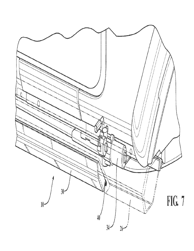
Figure 7 is a side perspective view partially in phantom showing the drive
linkage
mechanism of combination step and obstacle side guard of the present
invention.
DETAILED DESCRIPTION OF THE PREFERRED EMBODIMENTS
The following description of the preferred embodiment(s) is merely exemplary
in
nature and is in no way intended to limit the invention, its application, or
uses.
Referring now to the drawings there is provided a combination step and
obstacle
side guard generally shown at 10 for attachment to a vehicle 12.
The combination step and obstacle side guard 10 has a first hollow housing
portion 14. Housing 14 includes a hollow interior cavity 16 formed by an outer
robust
housing which has a top surface step 18 and bottom obstacle guard surface 20
and a
side surface 22 is provided. The obstacle guard surface 20 Is generally
horizontal to
the ground and includes outer slanted surfaces 24 and 26 between surface 20
and
2
CA 03205517 2023- 7- 18

WO 2022/165010
PCT/US2022/014064
surface 22. An inset cavity 28 is formed between side surfaces 24 and 26. End
cap
surfaces 36 and 38 are provided for enclosing the hollow housing portion 14.
Thus, the
outer housing has six sides on its outer surface with the top being a
horizontal step
surface.
The step and obstacle side guard 10 includes an automated deployable running
board 30 which has a step portion 32 which is stowed in the cavity 28. A drive
linkage
mechanism 34 is provided which is situated within and protected by the hollow
interior
cavity 16 of the first hollow housing portion 14. The drive mechanism 34 is
for driving
the step 30 between a stowed position in the inset cavity and a deployed step
position
as shown in Figure 6 wherein the step portion 32 can be used for stepping into
the
vehicle 12.
In operation the step 30 is stowed and forms an outer slide surface that is
contiguous with the side portions surfaces 24 and 26 such that if an obstacle
is
encountered it will slide along the entire surface and protect the vehicle.
Then when the
vehicle is parked the powered drive mechanism 34 has a four bar linkage that
will drop
the step down to a level step surface for entering or exiting the vehicle.
Such linkages
are known in the art of power automated running boards and are adapted for use

herein. Linkages suitable in the present invention include four bar linkages
shown for
example in co-assigned U.S. Patent No. 10,919,453 by Bradley Watson entitled
"Power
Box Side Step" issued February 16, 2021 assigned to Magna Exteriors, Inc.
which is
incorporated herein by reference. The linkage includes a motor 34 for powering
the
linkage into the deployed or stowed positions. The linkage is configured to
engage the
T-slot 40 of the step portion and either is configured to go through
preconfigured
openings in the housing 14 or the like. It is within the scope of the present
invention to
use a manual linkage which would allow manual opening and closing of the step
into the
deployed and stowed positions as is known in the art.
The present invention provides "a rock guard" type protective lower side area
of a
vehicle but also allowing for an automated running board feature for assisting

passengers in getting in and out of the vehicle. In the present invention the
step is
stowed inside of a robust rock guard enclosure and deployable when necessary.
The
step portion could also be deployed for an extended rock guard or rock slide
feature if
desired.
The description of the invention is merely exemplary in nature and, thus,
variations that do not depart from the essence of the invention are intended
to be within
3
CA 03205517 2023- 7- 18

WO 2022/165010
PCT/US2022/014064
the scope of the invention. Such variations are not to be regarded as a
departure from
the spirit and scope of the invention.
4
CA 03205517 2023- 7- 18

Representative Drawing
A single figure which represents the drawing illustrating the invention.
Administrative Status

For a clearer understanding of the status of the application/patent presented on this page, the site Disclaimer , as well as the definitions for Patent , Administrative Status , Maintenance Fee  and Payment History  should be consulted.

Administrative Status

Title Date
Forecasted Issue Date Unavailable
(86) PCT Filing Date 2022-01-27
(87) PCT Publication Date 2022-08-04
(85) National Entry 2023-07-18
Examination Requested 2024-01-29

Abandonment History

There is no abandonment history.

Maintenance Fee

Last Payment of $100.00 was received on 2023-07-18


 Upcoming maintenance fee amounts

Description Date Amount
Next Payment if small entity fee 2025-01-27 $50.00
Next Payment if standard fee 2025-01-27 $125.00

Note : If the full payment has not been received on or before the date indicated, a further fee may be required which may be one of the following

  • the reinstatement fee;
  • the late payment fee; or
  • additional fee to reverse deemed expiry.

Patent fees are adjusted on the 1st of January every year. The amounts above are the current amounts if received by December 31 of the current year.
Please refer to the CIPO Patent Fees web page to see all current fee amounts.

Payment History

Fee Type Anniversary Year Due Date Amount Paid Paid Date
Registration of a document - section 124 $100.00 2023-07-18
Application Fee $421.02 2023-07-18
Maintenance Fee - Application - New Act 2 2024-01-29 $100.00 2023-07-18
Request for Examination 2026-01-27 $1,110.00 2024-01-29
Owners on Record

Note: Records showing the ownership history in alphabetical order.

Current Owners on Record
MAGNA EXTERIORS INC.
Past Owners on Record
None
Past Owners that do not appear in the "Owners on Record" listing will appear in other documentation within the application.
Documents

To view selected files, please enter reCAPTCHA code :


To view images, click a link in the Document Description column. To download the documents, select one or more checkboxes in the first column and then click the "Download Selected in PDF format (Zip Archive)" or the "Download Selected as Single PDF" button.

List of published and non-published patent-specific documents on the CPD .

If you have any difficulty accessing content, you can call the Client Service Centre at 1-866-997-1936 or send them an e-mail at CIPO Client Service Centre.


Document
Description 
Date
(yyyy-mm-dd) 
Number of pages   Size of Image (KB) 
Request for Examination 2024-01-29 4 124
Assignment 2023-07-18 4 99
National Entry Request 2023-07-18 2 44
Declaration of Entitlement 2023-07-18 1 19
Representative Drawing 2023-07-18 1 52
Patent Cooperation Treaty (PCT) 2023-07-18 2 86
Description 2023-07-18 4 144
Drawings 2023-07-18 4 170
Claims 2023-07-18 1 39
International Search Report 2023-07-18 2 52
Declaration 2023-07-18 1 38
Declaration 2023-07-18 1 41
Priority Request - PCT 2023-07-18 27 1,188
Patent Cooperation Treaty (PCT) 2023-07-18 1 63
Declaration 2023-07-18 2 133
Correspondence 2023-07-18 2 48
National Entry Request 2023-07-18 9 266
Abstract 2023-07-18 1 15
Amendment 2023-08-22 5 138
Cover Page 2023-09-29 1 66
Description 2023-07-19 4 165
Voluntary Amendment 2023-07-18 3 107