Note: Descriptions are shown in the official language in which they were submitted.
- 1 -
COILED ANCHOR FOR SUPPORTING PROSTHETIC HEART VALVE,
PROSTHETIC HEART VALVE, AND DEPLOYMENT DEVICE
BACKGROUND
Field
[0001] The invention generally relates to medical devices and procedures
pertaining
to prosthetic heart valves. More specifically, the invention relates to
replacement of heart
valves that may have malformations and/or dysfunctions. Embodiments of the
invention
relate to a prosthetic heart valve for replacing a mitral valve in the heart,
an anchor to
facilitate and maintain a positioning of the prosthetic heart valve in the
native valve, and
deployment devices and procedures associated with implantation of the
prosthetic heart
valve.
Description of Related Art
[0002] Referring first generally to Figs. 1 and 2, the mitral valve
controls the flow of
blood between the left atrium and the left ventricle of the human heart. After
the left
atrium receives oxygenated blood from the lungs via the pulmonary veins, the
mitral
valve permits the flow of the oxygenated blood from the left atrium into the
left ventricle.
When the left ventricle contracts, the oxygenated blood held in the left
ventricle is
delivered through the aortic valve and the aorta to the rest of the body.
Meanwhile, the
mitral valve closes during ventricular contraction, to prevent the flow of
blood back into
the left atrium.
[0003] When the left ventricle contracts, the blood pressure in the left
ventricle
increases substantially, and urges the mitral valve closed. Due to the large
pressure
differential between the left ventricle and the left atrium during ventricular
contraction, a
possibility of prolapse, or eversion of the leaflets of the mitral valve back
into the atrium,
arises. To prevent this, a series of chordae tendineae connect the mitral
valve to the
papillary muscles along opposing walls of the left ventricle. The chordae
tendineae are
schematically illustrated in both the heart cross-section of Fig. 1 and the
top view of the
Date Recue/Date Received 2023-07-07
- 2 -
mitral valve in Fig. 2. Just before and during ventricular contraction, the
papillary
muscles also contract and maintain tension in the chordae tendineae, to hold
the leaflets
of the mitral valve in the closed position and preventing them from turning
inside-out and
back into the atrium, thereby also preventing backflow of the oxygenated blood
into the
atrium.
[0004] A general shape of the mitral valve and its leaflets as seen from
the left atrium
is illustrated in Fig. 2. Complications of the mitral valve can potentially
cause fatal heart
failure. One form of valvular heart disease is mitral valve leak, also known
as mitral
regurgitation, characterized by the abnormal leaking of blood from the left
ventricle back
into the left atrium through the mitral valve. In these circumstances, it may
be desirable
to repair the mitral valve or to replace the functionality of the mitral valve
with that of a
prosthetic heart valve.
[0005] To this point, mitral valve repair has been more popular than valve
replacement, where prior research and development has been limited. There are
little or
no effective commercially available ways to replace a mitral valve through
catheter
implantation and/or other minimal or less invasive procedures. In contrast,
the field of
transcatheter aortic valve replacement has developed and has gained widespread
success.
This discrepancy stems from replacement of a mitral valve being more difficult
than
aortic valve replacement in many respects, for example, due to the physical
structure of
the valve and more difficult access to the valve.
[0006] The most prominent obstacle for mitral valve replacement is
anchoring or
retaining the valve in position, due to the valve being subject to a large
cyclic load.
Especially during ventricular contraction, the movement of the heart and the
load on the
valve may combine to shift or dislodge a prosthetic valve. Also, the movement
and
rhythmic load can fatigue materials, leading to fractures of the implanted
valve. If the
orientation of a mitral prosthesis is unintentionally shifted, blood flow
between the left
atrium and the left ventricle may be obstructed or otherwise negatively
affected. While
puncturing the tissue in or around the mitral valve annulus to better anchor
an implanted
Date Recue/Date Received 2023-07-07
- 3 -
valve is an option for retaining the placement of the implant, this may
potentially lead to
unintended perforation of the heart and patient injury.
[0007] Referring back to Fig. 2, another issue with mitral valve
replacement is the
size and shape of the native mitral valve. Aortic valves are more circular in
shape than
mitral valves. Furthermore, in many cases, the need for aortic valve
replacement arises
due to, for example, aortic valve stenosis, when the aortic valve narrows due
to reasons
such as calcification and/or hardening of the aortic valve leaflets. As such,
the aortic
valve annulus itself generally forms a more stable anchoring site for a
prosthetic valve
than a mitral valve annulus, which is quite large and non-circular. As such, a
circular
mitral valve implant that is too small may cause leaks around the implanted
valve (i.e.,
paravalvular leak) if a good seal is not established around the valve.
Meanwhile, a
circular valve implant that is too large may stretch out and damage the valve
annulus.
The outer shape of a valve implant can also potentially be manipulated to
better fit the
mitral valve annulus, for example, through fabric cuff additions on an outer
surface of the
implant. However, these additions may restrict valve delivery through a
catheter and/or
minimally invasive procedures, since the additional fabric may be difficult to
compress
and deploy through a catheter.
SUMMARY
[0008] Since many valves have been developed for the aortic position, it
would be
desirable to try to take advantage of these existing valve technologies and to
utilize the
same or similar valves in mitral valve replacements. It would therefore be
useful to create
a mitral anchor or docking station for such preexisting prosthetic valves. An
existing
valve developed for the aortic position, perhaps with some modification, could
then be
implanted in such an anchor or docking station. Some previously developed
valves may
fit well with little or no modification, such as the Edwards Lifesciences
SapienTM valve.
[0009] It would therefore be desirable to provide devices and methods that
can be
utilized in a variety of implantation approaches to facilitate the docking or
anchoring of
such valves. Embodiments of the invention provide a stable docking station for
retaining
Date Recue/Date Received 2023-07-07
- 4 -
a mitral valve replacement prosthesis. Other devices and methods are provided
to
improve the positioning and deployment of such docking stations and/or the
replacement
prosthesis therein, for example, during various non-invasive or minimally
invasive
procedures. The devices and methods may also serve to prevent or greatly
reduce
regurgitation or leaking of blood around the replacement prosthesis, such as
leakage
through the commissures of the native mitral valve outside of the prosthesis.
[0010] Features of the invention are directed to a docking or anchoring
device that
more effectively anchors a replacement valve prosthesis in the mitral valve
annulus.
Other features of the invention are directed to a replacement valve prosthesis
that more
effectively interacts with an anchoring device according to embodiments of the
invention
and with surrounding portions of the native mitral valve and other portions of
the heart.
Still other features of the invention are directed to docking or anchoring
devices and
methods for more effectively deploying different portions of the anchoring
devices above
and below the native mitral valve annulus (i.e., deploying separate portions
of the
anchoring devices into the left atrium and left ventricle, respectively).
Still other features
of the invention are directed to corralling or holding the chordae tendineae
together
during deployment of the docking or anchoring devices, to more easily position
the
docking or anchoring devices around the native valve leaflets and the chordae
tendineae.
[0011] In an embodiment of the invention, a coiled anchor for docking a
mitral valve
prosthesis at a native mitral valve of a heart has a first end, a second end,
and a central
axis extending between the first and second ends, and defines an inner space
coaxial with
the central axis. The coiled anchor includes a coiled core including a bio-
compatible
metal or metal alloy and having a plurality of turns extending around the
central axis in a
first position, and a cover layer around the core, the cover layer including a
bio-
compatible material that is less rigid than the metal or metal alloy of the
coiled core. The
coiled anchor is adjustable from the first position to a second position
wherein at least one
of the plurality of turns is straightened for the coiled anchor to be
delivered through a
catheter to the native mitral valve, and from the second position back to the
first position.
The coiled anchor is implantable at the native mitral valve with at least a
portion on one
Date Recue/Date Received 2023-07-07
- 5 -
side of the native mitral valve in a left atrium of the heart and at least a
portion on an
opposite side of the native mitral valve in a left ventricle of the heart, to
support or hold
the mitral valve prosthesis in the inner space when the coiled anchor is
implanted at the
native mitral valve
[0012] In another embodiment, the coiled anchor can be included in a system
for
implanting at a mitral valve, where the system can further include a mitral
valve
prosthesis including an expandable frame and housing a plurality of leaflets
for
controlling blood flow therethrough, wherein the frame is expandable from a
collapsed
first position wherein the frame has a first outer diameter for delivery of
the mitral valve
prosthesis through a catheter to an expanded second position wherein the frame
has a
second outer diameter greater than the first outer diameter. When the coiled
anchor and
the mitral valve prosthesis are unbiased, a smallest inner diameter of the
inner space
defined by the coil anchor can be smaller than the second outer diameter of
the mitral
valve prosthesis.
[0013] In another embodiment, a coiled anchor for docking a mitral valve
prosthesis
at a native mitral valve of a heart has a first end, a second end, and a
central axis
extending between the first and second ends, and defines an inner space
coaxial with the
central axis. The coiled anchor includes a first coil having a plurality of
turns in a first
circumferential direction and extending from a first end to a second end, a
second coil
having a plurality of turns in a second circumferential direction opposite to
the first
circumferential direction and extending from a first end to a second end, and
a joint
configured to hold the first end of the first coil and the first end of the
second coil
together, such that the first and second coils each extends away from the
joint and from
one another along the central axis. The coiled anchor has a first position
where the
respective turns of the first coil and the second coil each extends around the
central axis.
The coiled anchor is adjustable from the first position to a second position
wherein at
least one of the plurality of turns of the first coil or the second coil is
straightened for the
coiled anchor to be delivered through a catheter to the native mitral valve,
and from the
second position back to the first position. The coiled anchor is implantable
at the native
Date Recue/Date Received 2023-07-07
- 6 -
mitral valve with at least a portion of the first coil on one side of the
native mitral valve in
a left atrium of the heart, and at least a portion of the second coil on an
opposite side of
the native mitral valve in a left ventricle of the heart, to support or hold
the mitral valve
prosthesis in the inner space when the coiled anchor is implanted at the
native mitral
valve.
[0014] In another embodiment, a method for delivering a coiled anchor that
is
configured to dock a mitral valve prosthesis at a native mitral valve of a
heart includes
positioning a catheter for delivery of the coiled anchor at the native mitral
valve,
positioning a loop around chordae tendineae, closing the loop to draw the
chordae
tendineae together, advancing the coiled anchor out of the catheter and around
the
chordae tendineae, and removing the loop and the catheter.
[0015] According to embodiments of the invention, mitral valve replacement
can be
realized through a variety of different implantation approaches. Embodiments
of the
invention thus provide flexibility with different ways and options for
implanting a
replacement mitral valve.
BRIEF DESCRIPTION OF THE DRAWINGS
[0016] Further features and advantages of the invention will become
apparent from
the description of embodiments using the accompanying drawings. In the
drawings:
[0017] Fig. 1 shows a schematic cross-sectional view of a human heart;
[0018] Fig. 2 shows a schematic top view of the mitral valve annulus of a
heart;
[0019] Figs. 3A to 3E show various views of a coil anchor according to an
embodiment of the invention;
[0020] Figs. 4A and 4B are respective images of an uncovered coil and a
covered coil
according to an embodiment of the invention;
[0021] Figs. 5A to 5F show a process of deploying a helical coil anchor via
a
transapical procedure according to an embodiment of the invention;
[0022] Figs. 6A to 6D show a process of deploying a helical coil anchor via
a
transseptal procedure according to another embodiment of the invention;
Date Recue/Date Received 2023-07-07
- 7 -
[0023] Figs. 7A and 7B show side cross-sectional views of a helical coil
anchor
deployed in the mitral position, with and without an implanted valve
prosthesis,
respectively, according to an embodiment of the invention;
[0024] Figs. 8A and 8B respectively show a perspective schematic view of an
exemplary transcatheter valve prosthesis, and a cross-section of a portion of
the valve
prosthesis, according to an embodiment of the invention;
[0025] Figs. 9A and 9B respectively show a valve prosthesis held in a
helical coil
according to an embodiment of the invention, and a flaring that occurs to a
frame of the
valve prosthesis according to an embodiment of the invention;
[0026] Figs. 10A and 10B are respective images illustrating the flaring
effect of a
valve prosthesis according to an embodiment of the invention;
[0027] Figs. 11A and 11B are schematic images showing a cuff or protective
layer
added to a valve prosthesis according to other embodiments of the invention;
[0028] Fig. 12 shows a perspective view of a helical coil anchor according
to another
embodiment of the invention;
[0029] Figs. 13A and 13B respectively show the helical coil anchor of Fig.
12 being
deployed at a mitral position, and the helical coil anchor of Fig. 12 in its
final deployed
position; and
[0030] Fig. 14 shows a modified deployment system according to another
embodiment of the invention.
DETAILED DESCRIPTION
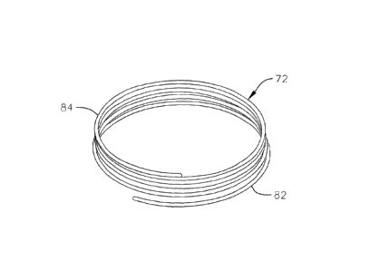
[0031] A helical anchor according to an embodiment of the invention is
constructed
as seen in Figs. 3A to 3E. Fig. 3A shows a perspective view of a helical
anchor 72, Fig.
3B shows a side view of the anchor 72, and Fig. 3C shows a top view of the
anchor 72.
The helical anchor 72 includes a coil with a plurality of turns extending
along a central
axis of the anchor. The anchor 72 has a series of lower turns or coils 82 and
a series of
upper turns or coils 84. The individual turns of the lower coils 82 are spaced
apart from
one another by small gaps. Meanwhile, the individual turns of the upper coils
84 are
Date Recue/Date Received 2023-07-07
- 8 -
wound more closely to one another. In addition, the turns of the lower coils
82 have a
larger radius of curvature than the turns of the upper coils 84, and therefore
form a larger
inner annular space. These features will be discussed in more detail below
with respect to
implantation of the anchor 72 at a native mitral valve. In other embodiments,
the
characteristics and differences between the lower coils 82 and the upper coils
84 of the
anchor 72 can be arranged differently based on, for example, the anatomy of
the patient.
[0032] As can be seen most clearly in Fig. 3C, the anchor 72 twists or
coils around a
central axis of the anchor 72 to provide a generally circular or cylindrical
space therein
that can more easily hold and anchor a circular valve prosthesis than can the
non-circular
shape of the native mitral valve annulus seen in Fig. 2. Therefore, as can be
seen in Fig.
3D, when a helical anchor 72 is positioned about a mitral valve 44, the
helical anchor 72
provides a more solid and structurally stable docking station or site for
docking or
coupling valve prostheses to the native mitral valve annulus. Passage of a
portion of the
anchor 72 at a commissure 80 of the mitral valve 44 (as seen in Fig. 3D, the
process of
which will be discussed in greater detail below) allows for placement of the
anchor 72
both above and below the mitral valve annulus, for more secure anchoring of a
valve
prosthesis therein. In addition, a smallest inner space defined by the coils
of the anchor
72 can be undersized relative to an expanded diameter of a valve prosthesis,
such that a
radial pressure is generated between the anchor 72 and the valve prosthesis
when the
prosthesis is expanded therein.
[0033] In one embodiment, a core 180 of the helical coil 72 is constructed
of or
includes a shape memory material, such as Nitinol. However, in other
embodiments, the
core 180 of the helical coil 72 can be made of or include other bio-compatible
materials,
for example, other alloys, or for example, metals such as titanium or
stainless steel. In
some embodiments, the coil can have enlarged and/or rounded ends, for example,
to
prevent tips at ends of the coil 72 from damaging surrounding tissue during
deployment.
As can best be seen in Figs. 3A, 3B, and 3E, the last of which illustrates a
cross-section of
a portion of the helical coil 72, the core 180 of the coil 72 is covered or
surrounded by a
foam layer 182 and a cloth cover 184. In the embodiment shown, the foam layer
182 is a
Date Recue/Date Received 2023-07-07
- 9 -
Biomerix foam layer, for example, a 2 millimeter thick layer of polyurethane
sheet
material, and the cloth cover 184 is made of or includes a polyester material.
In the
illustrated embodiment, the respective ends of the foam layer 182 and cloth
cover 184
meet circumferentially around the coil core 180 at substantially the same
place.
However, in other embodiments, the foam layer 182 and cloth cover 184 are
wrapped
around the coil core 180 and attached at different circumferential points
around the coil
core 180. The layers 182, 184 can be attached together to the coil core 180,
or can be
attached separately to the coil core 180.
[0034] In greater detail, in some embodiments, the fabric or cloth cover
184 that
covers the helical coil is, for example, a polyethylene terephthalate (PET)
polyester
material. The fabric can have a thickness of 0.008 0.002 inches, and can
have density
characteristics of, for example, 2.12 0.18 oz/yd2, 40 5 wales/inch, and 90
10
courses/inch. The fabric layer can further be cut to have a length or width of
approximately 13 +1/-0.5 inches in order to cover substantially an entire
length of the
helical coil 72.
[0035] In some embodiments, the foam layer 182 can be cut to 19 mm x 5 mm,
and
the cloth cover 184 can be cut to 19 mm x 6 mm. However, other sized cuts of
the
various layers 182, 184 can also be utilized, depending on for example, the
size of the
helical coil, the thickness of the respective layers, and the amount of each
layer intended
for covering the core 180. In some embodiments, the foam layer 182 can be
attached to
the cloth cover 184 using, for example, 22 mm of polytetrafluoroethylene
(PTFE) suture
with a light straight stitch. The foam layer 182 and/or the cloth cover 184
can be folded
around the coil core 180 and cross-stitched to the core 180 using, for
example, 45 mm of
fiber suture. However, the invention should not be limited to these attachment
properties,
and other suture sizes and/or types, or any of various other attachment means
or methods
for effectively attaching the foam layer 182 and/or the cloth cover 184 to the
coil core
180, can also be utilized and implemented. For example, in some embodiments,
the core
can be a modified core with through holes, notches, or other features that can
be laser cut
or otherwise formed along the core. Such features in the core can be used to
interact with
Date Recue/Date Received 2023-07-07
- 10 -
sutures, to increase friction, or to otherwise help hold a cover layer or
layers against the
core and prevent or restrict sliding or other relative movement between the
cover layer
and the core. In some embodiments, the core can also be formed to have a non-
circular
cross-section to increase a contact area between the core and the cover layer.
For
example, a flat wire coil can be used to form the core. Additionally, various
bio-
compatible adhesives or other materials can be applied between the core and
the cover
layer in order to more securely hold a position of the cover layer relative to
the core. In
some embodiments, a hydrogel or other material that expands upon contact with
blood
can be applied between the core and the cover layer as a gap filler to create
a stronger seal
or interference fit between the core and the cover layer.
[0036] Fig. 4A shows a core of one embodiment of a helical anchor prior to
applying
a foam and/or fabric cover thereupon, and Fig. 4B shows a covered helical
anchor, with a
foam layer and a fabric layer, similarly as described with respect to Figs. 3A
to 3E. The
foam and/or fabric layers are bio-compatible, and generally serve to promote
ingrowth of
the surrounding tissue around and into the anchor, to further secure the
anchor about the
mitral valve annulus after the anchor and valve have been implanted. While in
the above
described embodiments, both a foam layer and a fabric layer are applied onto
an alloy
core of the helical anchor, in other embodiments, only a foam layer is applied
onto the
core of the anchor, while in still other embodiments, only a fabric layer is
applied onto the
anchor core.
[0037] According to embodiments of the invention, mitral valve replacement
can be
performed in various different manners. In one procedure using catheters, an
anchoring
or docking station as described above and/or a prosthetic valve to be
positioned in the
anchor (which may initially be compressed or collapsed radially) can be
delivered
through blood vessels to the implant site. This can be accomplished, for
example,
through arteries or veins connected to various chambers of the heart. In one
exemplary
embodiment (as will be seen in Figs. 6A to 6D), a catheter can be delivered
through the
inferior vena cava into the right atrium, and then through a transseptal
puncture to reach
the left atrium above the mitral valve.
Date Recue/Date Received 2023-07-07
- 11 -
[0038] In some cases, mitral valve replacement may not be purely performed
percutaneously through remote arteries and/or veins, and a more open procedure
may be
necessary. In these cases, for example, practitioners can make a small chest
incision
(thoractomy) to gain access to the heart, and then place catheter-based
delivery devices
and/or the implants directly into the heart.
[0039] Referring now to the embodiment in Figs. 5A to 5F, a transapical
procedure
for positioning a coiled or helical anchor in the mitral position of a
patient's heart is
shown. In this example, the anchor is delivered to the mitral position from
the apex of the
heart and through the left ventricle. Fig. 5A shows an introducer 2 inserted
into the left
ventricle 10 of a patient's heart 14 through an incision at the apex 6. To
prevent blood
leakage through the apex 6, a purse string suture can be tightened around the
introducer 2,
or an occluder device can be used, among other options. A guide wire 30 is
advanced
from the introducer 2 through the left ventricle 10, past the papillary
muscles 56, 60 and
the chordae tendineae 48, and between the anterior and posterior leaflets 38,
42 of the
native mitral valve 44, such that a portion of the guide wire 30 is positioned
in the left
atrium 46.
[0040] As shown in Fig. 5B, a delivery catheter 64 is then introduced over
the guide
wire 30 into the left atrium 46. The delivery catheter 64 facilitates the
later introduction
of a coil guide catheter 68, which has a pre-formed curved shaped designed to
assist in
the introduction of a coiled or helical anchor 72. The coil guide catheter 68
is
straightened for introduction through the delivery catheter 64, which can be,
in contrast,
substantially straight and which can be made of a stiffer material than the
coil guide
catheter 68. Therefore, upon exiting the delivery catheter 64, the distal end
of the coil
guide catheter can deflect or revert to its original pre-formed curved shape
to assist with
proper introduction and positioning of the helical anchor 72. The guide wire
30 can be
retracted and removed during the process of deploying and positioning the coil
guide
catheter 68, prior to delivery of the helical anchor 72.
Date Recue/Date Received 2023-07-07
- 12 -
[0041] In other embodiments, the coil guide catheter 68 can be introduced
into the
heart as a relatively straight element, and can then be manipulated to take on
the desired
curved shape.
[0042] As shown in Fig. 5C, in an initial coil delivery position, the
delivery catheter
64 has been removed, and the distal end of the coil guide catheter 68 is
positioned in the
left atrium 46, near one of the mitral valve commissures 80, where the
anterior mitral
valve leaflet 38 meets the posterior mitral leaflet 42 near a perimeter of the
mitral valve
44. In other embodiments, the distal end of the coil guide catheter can
instead be
positioned in the left ventricle 10 near the mitral valve. In Fig. 5C, the
distal tip of the
lower coils 82 of the helical anchor 72 can be seen extending out of the
distal end of the
coil guide catheter 68, and through the mitral valve back into the left
ventricle 10. The tip
of the anchor 72 can have a slight downward turn or bend to facilitate the
initial insertion
and advancement of the tip back at a commissure 80 of the mitral valve 44.
[0043] The helical anchor 72 is then further advanced by being pushed
through the
coil guide catheter 68. Fig. 5D shows the helical anchor 72 being advanced and
twisting
under or around the leaflets 38, 42 of the mitral valve 44. The helical anchor
72 is
directed to go entirely around the leaflets 38, 42 of the mitral valve 44, as
well as the
chordae tendineae 48. The lower coils 82 of the anchor 72 can therefore be
made slightly
larger, to facilitate easier corralling or directing of the anchor 72 around
the leaflets 38,
42, and the chordae 48 during anchor deployment. Additionally, the turns of
the lower
coils 82 can be spaced slightly apart from another, for easier advancement of
the coils 82
through the native valve 44 at the commissure 80. Meanwhile, smaller coils,
such as
those of upper coils 84, can help more securely or tightly hold a valve
prosthesis.
[0044] After the lower coils 82 of the anchor 72 have been placed under the
mitral
valve annulus, as seen in Fig. 5E, the upper coils 84 of anchor 72 are then
deployed from
the coil guide catheter 68. In some embodiments, after the lower coils 82 have
been
advanced under the mitral valve annulus to a desired position, it may not be
desirable to
further push or advance the coil 72, in order to keep or maintain the
orientation and
positioning of the lower coils 82 in the left ventricle 10. Therefore, the
upper coils 84 of
Date Recue/Date Received 2023-07-07
- 13 -
the anchor 72 can be deployed in the left atrium 46 by rotating the coil guide
catheter 68
backwards (as illustrated by the arrows at the bottom of Fig. 5E), in order to
reveal and
deploy more of the coil anchor 72 from within the catheter 68. Other
embodiments
deploy and position the upper coils 82 of the anchor 72 in various different
ways.
[0045] After the helical anchor 72 is fully implanted, the coil guide
catheter 68 is
removed, as can be seen in Fig. 5F. While the deployed anchor in Fig. 5F has
about three
coils positioned above the mitral valve 44 and two coils positioned below the
mitral valve
44, other embodiments can have other different arrangements and coil
positionings based
on the specific application.
[0046] It should also be noted that once a helical anchor 72 is inserted
and positioned
as described above, and prior to implantation of a prosthetic valve therein,
the native
mitral valve 44 can continue to operate substantially normally, and the
patient can remain
stable. Therefore, the procedure can be performed on a beating heart without
the need for
a heart-lung machine. Furthermore, this allows a practitioner more time
flexibility to
implant a valve prosthesis within the anchor 72, without the risk of the
patient being in a
position of hemodynamic compromise if too much time passes between anchor
implantation and valve implantation.
[0047] Figs. 6A to 6D show an alternative procedure for positioning a
helical anchor
in the mitral position of a patient's heart. In this example, an anchor 330 is
delivered to
the mitral position through the atrial septum of the heart. In an example
procedure, a
catheter 332 is introduced into a patient's venous system by percutaneous
puncture or by
a small surgical cut, for example, at the patient's groin. Alternative access
sites can also
be used.
[0048] As shown in Fig. 6A, the catheter 332 is advanced up the inferior
vena cava
212, into the right atrium 210, across the atrial septum 304, and into the
left atrium 46.
Then, in Fig. 6B, a coil guide catheter 340 is deployed from a distal end of
the catheter
332 and extends to a position in the left atrium 46 near a commissure 80 of
the mitral
valve 44, similarly as seen in the embodiment in Figs. 5A-5F. The anchor 330
exits the
Date Recue/Date Received 2023-07-07
- 14 -
tip of the coil guide catheter 340 and is advanced under the mitral valve 44
at the
commissure 80.
[0049] After the lower coils of the anchor 330 have been positioned under
the mitral
valve 44 to a desired orientation, the upper coils of the anchor 330 can then
be deployed
from the coil guide catheter 340, for example, by rotating the coil guide
catheter 340 in
the opposite direction of advancement of the anchor 330, as shown in Fig. 6C.
After the
helical anchor 330 is implanted and placed in a desired position, the coil
guide catheter
340 is removed, as seen in Fig. 6D.
[0050] Fig. 7A shows a side cross-sectional view of a helical anchor 72
that has been
implanted in a mitral position of a patient's heart, and Fig. 7B shows a side
cross-
sectional view of a helical anchor 72 with a valve prosthesis 120 retained
therein.
Orientations, shapes, and size differentials between the different coils of
the anchor 72
other than those illustrated may also be employed for various reasons, for
example, to
cause ends of the anchor 72 to push against the ventricular and/or atrial
walls, in order to
better hold a position of the helical anchor 72.
[0051] In Fig. 7B, a valve prosthesis 120 is retained by the helical anchor
72 in the
mitral position. The valve prosthesis 120 is preferably a modified or
unmodified
transcatheter heart valve, such as, for example, the Edwards Lifesciences
SapienTM valve.
Generally, the valve prosthesis 120 will include an expandable frame structure
126 that
houses a plurality of valve leaflets 122, 124. The expandable frame 126 can be
self-
expanding, or can be, for example, balloon expandable, and can be introduced
through the
same introducer and/or catheters used to introduce the anchor 72, or may be
introduced
through a separate catheter.
[0052] In embodiments of the invention, a collapsed valve prosthesis 120 is
first
positioned in a central passage or inner space defined by the anchor 72, and
is then
expanded to abut against and dock in the anchor 72. In these embodiments, at
least a
portion of the leaflet tissue 38, 42 of the mitral valve 44 is secured or
pinned between the
anchor 72 and the valve prosthesis 120 to lock the anchor 72 and valve
prosthesis 120 in
position and prevent them from shifting or dislodging. The tissue of leaflets
38, 42 also
Date Recue/Date Received 2023-07-07
- 15 -
creates a natural seal to prevent blood flow between the valve prosthesis 120
and the
helical anchor 72. As discussed above, in some embodiments, a smallest inner
diameter
defined by the coils of the anchor 72 is smaller than a diameter of the valve
prosthesis
120 after it has been expanded, such that a radial resistance force is formed
between the
anchor 72 and the valve prosthesis 120, which further secures the parts
together. Pressure
between the anchor 72 and the valve prosthesis 120 can occur either above or
below the
mitral valve 44, or both. Due to the pressure formed between the anchor 72,
the valve
prosthesis 120, and the leaflets 38, 42 therebetween, generally no additional
sutures or
attachments between the valve prosthesis 120 and the anchor 72 or the adjacent
heart
tissue is needed. Due to the different materials used for the anchor 72 and
the prosthesis
120, a circumferential friction force is also generated between parts of the
anchor 72 and
the prosthesis 120 that contact one another, thereby restricting uncoiling and
expansion of
the anchor 72. This interaction will be discussed in greater detail below,
with reference to
Figs. 9A and 9B.
[0053] Figs. 8A-8B show an embodiment of a prosthetic heart valve for use
with a
helical anchor as previously described. Preferably, the valve prosthesis used
with the
helical anchor is, for example, a modified or unmodified transcatheter heart
valve, such as
the Edwards Lifesciences SapienTM valve. Fig. 8A shows a valve having an
expandable
frame structure 220 and a plurality of valve leaflets 222. The frame 220 of
the prosthetic
valve can be self-expanding and can be made of, for example, a shape memory
material
such as Nitinol, or alternatively, can be made of a non-shape memory material.
In some
embodiments, the valve prosthesis is balloon expandable, and is intended for
expansion
within a previously positioned helical anchor. The leaflets 222 can be made
from, for
example, pliable animal tissues such as cow, pig, or horse pericardium or
valve tissue, or
from any other suitable material.
[0054] Attached or integral along a distal or lower end of the frame 220,
the valve
prosthesis further includes an annular ring or cuff 224 which is made of or
generally
includes materials that are less rigid than the materials of the frame 220.
Fig. 8A only
schematically shows a shape of the annular cuff 224 for simplicity, without
additional
Date Recue/Date Received 2023-07-07
- 16 -
attachment features, while Fig. 8B shows a cross-section of a lower portion of
a valve
prosthesis that includes additional attachment features, such as a sleeve 246
that holds the
cuff in place on the frame. In the embodiment shown in Fig. 8B, the annular
cuff 224
substantially surrounds at least the bottom comers 226 of the expandable stent
frame 220
of the valve prosthesis. The annular cuff 224 includes a foam layer 242
surrounding the
bottom comers 226 of the frame 220, a fabric layer 244 covering the foam layer
242, and
an additional cuff retention sleeve or layer 246 for holding the foam layer
242 and the
fabric layer 244 in place. One or more stitches or sutures 248 are made
between the
sleeve layer 246 and one or more portions of the frame 220 to hold the various
portions of
the cuff 224 in place on the frame 220. In the embodiment of Figs. 8A and 8B,
stitching
248 is made at two different axial regions along the frame 220. However, in
other
embodiments, more or less stitching 248 may be employed as needed to retain
the cuff
224 on the frame 220, or any other suitable retention means may be used to
hold the foam
layer 242 and the fabric layer 244 in place on the frame 220, instead of the
sleeve layer
246 and stitching 248. Furthermore, in other embodiments, only the foam layer
242 is
utilized without the fabric layer 244, or only the fabric layer 244 is
utilized without a
foam layer 242, or a ring of any other suitable material can be used to form
the annular
cuff 224. The layer or layers of the annular cuff 224 will generally be made
of one or
more bio-compatible materials, and will generally be made of a material or
materials that
are softer or less rigid than the materials or alloys used in the stent frame
220.
[0055] Fig. 9A
shows an expanded valve prosthesis 120 anchored in a helical anchor
72 according to an embodiment of the invention. Fig. 9B schematically
illustrates a
tendency of the top and bottom ends of the valve prosthesis 120 to
advantageously flare
radially outward (e.g., in the direction of the arrows) upon deployment of the
prosthesis
120 in a helical anchor 72, due to the frictional and resistive forces between
the portions
of the prosthesis 120 and the anchor 72 that contact one another. As discussed
above
with respect to the anchor 72 in Figs. 3A to 3E, a core of the coil anchor
according to
embodiments of the invention is covered with a foam layer and/or a fabric
layer, which
each serve to promote ingrowth after implantation of the anchor in the mitral
position.
Date Recue/Date Received 2023-07-07
- 17 -
Furthermore, the foam or cloth cover of the anchor 72 can serve to prevent or
reduce
trauma to the tissue that surrounds and comes into contact with the anchor 72.
[0056] In addition, the foam layer and/or fabric layer further serve to
create additional
friction upon contact between the anchor 72 and the frame of valve prosthesis
120
anchored therein. In the case of metal-based anchoring or docking stations
that do not
further include a foam and/or fabric layer thereupon, the material or
materials of the
anchoring or docking station may be similar to or the same as the material or
materials
making up the stent frame of the valve prosthesis. In these instances, when
the valve
prosthesis is expanded in the coil anchor and the stent frame of the
prosthesis begins to
contact the coil anchor, there may be minimal or low frictional resistance
between the
stent frame and the coil anchor. Since the unbiased inner diameter of the coil
anchor is
generally smaller than the outer diameter of the expanded valve prosthesis,
and due to the
general wound structure of the helical coil, expansion of the valve prosthesis
against the
helical coil will urge at least the smallest diameter turns of the coil anchor
to stretch
radially outward and to partially unwind. This, in turn, can cause a slight
dislodging or
shifting of the anchor within the mitral valve annulus that may be undesirable
and cause
less effective functionality of the implanted valve prosthesis, or in a worst
case, may lead
to a weaker anchoring of the valve prosthesis in the coil anchor and potential
embolization of the valve prosthesis out of the mitral valve annulus and into
the left
atrium or the left ventricle.
[0057] The foam and/or cloth or fabric covered coil anchor 72 according to
embodiments of the invention serve to add friction between the coil anchor 72
and valve
prosthesis 120 upon contact between the respective parts. Initially, when the
valve
prosthesis 120 is expanded in the coil anchor 72 during implantation of the
replacement
valve, the metal or metal alloy frame 220 of the valve 120 will come into
contact with the
foam 182 or fabric 184 layer of the coil anchor 72, and a circumferential
frictional force
between the contacting surfaces prevents the coil anchor 72 from sliding or
unwinding
under the radially outward forces applied by the expanding frame 220. Such
frictional
forces can be generated, for example, from the difference in materials between
the outer
Date Recue/Date Received 2023-07-07
- 18 -
surface of the cloth or foam covered coil 72 and the metal or alloy frame 220
of the valve
prosthesis 120, from interference between the texturing of the cloth or foam
covered coil
72 against the metal or alloy surface or various edges of the expandable stent
frame 220
of the prosthesis 120, or from an interference or "catching" between the cloth
or foam
covered coil 72 with the edges, transitions or hinges, and/or stitchings on
the outer surface
of the frame 220 of the prosthesis 120. In other embodiments, other means or
reasons for
a circumferential friction or locking between the surfaces of the coil anchor
72 and the
valve prosthesis 120 can be utilized or employed, in order to prevent or
reduce
circumferential migration or expansion of the helical coil 72 upon radially
outward
pressure applied from the expanding valve prosthesis 120.
[0058] According to embodiments of the invention, a helical coil 72 with a
predefined
opening size can more accurately be selected and implanted in a mitral valve
annulus for
holding or supporting a valve prosthesis therein. A surgeon or practitioner
can more
accurately select a coil size and shape together with a desired valve type and
size, and the
interaction between the pieces after implantation will be more predictable and
robust.
The valve prosthesis can be retained more securely in the coil anchor 72,
since there will
be a tighter hold or retention force between the anchor and the prosthesis,
and since there
will be less expansion, shifting, or migration of the anchor within the native
mitral valve
annulus upon expansion of the prosthesis therein.
[0059] Furthermore, the characteristics of the cloth or foam covered coil
anchor 72
according to embodiments of the invention can also assist in easier
implantation and
positioning of the coil anchor 72 itself in the mitral valve annulus, prior to
delivery of the
valve prosthesis. First, due to the additional frictional forces contributing
to helping later
maintain the structural integrity and/or general size and shape of the coil
anchor 72
against an expanded valve prosthesis, the core of the coil can be made to be
thinner
and/or more flexible, which makes the initial delivery of the coil anchor 72
through the
coil guide catheter and into position in the mitral valve annulus easier. In
addition, while
a coil with a smaller diameter inner opening generally holds a valve
prosthesis more
securely, since undesired expansion of the coil anchor 72 by the valve
prosthesis is
Date Recue/Date Received 2023-07-07
- 19 -
prevented or reduced, the coil anchor 72 can also be made slightly larger than
comparable
coil anchors without a foam/cloth cover layer, and advancement of the anchor
72 around
the native mitral valve leaflets and chordae tendineae during deployment of
the anchor 72
can be more easily facilitated.
[0060]
Referring now to Fig. 9B, another advantageous feature of the foam and/or
cloth covered coil anchor is schematically illustrated. In Fig. 9B, only a
portion of a
valve prosthesis 120 that has been expanded in a coil anchor has been
illustrated, with the
coil anchor 72 removed for simplicity, in order to highlight the effect of the
coil anchor
on a valve prosthesis 120 implanted therein. As can be seen in Fig. 9B, the
frame 220 of
the valve prosthesis 120 has ends that have flared radially outwards. The
frames 220 of
the valve implants 120 used in accordance with embodiments of the invention
generally
have a constant expanded width or diameter along the length of the implant. As
described
above, a coil anchor will generally be selected to have an inner opening that
has a
diameter that is smaller than the expanded diameter of the valve prosthesis
120. Since the
friction between the coil anchor 72 and the valve prosthesis 120 prevents or
reduces
uncoiling of the coil anchor, and therefore also prevents widening of the
opening defined
by the coil anchor, an interference fit is formed between the coil anchor and
the portions
of the valve prosthesis 120 that it comes into contact with. Generally, the
valve
prosthesis 120 will be centered or substantially centered on the coil anchor
72, where the
coil anchor 72 directs an inward or resistive force against a central portion
of the valve
prosthesis 120, as illustrated by the arrow pointing towards the center of the
prosthesis in
Fig. 9B. The central portion of the valve prosthesis 120 will therefore be
restricted from
expanding to its fully expanded size. It should be noted that either the
prosthetic valve
size, the size of the coil anchor, or both, can be selected so as to account
for this
somewhat less-than-full expansion, to avoid compromising the hemodynamics
through
the prosthetic valve upon implantation. Meanwhile, the top and bottom ends of
the valve
prosthesis 120, which may not come into contact with the coil anchor 72, will
continue to
try to expand outwards towards their fully expanded size, as further
illustrated by the
Date Recue/Date Received 2023-07-07
- 20 -
arrows near the ends of the prosthesis in Fig. 9B, creating a flaring at the
ends of the
implant.
[0061] Fig. 10A shows a valve prosthesis according to an embodiment of the
invention that has not been implanted in a foam or cloth covered coil anchor,
while Fig.
10B shows the valve prosthesis after it has been expanded within a foam or
cloth covered
coil anchor and with the anchor removed, exhibiting the flaring or widening at
the ends of
the prosthesis as discussed above.
[0062] The flaring exhibited in the valve prosthesis 120 provides a number
of
benefits. The locking dynamic created between the contacting surfaces of the
coil anchor
and the valve prosthesis, coupled with the flared frame geometry of the
prosthesis 120,
combine to increase retention of the anchor within the coil anchor and the
mitral valve
annulus. The flaring and widening of the ends of the valve prosthesis 120 add
a
dimension to the ends of the prosthesis that serve to create an additional
abutment and
obstacle against dislodging of the valve from the coil anchor and potential
embolization
of the valve under elevated pressures within the heart. In preliminary tests,
while
pulsatile pressures up to 70 mmHG and static pressures up to 150 mmHg applied
against
a valve prosthesis anchored in an uncovered metal coil in separate tests did
not dislodge
the prosthetic valve from the coil anchor, the prosthetic valve did dislodge
from the
uncovered anchor at higher static pressures, for example, pressures above 290
mmHg.
Meanwhile, prosthetic valves that were anchored in a covered coil anchor
according to
embodiments of the invention were successfully retained in all of the above
tests.
Therefore, a prosthetic valve can be more effectively retained in a foam
and/or cloth
covered coil anchor. In addition, flaring of the sub-annular portion of the
prosthetic valve
(i.e., the portion of the valve located in the left ventricle) will also more
securely pinch or
hold the native leaflets of the mitral valve against sub-annular portions of
the coil anchor,
further improving retention of the implant.
[0063] Flaring of the ends of the valve prosthesis 120 will increase
contact between
the prosthesis 120 and the surrounding heart tissue, such as the native mitral
valve leaflets
and the chordae tendineae. This could potentially lead to damage of the
surrounding
Date Recue/Date Received 2023-07-07
- 21 -
tissue by sharp edges or corners on the frame 220 of the valve. Referring back
to the
valve prosthesis illustrated in Figs. 8A-9B, the annular cuff 224 is therefore
added to the
sub-annular end of the valve prosthesis 120 to protect the surrounding tissue
of the heart
from the flared ends of the frame 220 which could potentially dig into, cut,
or otherwise
damage the tissue.
[0064] As seen in the previously described embodiments, the annular cuff
224 is
realized as a continuous annular ring covering at least the corners on one end
of the stent
frame 220 of the valve prosthesis. Meanwhile, Figs. 11A and 11B illustrate two
alternative protective cuff arrangements. In Fig. 11A, an alternative cuff
layer 264 traces
along the bottom (i.e., the sub-annular) edge of the stent frame 220 of the
valve prosthesis
120, in order to provide increased protection of the surrounding tissue from
the entire
bottom edge contour of the stent frame 220. In Fig. 11B, another alternative
protective
layer 284 is realized by spherical or ball-shaped protectors attached to the
lowermost
corners of the stent frame 220. The protective layer 284 in Fig. 11B, or other
similar low
profile arrangements, may be desirable in some applications since, for
example, a stent
frame having a lower profile protective layer will be easier to collapse and
deliver
through a catheter or delivery sheath. In addition, while various different
protective
layers are illustrated as being added only to a sub-annular end of the valve
prosthesis 120
in the described embodiments, it will also be understood that similar cuff
layers or other
protective layers can be added to other portions of the valve prosthesis 120
in order to
prevent or reduce trauma to other portions of the surrounding tissue caused by
the
expansion and/or flaring of the stent frame 220.
[0065] The coil anchor 72 described in the previous embodiments is made up
of or
includes one helical coil. Fig. 12 shows a perspective view of a coil anchor
according to
another embodiment of the present invention. In Fig. 12, the coil anchor 400
includes a
first coil 402 that is wound in a first circumferential direction, and a
second coil 404 that
is wound in a second circumferential direction opposite to the first
circumferential
direction. Therefore, the first and second coils 402, 404 can be aligned next
to each other
along a longitudinal axis of the coils, and at least a length of each of the
coils 402, 404
Date Recue/Date Received 2023-07-07
- 22 -
nearest to one another can be aligned or pushed up against one another. In
this
configuration, the adjacent ends of the coils 402, 404 are joined together at
a joint 406,
which in one example is a crimp joint. In another example, the adjacent ends
of the coils
402, 404 are bonded or welded together, or are held together in one of various
other bio-
compatible means, and with or without other bio-compatible materials, that
integrates the
coils 402, 404 into one single anchor or docking station. The coils 402, 404
extend and
wind from the joint 406 in opposite directions, and the first or upper coil
402 terminates
in an upper distal end 408, while the second or lower coil 404 terminates in a
lower distal
end 410. The upper coil anchor 402 (or atrial anchor) is so named because the
upper coil
402 will be positioned in the left atrium, above the mitral valve annulus,
once deployed.
Similarly, the lower coil anchor 404 (or ventricular anchor) is so named
because most of
the lower coil 404 will be advanced or fed through the mitral valve at a
commissure and
will be positioned sub-annularly, below the mitral valve annulus, in the left
ventricle once
deployed. In some embodiments, the coil anchor 400 can have a cover layer or
layers
similar to the cover layers discussed above with respect to the coil anchor
72. In these
embodiments, a core of the coil anchor 400 can be covered, for example, by a
fabric
layer, a foam layer, or another bio-compatible material, or by a combination
of such
layers.
[0066] The coil
anchor 400 can initially be deployed similarly to the coil anchor 72 in
previously described embodiments. As seen in Fig. 13A, a coil guide catheter
68 is
positioned in the left atrium 46, near a mitral valve commissure 80. The coil
anchor 400
is advanced and begins extending out of the distal opening of the coil guide
catheter 68,
and the distal end 410 of the lower coil 404 is directed through the valve at
the
commissure 80 to a sub-annular position in the left ventricle. The coil anchor
400 can be
advanced via push-out force or load, can be pulled out, the sheath can be
withdrawn, or
the anchor 400 can be delivered from the coil guide catheter 68 using one of
various other
known deployment methods. The lower coil 404 is thereafter positioned
similarly to the
coil anchor 72 in previous embodiments. However, during deployment of the
lower coil
404, the upper coil 402 simultaneously advances out of the distal end of the
coil guide
Date Recue/Date Received 2023-07-07
- 23 -
catheter 68, and begins unwinding in an opposite direction, and upwards into
the left
atrium. Due to the opposite winding directions of the upper and lower coils
402, 404, the
central axes of the two coils can remain substantially aligned during and
after deployment
of the anchor 400. Furthermore, due to the opposite winding directions, the
upper and
lower coils 402, 404 will naturally curl or wind in opposite directions when
they exit from
the coil guide catheter 68, and will advance away from one another along a
central axis of
the coil anchor 400 during deployment. In this manner, once the lower coil 404
is
directed through the valve at the commissure 80, since the upper coil 402 will
deploy
upwards rather than following the direction of advancement of the lower coil
404, the
upper coil 402 will naturally move away from the commissure 80, and will not
inadvertently be guided through the valve at the commissure 80.
[0067] The coil anchor 400 is advanced until the joint 406 exits the distal
end of the
coil guide catheter 68. Additional adjustments of the anchor to a final
desired position
may further be made by the practitioner after the coil anchor 400 has exited
the catheter
68, as needed. As can be seen in Fig. 13B, the coil anchor 400 is deployed to
be arranged
similarly to the coil anchor 72 in previous embodiments. In addition, since
the upper and
lower coils 402, 404 are deployed and positioned at the same time, and since
the coil
guide catheter can remain in substantially a same position throughout
deployment of the
coil anchor 400, a latter step of rotating the coil guide catheter 68 in order
to release an
upper portion of the anchor into the left atrium is no longer necessary,
simplifying the
anchor implanting procedure.
[0068] In some embodiments, the upper and lower coils 402, 404 of the coil
anchor
400 can be staggered, where the lower coil 404 is slightly longer than the
upper coil 402.
In this manner, the distal end 410 of the lower coil 404 is configured to exit
the distal end
of the coil guide catheter 68 first, for easier positioning of the distal end
410 through the
valve at the commissure 80. After the distal end 410 of the lower coil 404 is
positioned
through the valve at the commissure 80, the anchor 400 can be fully advanced
and
positioned without adjustment, or with only minor adjustments, to the position
of the coil
guide catheter 68. In other embodiments, the upper and lower coils 402, 404
are
Date Recue/Date Received 2023-07-07
- 24 -
substantially the same length, or the upper coil 402 can be longer than the
lower coil 404.
The relative lengths of the two coils of the coil anchor 400 can be adjusted
based on the
needs of the patient and the preferences of the practitioner, among other
factors.
[0069] As has been seen in previous embodiments, different coil anchors can
be
deployed at the mitral position in different manners. In each embodiment, it
is important
that the leading end, or distal end, of the sub-annular coil (i.e., the
portion of the coil
anchor that advances through the mitral valve into the left ventricle) is
directed
completely around the native leaflets of the mitral valve and around the
chordae
tendineae, in order for the anchor to remain closely positioned to the mitral
valve annulus.
For example, if the distal end of the coil does not go completely around the
chordae
tendineae, and is instead advanced between two chordae, the coil may become
entangled
in the chordae, and/or the sub-annular portion of the coil anchor may be held
under tissue
where the two chordae meet, and thus be deflected farther away from the valve
annulus
than desired. Such a scenario can have negative effects, such as damage to the
coil
anchor and/or the chordae tendineae or the native mitral valve leaflets, or
unstable
anchoring or poor positioning of a valve prosthesis that is held in the coil
anchor.
[0070] Fig. 14 shows a coil anchor deployment system according to an
embodiment
of the invention. In some embodiments, the deployment system has an
arrangement
similar to that of previously described embodiments, with an introducer 2, a
delivery
catheter 64, and a steering catheter or coil guide catheter 68 through which a
helical
anchor 72 is delivered. In the embodiment illustrated in Fig. 14, the
introducer 2 is
positioned through the left ventricle 10, but in other embodiments, the
introducer 2 and/or
other delivery catheters can be positioned through the atrial septum, or any
other access
site that is suitable for delivery of a helical anchor.
[0071] In addition to the catheters associated with the delivery of the
helical anchor, a
separate catheter 18 can be included in the deployment system, and can also be
fed and
advanced through the introducer 2 or other sheath or cannula in the deployment
system.
At a distal end of the catheter 18, a temporary ring or loop 22 is provided,
which is used
to corral, bundle, "lasso," or otherwise draw the chordae tendineae 48
together prior to
Date Recue/Date Received 2023-07-07
- 25 -
deployment of the helical anchor 72. The chordae tendineae 48 then occupy a
smaller
cross-sectional area in the left ventricle 10, which facilitates easier later
deployment of
the distal tip of the helical anchor 72 around the chordae, and placement of
the helical
anchor 72 in the desired or optimal position without any chordal entanglement.
[0072] The
temporary ring or loop 22 can be, for example, a suture or a guide wire, or
any other suitable thread or wire. In some embodiments, the loop 22 is led or
guided
around the chordae tendineae 48 with for example, a grasping tool or one or
more other
tools introduced through the introducer 2 or through another delivery sheath
or cannula.
In other embodiments, the loop 22 is advanced through one or more segmented
guiding
catheters around the chordae tendineae 48. In these embodiments, the loop 22
is closed,
for example, by utilizing a clamping tool or a grasping tool, via tying, or by
one of
various other attachment methods, and then the segments of the guiding
catheter or
catheters are retracted, leaving the loop 22 in its final position around the
chordae. In yet
other embodiments, the loop 22, like the helical anchor 72, is pre-formed to
have a
curvature, such that the loop 22 surrounds the chordae tendineae as it is
deployed. In
some embodiments, after the loop 22 has been closed, an opening defined by the
loop 22
can further be tightened or narrowed, to further bundle or corral the chordae
tendineae 48
closer together. Meanwhile, while Fig. 14 shows the catheter 18 and loop 22
deployed
together with the delivery catheter 64 and the coil guide catheter 68, in
other
embodiments, any combination of catheters can be present when the loop 22 is
deployed
around the chordae tendineae 48. For example, in previously described
embodiments, the
delivery catheter 64 is retracted before the coil anchor 72 is deployed, and a
similar
process can be followed here. Furthermore, in embodiments where the introducer
2 is
positioned in an apical access site, the loop 22 can also loop around the
introducer and/or
one or more of the delivery or coil guide catheters. If, instead, a
transseptal procedure is
performed, a distal end of the loop catheter 18 can instead be advanced
through the mitral
valve from the left atrium into the left ventricle, and the loop 22 can be
deployed around
the chordae tendineae 48, without also bundling or corralling any additional
delivery
catheters or tubes therein.
Date Recue/Date Received 2023-07-07
- 26 -
[0073] After the loop 22 is deployed around the chordae tendineae 48 and
bundles or
otherwise draws the chordae together, and after the helical coil anchor 72 is
deployed
fully around the chordae and is satisfactorily docked in the mitral position,
the loop 22 is
removed. This can be accomplished, for example, by a release of the grasping
tool if one
is utilized, and/or by untying or cutting the suture, thread, or guide wire
used for the loop
22, and then removing the loop together with the other tools and catheters in
the
deployment system from the access site.
[0074] In embodiments where a loop as described above is utilized in a coil
anchor
deployment system, issues arising from a coil anchor being entangled in the
chordae
tendineae during deployment, or from a coil anchor being stuck between two or
more
chordae and being positioned incorrectly, can be mitigated or prevented. In
this manner,
the anchor can be more securely positioned, and a valve prosthesis can also be
more
securely deployed and implanted therein.
[0075] Various other modifications or alternative configurations can be
made to the
helical anchors, valve prostheses, and/or deployment systems according to the
above
described embodiments of the invention. For example, in the illustrated
embodiments,
the coils of the helical anchors are tightly wound near the mitral valve
annulus. In other
embodiments, some of the coils of the anchor may be widened or flared outwards
to make
contact with, for example, the atrial wall of the left atrium. Furthermore,
the number of
coils both above and below the valve annulus can be varied, based on for
example,
properties of the native mitral valve and/or desired positioning of the valve
prosthesis. In
embodiments where upper and lower coils are joined together to form the
helical anchor,
the two coils can be prepared, modified, and/or selected separately based on a
patient's
anatomy or various other factors. In addition, other modifications to the
deployment
system can be employed in order to more efficiently or effectively bundle the
chordae
tendineae during deployment and positioning of the helical anchor. Various
other coil
shapes, lengths, and arrangements and modifications can also be made based on
a wide
range of considerations.
Date Recue/Date Received 2023-07-07
- 27 -
[0076] For purposes of this description, certain aspects, advantages, and
novel
features of the embodiments of this disclosure are described herein. The
disclosed
methods, apparatus, and systems should not be construed as being limiting in
any way.
Instead, the present disclosure is directed toward all novel and nonobvious
features and
aspects of the various disclosed embodiments, alone and in various
combinations and
sub-combinations with one another. The methods, apparatus, and systems are not
limited
to any specific aspect or feature or combination thereof, nor do the disclosed
embodiments require that any one or more specific advantages be present or
problems be
solved.
[0077] Although the operations of some of the disclosed embodiments are
described
in a particular, sequential order for convenient presentation, it should be
understood that
this manner of description encompasses rearrangement, unless a particular
ordering is
required by specific language set forth below. For example, operations
described
sequentially may in some cases be rearranged or performed concurrently.
Moreover, for
the sake of simplicity, the attached figures may not show the various ways in
which the
disclosed methods can be used in conjunction with other methods. Additionally,
the
description sometimes uses terms like "provide" or "achieve" to describe the
disclosed
methods. These terms are high-level abstractions of the actual operations that
are
performed. The actual operations that correspond to these terms may vary
depending on
the particular implementation and are readily discernible by one of ordinary
skill in the
art.
[0078] In view of the many possible embodiments to which the principles of
the
disclosure may be applied, it should be recognized that the illustrated
embodiments are
only preferred examples and should not be taken as limiting the scope of the
disclosure.
Rather, the scope of the disclosure is defined by the following claims.
Date Recue/Date Received 2023-07-07