Note: Descriptions are shown in the official language in which they were submitted.
WO 2022/170307
PCT/US2022/070433
CONSTRAINED LAYER FLOOR AND WALL DAMPING SYSTEMS
USING HIGH-DENSITY REINFORCED CEMENT PANELS
RELATED APPLICATION
The present application claims 35 USC 119 priority from US
Provisional Application Serial No. 63/146,095 filed February 5, 2021, the
contents of
which are incorporated by reference herein.
BACKGROUND
The present invention is generally related to wall systems used in both
interior and exterior construction, and more particularly to such wall systems
designed for improving the acoustic characteristics of structures. For the
purposes of
the present discussion, "wall systems" will be understood to refer to floor,
roof and
ceiling construction as well as walls.
Reducing the amount of noise to which the average person is exposed
is emerging as both an economic and public policy issue. Soundproof or sound-
reduced (collectively referred to as soundproofing below) rooms or buildings
are
desired for a variety of purposes. For example, apartments, hotels and schools
all
often desire rooms with walls, ceilings and floors that significantly reduce
the
transmission of generated sound to avoid annoying people in adjacent rooms.
Soundproofing is particularly important in buildings adjacent to public
transportation, such as highways, airports and railroad lines, as well as in
theaters,
home theaters, music practice rooms, recording studios and others. One measure
of
the severity of the problem is the widespread emergence of city building
ordinances
that specify a minimum Sound Transmission Class ('SIC') rating. Another
measure
is the broad emergence of litigation between homeowners and builders over the
issue of unacceptable noise.
Conventional interior walls are made using wood or metal studs with
drywall panels on both exterior surfaces of the studs, and baffles of
insulation or
plates commonly placed between the studs in an attempt to reduce the
transmission
of sound from one room to the next. Unfortunately, these relatively simple
walls have
achieved limited success in reducing sound transmission. The excessive sound
1
CA 03206222 2023- 7- 24
WO 2022/170307
PCT/US2022/070433
transmission through such walls has led to apartment tenant complaints, and in
some
cases, litigation.
Various construction techniques and products have emerged to
address the problem of noise control, such as: replacement of wooden framing
studs
with light gauge steel studs; alternative framing techniques such as staggered-
stud
and double-stud construction; additional gypsum drywall panel layers; the
addition of
resilient channels to offset and isolate drywall panels from framing studs;
the addition
of mass-loaded vinyl barriers; cellulose-based sound board; and the use of
cellulose
and fiberglass batt insulation in walls not requiring thermal control. All of
these
changes contribute to reducing the noise transmission, but not to such an
extent that
certain disturbing noises (e.g., those with significant low frequency content
or high
sound pressure levels) in a given room are prevented from being transmitted to
a
room designed for privacy or comfort. The noise may come from rooms above or
below the occupied space, or from an outdoor noise source. In fact, several of
the
above-named techniques only offer a three to six decibel improvement in
acoustical
performance over that of standard construction techniques, with no regard to
acoustical isolation. Such a small improvement represents a just noticeable
difference, not a soundproofing solution.
A second concern with the above-named techniques is that each
involves the burden of either additional (sometimes costly) construction
materials or
extra labor expense due to complicated designs and additional assembly steps.
More recently, an alternative building noise control product has been
introduced to the market in the form of a laminated damped drywall panel as
disclosed in U.S. Pat. No. 7,181,891. That panel, known as a constrained
panel, and
including a central layer of acoustic dampening material or adhesive
sandwiched
between conventional wallboard panels, replaces a traditional drywall layer
and
eliminates the need for additional materials such as resilient channels, mass
loaded
vinyl barriers, additional stud framing, and additional layers of drywall. The
resulting
system offers excellent acoustical performance improvements of up to 15
decibels in
some cases. However, such systems are susceptible to water damage, and as such
are unsuitable for exterior construction, or for use in floors or roofs.
Sound rated or floating floor systems are known for acoustically
isolating a room beneath a floor on which impacts may occur, such as
pedestrian
footfalls, sports activities, dropping of toys, or scraping caused by moving
furniture.
Impact noise generation can generally be reduced by using thick carpeting, but
where vinyl, linoleum, tile, hardwood, wood laminates and other types of hard
surfaces including decorated concrete finishes are to be used, a sound rated
floor is
2
CA 03206222 2023- 7- 24
WO 2022/170307
PCT/US2022/070433
desirable and required by codes for acoustical separation of multifamily
units. The
transmission of impact noise to the area below can be reduced by resiliently
supporting or acoustically decoupling and/or dampening the underlayment floor
away
from the floor substructure. The entire floor system contributes to
transmitting the
noise into the area below. If the floor surface receiving the impact is
isolated from
the substructure, then the impact sound transmission will be greatly reduced.
A
dampening material can also reduce transmitted noise. Likewise, if the ceiling
below
is isolated from the substructure, the impact sound will be restricted from
traveling
into the area below.
Sound rated walls and floors are typically evaluated by American
Society for Testing and Materials (ASTM) Standards E90 for Sound Transmission
Class (STC) ratings and E492 with respect to Impact Insulation Class (IIC).
The
greater the IIC rating, the less impact noise and the less airborne sound will
be
transmitted to the area below. The International Building Code (IBC) specifies
that
floor/ceiling installations between units on multi-family buildings must have
an IIC
rating of not less than 50 and an STC rating of not less than 50. Even though
an IIC
rating of 50 meets many building codes, experience has shown that in luxury
condominium applications, floor-ceiling systems having an IIC of less than 55
may
not be acceptable because some impact noise is still audible and considered
annoying at those levels.
Sound mats are known for use in flooring systems. A suitable mat is
disclosed in US Patent No. 10,370,860 which is incorporated by reference.
A second figure of merit for the physical characteristics of construction
panels are their structural capacities; their flexural and shear strength.
Flexural
strength refers to the panel's ability to resist breaking when a force is
applied to the
center of a simply supported panel. Values of flexural strength are given in
pounds
of force (lbf) or Newtons (N). The measurement technique used to establish the
flexural strength of gypsum wallboard or similar construction panels is ASTM C
473-
06a "Standard Test Methods for the Physical Testing of Gypsum Panel Products"
(publication date Nov. 1, 2006). For floors and roofs the standard that can be
used is
ASTM E330 (2014) "Standard Test Method for Structural Performance of Exterior
Windows, Doors, Skylights and Curtain Walls by Uniform Static Air Pressure
Difference" To measure shear capacities in walls ASTM E72 (2015) "Standard
Test
Methods of Conducting Strength Tests of Panels for Building Construction" or
ASTM
E2126 (2019) "Standard Test Methods for Cyclic (reversed) Load Test for Shear
Resistance of Vertical Elements of the Lateral Force Resisting Systems for
Buildings"
can be used. To establish floor and roof diaphragm capacities, ASTM E455
(2019)
3
CA 03206222 2023- 7- 24
WO 2022/170307
PCT/US2022/070433
"Standard Test Method for Static Load Testing of Framed Floor or Roof
Diaphragm
Construction for Buildings" or the AISI TS-7 (2002) "Cantilever Test Method
for Cold-
Formed Steel Diaphragm" are typically used. These standards are available on
the
Internet, and it is understood in the art that such standards change overtime,
but
such changes are acknowledged by those skilled in the art. Conventional
constrained building panels have been found to have limited flexural and shear
strengths.
Thus, it will be seen that there is a need for improved wall systems
that reduce the transmission of noise. There is also a need for improved wall
systems that focus on the reduction of transmission of low frequency sound.
SUMMARY
The above-listed needs are met or exceeded by the present
constrained panel wall system that is designed for either load-bearing or non-
load-
bearing construction applications of walls, ceilings, roofs and floors. An
acoustic
dampening material is sandwiched between dense reinforced fiber cement panels
to
form the present wall system. Due to the enhanced strength of the resulting
system,
either load-bearing floor, roof or walls are potential construction
applications.
Additionally, the present wall system is suitable in non-load-bearing system
and is
usable in any construction where a high-acoustic performance is required,
especially
where low-frequency noise reduction is a priority.
Provided by the present wall system is a high-STC and I IC floor or
wall system including a constrained damping layer sandwiched between
reinforced
cement panels each having a density of 55 pcf (881 kg/m3) or greater. As a
result,
the present system attains high airborne and impact sound ratings. In
addition, the
present system is optionally configured as a load-bearing floor, or a load-
bearing or
non-load-bearing wall system.
By using two dense fiber reinforced cement panels to sandwich a less-
dense material (likely acoustic), the resistive acoustic properties of the
system are
greatly improved when compared to the sum of the material parts alone. The
nature
of the configuration of using the high density panels with the lower density
constrained (sandwiched) material(s) provide an outstanding acoustic
insulation
system, which is also able to support applied floor and wall loads. In a
preferred
4
CA 03206222 2023- 7- 24
WO 2022/170307
PCT/US2022/070433
embodiment, instead of being provided as a prefabricated panel, the present
system
is installed or assembled at the jobsite.
In a preferred embodiment, the present system is assembled onsite,
using the following steps: to an existing frame for a wall, floor or roof, a
first dense,
fiber-reinforced cement panel is attached, the panel having an interior
surface facing
the frame, and an exterior surface; a layer of acoustic dampening material is
applied
to the exterior surface; a second dense, fiber-reinforced cement panel is
attached to
at least one of the dampening material, the first panel, and the frame.
In another embodiment, a building panel is provided, including a first
panel of dense, fiber-reinforced cement, an internal layer of acoustic
dampening
material; and a second panel of dense, fiber-reinforced cement such that the
dampening material is sandwiched between the first and second cement panels.
In still another embodiment, in a manufacturing facility away from the
final building site, a modular structure is constructed using the above-
described
panels of a dampening material sandwiched between dense, fiber-reinforced
cement
panels, then the module is shipped to the site where the final building is
being
erected by stacking and connecting the individual modules. The present
constrained
system is either preassembled as the modular unit or in pieces to be
built/assembled
onto the modules.
More specifically, a method is provided for assembling a wall system
to an existing frame for a wall, floor or roof, including: attaching a first
dense, fiber-
reinforced cement panel to the frame, the panel having an interior surface
facing the
frame, and an exterior surface; applying a layer of acoustic dampening
material to
the exterior surface; and attaching a second dense, fiber-reinforced cement
panel to
at least one of the dampening material, the first panel, and the frame.
In an embodiment, the acoustic dampening material is an adhesive,
and attaching the second dense, fiber-reinforced cement panel includes
inserting at
least one fastener into at least one of the first dense, fiber-reinforced
cement panel
and the frame, then once the acoustic dampening material has set, removing the
at
least one fastener and patching at least one hole created by the fastener. In
an
embodiment, applying the acoustic dampening material is accomplished through
rolling, brushing, spraying or troweling. Optionally, the acoustic dampening
material
is provided in sheet form. In another option, some of the fasteners are
retained and
not removed for retaining the face panel in position.
In an embodiment, the acoustic dampening material is an adhesive
including alkyl abietate, a plant resin and polyvinyl alcohol. In another
embodiment,
the acoustic dampening material is an adhesive applied in a layer of 0.02 inch
to 0.10
5
CA 03206222 2023- 7- 24
WO 2022/170307
PCT/US2022/070433
inch and including a polymer having a glass transition temperature (Tg) of -10
C to
about 30 C. It is contemplated that the adhesive further includes
plasticizer. In still
another embodiment, each of the first and second dense, fiber-reinforced
cement
panels have a density of 55 pcf (881 kg/nn3) or greater.
In another embodiment, a building panel is provided, including, a first
panel of dense, fiber-reinforced cement; an internal layer of acoustic
dampening
material; and a second panel of dense, fiber-reinforced cement such that the
dampening material is sandwiched between the first and second cement panels.
BRIEF DESCRIPTION OF THE DRAW NGS
FIG. 1 is a fragmentary view of a wall created using the present wall
system, with portions removed for clarity;
FIG. 2 is a cross-section taken along the line 2-2 of FIG. 1 and in the
direction generally designated;
FIG. 3 is a graphic representative of test data where sound absorption
at various frequencies of several panel systems was compared;
FIG. 4 is a fragmentary cross-section of a first embodiment of the
present wall system used for STC testing;
FIG. 5 is a fragmentary cross-section of a second embodiment of the
present wall system used for STC testing;
FIG. 6 is a fragmentary cross-section of a third embodiment of the
present wall system used for STC testing; and
FIG. 7 is a fragmentary cross-section of a fourth embodiment of the
present wall system used for STC testing.
DETAILED DESCRIPTION
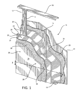
Referring now to FIG. 1, the present sound reducing, constrained
layer damping system is shown as a wall panel or generally indicated by
reference
number 10. For the purposes of the present application, since the same panel
is
usable in floor, wall, ceiling and roof systems, "wall" will be understood to
refer to all
such applications. The present system 10 is intended for use on a frame 12
including regularly spaced vertical studs 14 held in place by headers 16 and
footers
18 using threaded fasteners or the like as are well known in the art. Also as
is well
known in the art, the frame 12 is made of wood or metal components. Further,
the
vertical studs 14 are commonly placed at a 16-inch (40.6 cm) spacing measured
from
their center, but may be spaced as far apart as 24-inches (61.0 cm).
6
CA 03206222 2023- 7- 24
WO 2022/170307
PCT/US2022/070433
It is contemplated that the present system 10 is optionally useful in
modular construction, whereby the present system either arrives pre-assembled
as
panels at a modular manufacturing facility, or as components which are then
mounted onto the individual building modules. These modules are then completed
and transported to an installation site, where they are stacked and connected
to each
other and then form the final modular building. It is also contemplated that
the
modular manufacturing site can be on the construction site or at a remote
assembly
location. Such modular construction is described in commonly-assigned US
Patent
No. 10,066,390 which is incorporated by reference.
Included in the damping system 10 is a first dense, fiber-reinforced,
structural cementitious panel 20 as described in U.S. Patent Nos. 6,986,812;
7,445,738; 7,670,520; 7,789,645; and 8,030,377, which are all incorporated
herein by
reference. It is also contemplated that the term "fiber-reinforced, structural
cementitious panel" also refers to Portland cement-based, Magnesium Oxide
cement-based and polymer cement-based panels. The first panel 20 has an
interior
surface 22 facing the frame 12, and an exterior surface 24. As is known in the
art,
the first panel 20 is secured to the frame 12 using fasteners 26. It is
preferred that
the first panel 20 has a density of at least 55 pounds per cubic foot (pcf)
(881 kg/m3).
It is further preferred that the first panel 20 has a density of at least 80
pcf (1281
kg/m3).
Applied to the exterior surface 24 is an acoustic dampening material
28 contemplated has having a wide range of compositions, but being resilient
and
absorbing sound waves. The dampening material 28 is optionally provided as an
adhesive-like composition or as a sheet of material, and is also referred to
as the
adhesive 28 as a coating or a layer. When the former is utilized, the acoustic
dampening material 28 is applied to the exterior surface 24 using a roller, a
brush, a
trowel, or is sprayed upon the panel 20 using conventional spraying equipment.
When provided as a sheet of material, the dampening material 28 is secured to
the
panel 20 using fasteners 26 or adhesive. In the preferred embodiment, the
dampening material 28 is applied in a thickness of 0.02 inch to 0.10 inch.
A second dense, fiber-reinforced, structural cementitious panel 30,
preferably identical to the first panel 20, is applied to the dampening
material 28 so
that that dampening material is sandwiched between the panels 20, 30. In the
preferred embodiment, the second panel 30 is attached to at least one of the
dampening material 28, the first panel 20, and the frame 12.
By using two dense fiber reinforced cement panels 20, 30 to sandwich
the less-dense acoustic dampening material 28, the resistive acoustic
properties of
7
CA 03206222 2023- 7- 24
WO 2022/170307
PCT/US2022/070433
the system 10 are greatly improved when compared to the sum of the material
parts
alone. The nature of the configuration of using the high density panels 20, 30
with
the lower density constrained (sandwiched) material 28 provides the present
acoustic
insulation system 10, which is also able to support applied floor and wall
loads. In a
preferred embodiment, instead of being provided as a prefabricated panel, the
present system 10 is installed or assembled at the jobsite.
In applications where the acoustic dampening material 28 is a settable
adhesive, attaching the second dense, fiber-reinforced cement panel 30
includes
inserting at least one fastener 32 into at least one of the first dense, fiber-
reinforced
cement panel 20 and the frame 12. Then, once the acoustic dampening material
28
has set, the fasteners 32 are removed and the resulting holes are patched as
is well
known in the art.
In applications where the dampening layer 28 is an adhesive, the
adhesive layer includes a polymer such as a binder. A suitable adhesive 28 is
disclosed in commonly-assigned US Patent Application Serial No. 16,356,303,
filed
March 18, 2019, US 2019/0338516 which is incorporated by reference. The
adhesive
layer preferably has a balance between tackiness and relaxation time. That is,
the
adhesive should be pliable and tacky enough to adhere to both the panels 20
and 30.
Concurrently, sound dampening is improved with a high viscoelastic relaxation
time.
That is, the velocity of sound depends on the elastic modulus of the adhesive
(E (w)).
E (w) can be expressed as E (w) = E '(w) + YE" (w), where E'(w) is the storage
modulus and E"(w) is the loss modulus of the adhesive and each can be
expressed
as EQ. 1 and EQ. 2, where w is frequency (for STC w ranges from 100-5000 Hz)
and
8. is the viscoelastic relaxation time of the adhesive.
E'(w) = _______________________________________________ EQ. 1
1.-F(6,19)2
Gie
E"(w) = E * 1+0)602 EQ. 2
E " (w)
Accordingly, = w9. Therefore, for a high A, the loss modulus is
E (6))
higher as compared to the storage modulus. So, when E"(c.o) is greater than
E'(w) ,
the acoustic attenuation in transmission increases. In addition, the adhesive
preferably should maintain high viscoelastic relaxation time over time and a
range of
temperatures.
In a preferred embodiment, the polymer of the adhesive layer 28 is
synthetic latex (i.e., an aqueous dispersion of polymer particles prepared by
emulsion
polymerization of one or more monomers). The latex is a film-forming polymer.
The
8
CA 03206222 2023- 7- 24
WO 2022/170307
PCT/US2022/070433
adhesive coating used to form the adhesive layer comprises an aqueous emulsion
or
dispersion comprising water, surfactant, and latex polymer selected from the
group
consisting of acrylics, styrene acrylics, acrylic esters, vinyl acrylics,
vinyl chloride
acrylic, styrene acetate acrylics, butyl acrylics, ethyl acrylics, ethylene
polyvinyl
acetate, polyvinyl acetate, styrene butadiene, and combinations thereof. If
desired,
the adhesive coating can have an absence of one or more of the foregoing
polymers.
Typical acrylics are polymers made from polymers of acrylic acid or acrylates,
for
example, polyacrylate, poly butyl acrylate, poly ethyl acrylate.
Preferably the latex polymer is selected from styrene-butadiene latex,
styrene acrylic polymer, or acrylic ester polymer. Preferably, the latex
polymer glass
transition temperature is in the range from about -10 C to about 30 C, more
preferably from about 5 00 to about 30 C, more preferably from about -10 C
to
about 20 00, and more preferably from about 10 00 to about 20 C.
Typically, the adhesive compositions 28 have at least 10 wt. %, more
typically at least 20 wt. % latex polymer. For example, typically 15 to 70 wt.
%, 45 to
70 wt. % or 45 to 60 wt. % latex polymer.
The adhesive compositions 28 may also include a plasticizer.
Typically, the adhesive compositions 28 have 0 to 50 wt. % more typically 5 to
50 wt.
%, furthermore typically 10 to 30 wt. % plasticizer. However, the adhesive
compositions of the invention may have an absence of plasticizer.
Typical plasticizers may be any of abietates, phthalates, terephthalates,
benzoates, and epoxidized oils such as epoxidized soybean oil (ESO),
preferably the
abietates.
The plasticizer improves both tack and sound attenuation. The term
"tack" refers to the ability of a material to stick to the surface on
momentary contact
and then to resist separation.
Typical abietates are alkyl abietate, e.g., methyl abietate or ethyl abietate,
or aralkyl abietate, for example benzyl abietate. The abietate is believed to
work like
a plasticizer and can be used to adjust the softness and tackiness of the
adhesive.
The alkyl portion of the alkyl abietate can be a saturated linear or
branched Cl to 016, preferably Ci to 08, alkyl group. The aralkyl group is
typically
benzyl.
Typical abietate plasticizers for use in the present invention are shown in
Formula (I).
9
CA 03206222 2023- 7- 24
WO 2022/170307
PCT/US2022/070433
0
wherein R is a saturated linear or branched C1 to C18, typically Ci to Ci8 or
C1 to C8 or
Ci to C4, alkyl group or an aralkyl group, preferably benzyl.
A representative of the alkyl abietate family, methyl abietate, is shown in
Formula (II).
0
0
Another representative of the alkyl abietate family, hexadecyl ester of
abietic acid (i.e., cetyl abietate), is shown in Formula (Ill).
0 ,===
="'
wherein R is a linear alkyl group having the formula C16H33.
The adhesive compositions 28 also optionally include a resin. Typical
resins may be any one or more synthetic resins. Typical resins may include any
one
or more plant resins. For example, typically one or more plant resins such as
wood
or gum rosin, ester gum, hydrogenated rosin, clarnmar gum, manila gum,
coumarone-
indene resin, copal, kauri gum, ethyl cellulose, mastic, and/or sandarac.
CA 03206222 2023- 7- 24
WO 2022/170307
PCT/US2022/070433
Typically, the adhesive compositions 28 have 0 to 25 wt. %, more
typically 5 to 20 wt. % resin. However, the adhesive 28 is contemplated has
having
an absence of resin.
The adhesive compositions 28 also optionally include a polyvinyl
alcohol.
Typically, the adhesive compositions 28 have 0 to 20 wt. %, more
typically 5 to 15 wt. % polyvinyl alcohol. However, the adhesive compositions
28
optionally have an absence of polyvinyl alcohol.
A preferred adhesive composition 28 for achieving a balance of
properties comprises the above-described polymer and a plasticizer, preferably
an
alkyl or aralkyl abietate plasticizer.
A more preferred adhesive composition 28 includes a mixture of
acrylic polymer, resin, polyvinyl alcohol and alkyl abietate. The acrylic
component,
resin, and polyvinyl alcohol can provide tack. Further, the hydrogel nature of
polyvinyl alcohol also allows it to retain some water in it, which helps with
workability
and reduction sound transmission of the adhesive.
To improve the workability, different inorganic components (e.g.,
calcium carbonate, anhydrous gypsum, etc.) can be also included.
If desired particles of sound compliant material and particles of sound-
stiff material can also be included in the polymer adhesive layer 28. Such a
polymer
adhesive layer 28 includes the polymer adhesive as binder and a combination of
first
particles (the particles of sound compliant material) which are mostly
compliant with
respect to sound transmission and second particles (the particles of sound-
stiff
material) which are mostly stiff with respect to sound transmission.
It will be appreciated that the term "compliant material" is used
interchangeably with the term "sound-compliant material" and it is understood
broadly in this disclosure to mean a material which is at least partially
flexible and
able to transfer, dissipate and/or absorb sound waves through its body at
least
partially. It will be further appreciated that the term "stiff material" is
used
interchangeably with the term "sound-stiff material" and is understood broadly
in this
disclosure to mean any material which is likely to reflect most of energy from
sound
waves rather than transfer, dissipate and/or absorb the sound waves.
If desired, the sound-compliant particles are larger in size than sound-stiff
particles such that each sound-compliant particle is surrounded with several
sound-
stiff particles. In other embodiments, sound-compliant particles and sound-
stiff
particles are of about same size. If desired, the sound-compliant particles
and
sound-stiff particles are used in the equal molar ratios. However, if desired
the
11
CA 03206222 2023- 7- 24
WO 2022/170307
PCT/US2022/070433
sound-compliant particles are the main component and sound-stiff particles are
used
in only much smaller amounts. In other embodiments, this ratio is reversed.
For
example, the molar ratio of sound-compliant particles to sound-stiff particles
in the
compliant coating may be from 1:1 to 1:1,000 or the molar ratio of sound-
compliant
particles to sound-stiff particles is 1,000:1 to 1:1.
If desired, the polymer adhesive layer 28 includes sound-compliant
rubber particles, such as for example tire scrap particles, with sound-stiff
nanometric
silica particles. It will be further appreciated that any sound-compliant
particles are
optionally used, including, but not limited to, nitrile rubber, butyl rubber,
ethylene
propylene diene monomer (EPDM), natural rubber compounds, cotton fibers,
organic
fibers, inorganic fibers, polypropylene fibers, air-filled glass beads,
polystyrene beads
or polystyrene foam.
It will be also appreciated that any sound-stiff particles are usable in
the compliant coating 28. Such sound-stiff particles may include, but are not
limited
to, silica particles, clay particles, calcium carbonate, perlite, gas-filled
microspheres,
hollow microspheres, cenospheres and inorganic glues. If desired, a
combination of
several sound-compliant materials can be mixed together with at least one
sound-stiff
material. If desired, a combination of several sound-stiff materials can be
mixed
together with at least one sound-compliant material. If desired, a combination
of
several sound-stiff materials can be mixed together with several sound-
compliant
materials.
However, without being limited by theory, sound has a higher
transmission velocity through solid particulates. Therefore, to create the
sharp
discontinuity in velocity of sound at the different layers, the adhesive layer
28
preferably does not include solid particulates. Generally, the polymer
adhesive layer
28 has an absence of mineral filler. Generally, the polymer adhesive layer 28
has an
absence of gypsum. Generally, the polymer adhesive coating 28 applied has an
absence of gypsum. Generally, the polymer adhesive coating 28 applied has an
absence of calcium carbonate. Generally, the polymer adhesive coating 28
applied
has an absence of magnesium carbonate. Generally, the polymer adhesive coating
28 applied has an absence of pigment. Generally, the polymer adhesive coating
28
applied has an absence of polyurea. Generally, the polymer adhesive coating 28
applied has an absence of inorganic particles. Generally, the polymer adhesive
coating 28 applied has an absence of organic particles.
Generally, the polymer adhesive coating 28 applied has an absence of
hydroxyethyl cellulose.
12
CA 03206222 2023- 7- 24
WO 2022/170307
PCT/US2022/070433
Generally, the adhesive layer 28 is applied in an amount equal to that
to form a polymer coating having a thickness of about 0.02 inches (0.051 cm)
to
about 0.06 inches (0.152 cm), a thickness of about 0.02 inches (0.051 cm) to
about
0.05 inches (0.127 cm).
In one embodiment, the adhesive layer 28 is applied by at least one
method selected from the group consisting of spray coating, dip coating, rill
application, free jet application, blade metering, rod metering, metered film
press
coating, air knife coating, curtain coating, flexography printing, and roll
coating.
Methods for preparing synthetic latexes are well known in the art and
any of these procedures can be used. Latexes typically have 1-55 wt. % binder
(polymer) and water. Latex is an emulsion with emulsified polymer particles
that can
vary from 30 nm to 1500 nm. Therefore, the adhesive coating can comprise the
emulsified polymer particles with an absence of other particles including
solid
particles, for example filler particles. Once the adhesive coating is applied
and is the
adhesive layer in the final inventive product, the latex forms a film (e.g., a
continuous
film) and is not in particulate form. Therefore, the adhesive layer can have
an
absence of particulates.
Referring now to FIG. 3, test results of a small scale STC test are
shown. The small scale test method was a table-top arrangement: A material
sample (gypsum wallboard or other panel), with approximate dimensions of 4"
(10.2
cm) wide by 48" (121.9 cm) long, is held in place on each of long ends of the
sample
by silicone rubber padded clamps to mitigate undesirable vibrations. An
electrodynamic shaker is placed upon vibration isolation pads and securely
fastened
to the table. An impedance head is attached to the shaker to measure the input
force
(frequency and amplitude), which will be used to normalize the frequency
response
function. The shaker is attached to the material sample at one end and is
excited
with a random noise signal ranging from 100 to 4000 Hz. Micro-accelerometers
are
attached equidistant points along the length of the material sample and are
used to
measure the frequency response function at the equidistant points along the
material
sample. The output frequency response function (frequency and amplitude)
measured by the accelerometers is compared to the input frequency response
function (frequency and amplitude) measured by the impedance head at the
shaker. The difference between these input and output frequency responses is
then
correlated to acoustic transmission loss of the material sample.
Referring again to FIG. 3, it is seen that the preferred constriction of
structural panels 20, 30 sandwiching a layer of adhesive 28, shown as
Structural
Panels with Glue, provided superior sound reduction results at all frequencies
13
CA 03206222 2023- 7- 24
WO 2022/170307
PCT/US2022/070433
compared to a single structural panel alone, a pair of structural panes or
conventional
gypsum wallboard (NatGyp Board).
Referring now to FIGs. 4-7, additional SIC tests were performed on
various experimental embodiments of the sound reducing constrained layer
damping
system 10. Results of the additional STC tests are shown in Tables 1 and 2
below.
The SIC test results presented below were obtained via laboratory testing
conducted
according to the ASTM E90 Standard Test Method of Airborne Sound Transmission
Loss of Building Partitions and Elements. Further, the SIC values were
calculated
from measured sound transmission losses according to ASTM E413 Classification
for
Rating Sound Insulation. Elements which are common to each of the experimental
embodiments of the system 10 are labeled with the same reference numerals. It
is
understood that variations of the described experimental embodiments are
within the
scope of the present disclosure.
Referring to FIG. 4, a first experimental embodiment of the system 10
is generally labeled 100 and includes a Type X gypsum panel 102, a pair of
steel
studs 104, fibrous insulation 106, and a pair of high-density reinforced
cement panels
108. The Type X gypsum panel 102 and the pair of high-density reinforced
cement
panels 108 are located on opposite sides of the steel studs 104. Additionally,
the
Type X gypsum panel 102 is fastened to the steel studs 104 by Type S screws
(not
shown), and the steel studs 104 are 20-gauge steel studs. Moreover, the steel
studs
104 are 3.675-inch steel studs placed at 24-inch spacing measured from their
center.
Additionally, the steel studs 104 have a thickness of 0.033 inches (0.083 cm).
Further, the high-density reinforced cement panels 108 are fastened to the
steel
studs 104 by self-drilling wing screws (not shown). The Type X gypsum panel
102 is
0.675 inches (1.71 cm) thick, and the high-density reinforced cement panels
108 are
each 0.5 inches (1.27 cm) thick.
As shown in FIG. 5, a second experimental embodiment of the system
10 is generally labeled 200 and includes each of the features of the first
experimental
embodiment 100. However, the second experimental embodiment 200 also includes
the acoustic dampening material 28 located between the high-density reinforced
cement panels 108. The acoustic dampening material 28 is applied as a coating
between approximately 0.01 inches (0.025 cm) and 0.015 inches (0.038 cm)
thick.
Table 1 below shows the results of the SIC tests performed on the
first and second experimental embodiments 100, 200.
14
CA 03206222 2023- 7- 24
WO 2022/170307
PCT/US2022/070433
Table 1
First Experimental Embodiment 100 STC 50
Second Experimental Embodiment 200 STC 53
Importantly, the mass of the acoustic dampening material 28 is
insignificant compared to the overall mass of second experimental embodiment
200.
Accordingly, the increase of 3 STC between the first and second experimental
embodiments 100, 200 is attributable to the dampening effect of acoustic
dampening
material 28. A difference of 3 STC points roughly correlates to a difference
in
transmitted sound of 3 decibels (dB), which is perceived as a noticeable
difference to
the average human ear. Therefore, the presence of the acoustic dampening
material
28 provided a noticeable performance improvement.
Referring to FIG. 6 a third experimental embodiment of the system 10
is generally labeled 300 and includes the two steel studs 104 and the
insulation 106.
Additionally, two adjacent Type X gypsum panels 102 are located on each side
of the
steel studs 104 and are fastened to the steel studs 104 by Type S screws (not
shown). The third experimental embodiment 300 does not include the acoustic
dampening material 28.
Referring to FIG. 7, a fourth experimental embodiment of the system
10 is generally labeled 400 and includes the two steel studs 104 and the
insulation
106. Additionally, two adjacent high-density reinforced cement panels 108 are
located on each side of the steel studs 104 and are fastened to steel studs
104 with
self-drilling wing screws (not shown). Moreover, the acoustic dampening
material 28
is applied between the adjacent high density reinforced panels 108.
Table 2 below shows the results of the STC tests performed on the
third and fourth experimental embodiments 300, 400.
Table 2
Third Experimental Embodiment 300 STC 48
Fourth Experimental Embodiment 400 STC 60
Importantly, the total panel weight for the third experimental
embodiment 300 is approximately 9 lb/ft2 (0.379 kg/m2), whereas the total
panel
weight for the fourth experimental embodiment 400 is approximately 13
lb/ft2(0.548
kg/m2). As understood by a person of ordinary skill in the art, the mass law
of sound
transmission loss states that sound transmission loss increases at a rate of 6
dB with
CA 03206222 2023- 7- 24
WO 2022/170307
PCT/US2022/070433
each doubling of mass, which roughly equates to a theoretical increase of 6
STC
points with each doubling of mass.
Based on the difference in total panel weight between the third and
fourth experimental embodiments 300, 400, the mass law suggests that the
fourth
experimental embodiment 400 should yield sound transmission loss performance
between 2 ¨ 3 dB (2 ¨ 3 STC points) higher than the third experimental
embodiment
300. Instead, a performance improvement of 12 STC points is realized with the
fourth experimental embodiment 400 compared to the third experimental
embodiment 300. Therefore, the acoustic dampening material 28 applied between
high-density reinforced cement panels 108 is the primary reason for the 12 STC
point
performance improvement.
While a particular embodiment of the present constrained layer floor
and wall damping systems using high-density reinforced cement panels has been
described herein, it will be appreciated by those skilled in the art that
changes and
modifications may be made thereto without departing from the invention in its
broader
aspects and as set forth in the following claims.
16
CA 03206222 2023- 7- 24