Note: Descriptions are shown in the official language in which they were submitted.
WO 2022/155711
PCT/AU2022/050032
1
BUILDING MODULES AND TECHNIQUES TO MAKE THEM
PRIORITY DETAILS
[ 0 0 0 1] The present application claims priority from 202141003403, filed in
India on
25 January 2021, the entirety of which is incorporated herein by reference.
TECHNICAL FIELD
[0002] The present invention relates generally to the field of building
construction. More
specifically, the invention relates to building materials and methods of
building construction.
BACKGROUND
[0003] Generally, building is costly, laborious and time-consuming. Hence, the
need for
greater efficiency, less labour-intensive processes and cheaper building
materials and
methods.
[0004] Traditionally, sand-bags have been used to build some structures, but
these
structures were usually only temporary. There are drawbacks of using sandbags.
Firstly,
they have low tensile strength, and because of this, any structures made from
sandbags
tend to be for unimportant structures. Secondly, sand-bags tend to
deteriorate, which makes
them impractical for permanent structures.
[0005] An advanced way for building the structures is to use 'conventional
bags combined
with barbed wire' as disclosed in U.S. Patent No. 5,934,027. The method
usually involves
filling standard-sized bags from one end, laying them horizontally and
compacting them. The
fill is usually not only sand but a composite material that has greater
cohesiveness. This
material is sometimes stabilised with cement or lime. Sometimes the bags are
open-ended
fabric tubes, with folds on each end to contain the earth. This methodology
discloses the
use of long bags too. Sometimes strands of barbed wire are used between
courses to
CA 03206292 2023- 7- 25
WO 2022/155711
PCT/AU2022/050032
2
provide tensile strength and shear capabilities. Prior to this method and
since, sandbags
and similar technologies have been used in the construction of darns, dykes,
fortifications,
retaining walls, drainage systems and other temporary constructions. This
advancement
enabled the technology for domestic-scale architecture, especially to create
walls, vaults,
cupolas, arches and domes. This methodology has a limitation that the bags
used in it
cannot be very long and continuous. Even if the bags are somehow longer, it is
a challenge
to fill them evenly, and with additional length, the process of filling and
setting the courses
becomes more labour intensive. Such limitations make the process of making the
structures
difficult, error-prone and time-consuming.
[0006] Hence, there is a need to provide a technique which can help to make
construction
faster, easier and cheaper.
SUMMARY OF THE INVENTION
[0007] The present invention relates to a building module, to be used for the
construction of
structures, which includes a fabric sheet, a filling material and a holding
means. The fabric
sheet wraps around the filling material to form folds over the filling
material, with the edges
of the wrap's folds to be held in place by the holding means. The fact that
these wraps can
be continuously filled from above to make building modules that are otherwise
functionally
like the state of the art, means that the process of construction can be
continuous and easy,
rather than as a series of difficult, labour intensive steps. This enables
structures to be
constructed quickly and in a cost-effective way.
[0009] According to one embodiment of the building module, wherein the fabric
sheet is
made of a synthetic material or a natural fibre material, or combination
thereof. Such fabric
sheets provide longevity to the building module and reinforcing to add tensile
strength and
cohesiveness to the fill material, and therefore to provide better support to
the structures
where they are used.
[0010] According to another embodiment of the building module, wherein the
filling material
is a composite of at least one of sand, silt, clay, gravel, other types of
earth material, organic
CA 03206292 2023- 7- 25
WO 2022/155711
PCT/AU2022/050032
3
material, recycled waste, bonding agents or combination thereof. Various
combinations of
the filling materials shall serve different purposes. Clay and other bonding
agents are useful
as they add extra cohesiveness because they glue particulates together. The
other
aggregates (silt, sand, gravel) stop clay from being too reactive (swelling
with humid
conditions and shrinking when dry). Sand and gravel also add compressive
strength.
Cement and lime add permanent, waterproof cohesiveness. In general, organic
materials
will not be used in construction except where they act as a bonding agent or
fibre to improve
tensile strength. On the other hand, organic materials might be used for
different purposes
again, such to make planters and retaining walls, where the fill is to enable
plants to grow.
[0011] According to yet another embodiment of the building module, the
building module
includes a bonding agent. The bonding agent includes at least one of lime,
clay, cement,
proteins, gypsum, fibre or glue, or combination thereof.
[0012] According to one embodiment of the building module, wherein the filling
material
inside the wrap is compressed or compacted. This helps in making the building
module
stable which further provides stability to the structures in which they are
used.
[0013] According to another embodiment of the building module, wherein the
fabric sheet
has edges which are folded up and over the filling material, one edge of the
fabric over the
other. This way of making the building module shall be helpful to make them as
long
(continuous), fillable from above, and easier to produce using continuous
mechanical
processes.
[0014] According to yet another embodiment of the building module, wherein the
holding
means are at least one of a stitching means or an adhesive, or a pinning
means, or from the
mass exerted by a subsequent building module over this module, or combination
thereof.
The stitching means and the pinning means are affixed to the wrap and
penetrate both
layers. Adhesive, where used, is provided between the two layers of the wrap.
Such holding
means allows versatility for the builders and provides an easy way to complete
the building
modules faster.
CA 03206292 2023- 7- 25
WO 2022/155711
PCT/AU2022/050032
4
[0015] According to one embodiment of the building module, where the building
module
needs to be extended beyond the cut length of the fabric sheet, additional
fabric sheets can
be added, such that at one end of the first fabric sheet, a start of a second
fabric sheet is
wrapped as one. Both the first fabric sheet and the second fabric sheet wrap
around the
filling material and the edges of at least one of the wraps are held by the
holding means.
This embodiment is helpful to extend building modules so that modules are not
limited by
lengths of the fabric sheet.
[0016] According to yet another embodiment of the building module, the fabric
sheet is
wrapped around the filling material in a spiral configuration such that folds
are formed around
the filling material about each turn of the spiral, and the edges of the
wrap's folds overlap
along substantially each consecutive turn of the spiral. The folds run oblique
to an axis of
the building module, the overlapping edges run oblique to the axis of the
building module,
and the holding means run oblique to the axis of the fabric sheet and to the
overlapping
edges.
[0017] Another aspect of the present invention relates to a method for making
a building
module, which includes various steps. First, spreading a fabric sheet onto a
base or a
preceding course made of the building module. Second, placing a composite
filling material
into a form, which may be a container, wherein the container has an opening at
the bottom
of the container. Third, compressing the filling material from the top through
a compressing
means. Fourth, wrapping the fabric sheet up and over to the compressed
material by folding
one side of the fabric sheet along a length of the sheet and over another, and
at the very
ends, once the courses are complete, folding those over also. Fifth, providing
a holding
means to hold the wrapping of the fabric sheet firmly. This method can be
implemented
manually, in a semi-mechanized fashion, or in a completely mechanized fashion
using
standard formwork or a custom-made machine.
[0018] Another aspect of the present invention relates to a device for making
a building
module according. The device includes a filling means and a folding means. The
filling
means includes a top part having a top opening and a bottom part having a
bottom opening,
such that through the top opening, a composite filling material is filled
through the bottom
opening onto a fabric sheet. The folding means fold the edges of the fabric
sheet, one over
CA 03206292 2023- 7- 25
WO 2022/155711
PCT/AU2022/050032
the other once the filling material is in place on the fabric sheet. Such a
device helps to
mechanize the process for making the building module, which helps to build the
modules
faster and more consistently.
[0019] According to one embodiment of the device, wherein the folding means is
having two
walls, such that to allow the filling means to slide between the walls folding
means, leaving
a gap to allow sides of the fabric sheet to pass through the gap. This
embodiment further
provides for an efficient mechanism to carry out the filling of the fill
material, as well as folding
of the sheet almost simultaneously, further automating the process and
decreasing the time
to make the building modules. This makes the handling of the long lengths of
fabric sheeting
easier and therefore the making the building module less fiddly.
[0020] According to another embodiment of the device, wherein the walls of the
folding
means are slidable over a base or a previous course of the building module.
This shall help
in the placement of the device easily on the previous course of the building
module.
[0021] According to yet another embodiment of the device, the device includes
one or more
pairs of guiding means coupled to the walls of the folding means, which allows
the device to
be easily placed directly over a base or a previous course of the building
module. Guiding
means shall further simplify the placement of the device directly over the
previous course of
the building modules
[0022] According to one embodiment of the device, wherein the folding means
includes two
flanges, such that side edges of the fabric sheet when placed into the device
shall be
functionally coupled to each of the flanges. A front part of the flanges is
outspread to allow
spreading of the fabric sheet. In the middle section, the flanges are bent
upwards (but still
coupled to the fabric sheet) to create a form to receive and contain the
filling material and to
allow for compaction. The rear section of the flanges, still functionally
coupled to the edges
of the fabric sheet, fold again to become substantially parallel to each
other, to complete the
folds of the fabric sheet over the filling material. Such flanges enhance the
automation of
folding of the fabric sheet edges so the process can take place without human
intervention.
It makes the process of making building modules more mechanisable.
CA 03206292 2023- 7- 25
WO 2022/155711
PCT/AU2022/050032
6
[0023] According to another embodiment of the device, the device includes a
compressing
means which compresses the filling material once it is placed onto the fabric
sheet through
the filling means. The compressing means mechanize the steps of compressing
the filling
material, which further reduces the need for human intervention, therefore
making the
process of building the modules still more continuous, automatic, and fast.
[0024] According to yet another embodiment of the device, wherein the
compressing means
includes one or more compressing rollers to compress the filling material from
above once
it is placed onto the fabric sheet through the filling means. Rollers are used
to compress the
filling material by applying pressure to the rollers and rolling over it; a
simple mechanism to
compress the filling composite.
[0025] In other embodiments of the device, the compressing means includes one
or more
vibrating compactors to compresses the filling material once it is placed onto
the fabric sheet
through the filling means. Vibrating compactors are lighter, and are powered,
but are a better
way to compress the filling material.
[0026] According to yet another embodiment of the device, the device includes
a holding
means which is used to seal the wrap once it is formed by the folding ends of
the fabric
sheet over each other. The sealing is carried out using an adhesive, a pinning
means or
stitching means, or combination thereof. The stitching means and the pinning
means
penetrate both folds of the wrap. The adhesive is provided between the folds
of the wrap.
This embodiment provides for various options for holding means which can be
used as per
the requirements of a particular user or usage.
[0027] According to one embodiment of the device, wherein the pinning
mechanism includes
a pinning roller with grooves to allow a strip of pins or the spikes of barbed
wire to pass
through, pierce the fabric layers and embed the pins or spikes, and yet still
protrude
sufficiently to hold subsequent courses of the building module.
[0028] According to another embodiment of the device, wherein the pinning
means are
mounted into a track on the edges of to the two outspread flanges, such that
the pins or
spikes of the barbed wire are then embedded into the edges of the fabric sheet
so the fabric
CA 03206292 2023- 7- 25
WO 2022/155711
PCT/AU2022/050032
7
sheet can be effectively held and directed. In the front part the flanges are
outspread to allow
spreading of the fabric, a middle part where the flanges are bent upwards to
allow receipt of
the filling material and compaction, and to a rear part, where the flanges
fold over one
another to become substantially parallel, to complete the fold, and finally
embed the pins or
barbs into the opposite side of the fabric sheet as the device progresses.
[0029] According to yet another embodiment of the device, the device includes
one or more
spools that hold the pinning mechanism or the barbed wire, and which is
functionally coupled
to a pinning roller, such that when the device moves, the spools supply the
pins or the barbed
wire to be continuously attached to the fabric sheet by the rollers.
[0030] According to one embodiment of the device, the device includes a sheet
holder which
holds the fabric sheet and is functionally coupled to the pinning rollers,
such that when the
device moves, the sheet holder passes on the fabric sheet to the pinning
rollers.
DESCRIPTION OF FIGURES
[0031] Embodiments of the present invention will now be described in relation
to figures,
wherein
Fig. 1 illustrates a sectional representation of a set of building modules
placed one
over another to form a structure.
Fig. 2 illustrates a sectional representation of a set of building modules
with barbed
wires placed one over another to form a structure.
Fig. 3 illustrates a representation of a manual method to make the building
modules.
Fig. 4 illustrates a semi-automated device to make the building modules.
Fig. 5 illustrates a fully mechanisable device to make the building modules.
CA 03206292 2023- 7- 25
WO 2022/155711
PCT/AU2022/050032
8
Fig. 6 illustrates a fully mechanisable device for making the building modules
wherein
the holding means is provided as barbed wire laid from two rollers.
Fig. 7 illustrates another embodiment of the building module wherein the
fabric is
wrapped around the filling material in a spiral configuration.
CA 03206292 2023- 7- 25
WO 2022/155711
PCT/AU2022/050032
9
DETAILED DESCRIPTION OF PREFERRED EMBODIMENTS
[0032] For the purpose of promoting an understanding of the principles of the
invention,
reference will now be made to the embodiment illustrated in the figures and
specific
language will be used to describe them. It will nevertheless be understood
that no limitation
of the scope of the invention is thereby intended. Such alterations and
further modifications
in the illustrated system, and such further applications of the principles of
the invention as
would normally occur to those skilled in the art are to be construed as being
within the scope
of the present invention.
[0033] It will be understood by those skilled in the art that the foregoing
general description
and the following detailed description are exemplary and explanatory of the
invention and
are not intended to be restrictive thereof.
[0034] The terms "comprises", "comprising", or any other variations thereof,
are intended to
cover a non-exclusive inclusion, such that a process or method that comprises
a list of steps
does not include only those steps but may include other steps not expressly
listed or inherent
to such a process or method. Similarly, one or more sub-systems or elements or
structures
or components preceded by "comprises.., a" does not, without more constraints,
preclude
the existence of other, sub-systems, elements, structures, components,
additional sub-
systems, additional elements, additional structures or additional components.
Appearances
of the phrase "in an embodiment", "in another embodiment" and similar language
throughout
this specification may, but not necessarily do, all refer to the same
embodiment.
[0035] Unless otherwise defined, all technical and scientific terms used
herein have the
same meaning as commonly understood by those skilled in the art to which this
invention
belongs. The system, methods, and examples provided herein are only
illustrative and not
intended to be limiting.
[0036] In the proposed technique of the invention, sides of a fabric sheet are
folded in and
held under subsequent course to make 'wraps' rather than bags. These wraps are
basic
building modules for building any kind of structures. These wraps are
potentially pinned
together with strands of barbed wire, with pins, staples, stakes etc or simply
held by the
CA 03206292 2023- 7- 25
WO 2022/155711
PCT/AU2022/050032
pressure of subsequent courses. This technique allows the courses to be
indefinitely long,
or even continuous, where previously there were practical limits to potential
length due to
the fact that bags had to be filled evenly from the open end/ends. This
technique enables
continuous, easier and more even filling in situ and therefore faster, cheaper
and better
construction. The new technique has all the benefits of the prior art, without
the frustrations
of its process. Importantly, the technique better allows automation and
mechanisation
because it's easy to employ machines and simple moving forms to enable linear,
continuous
processes. It is pertinent to note that the prior art cannot allow such
mechanisation because
it is difficult to fill the far ends and middle of bags evenly. Also, bags
have to be furled in
some way to fill them and unfurled as filling progresses. This places
practical limitations on
the length of single bags/voussoirs. The same problems won't exist with this
proposed
technique.
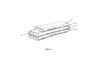
[0037] Fig. 1 and Fig. 2 shows a sectional view of exemplary building modules
1 which are
placed one over another. The building modules 1 of Fig. 2 also have barbed
wires to pin
down the building modules for securely closing them, and also binds modules
together to
provide strength to the structure. In Fig. 1, the subsequent buildings to
module 1 applies
pressure to building module 1 beneath it, to provide resistance to hold the
folds for keeping
the building modules wrapped. Either of the exemplary modules of Fig.1 or Fig.
2 can be
used, however the building modules 1 with barbed wires as in Fig. 2 have a
definite
advantage, because the barbed wire not only just holds the wraps, but also
provides bonding
between the building modules 1, and can also be employed to functionally
couple the fabric
sheet to a manufacturing device.
[0038] These building modules 1 are made of fabric sheets 2, which wrap around
the filling
material 3 to form folds over the filling material 3, with edges 5 of the
wrap's folds are further
held by a holding means 4. The holding means 4 in Fig.1 exemplary building
module 1 is
pressure applied by a subsequent building module 1, and in Fig. 2 exemplary
embodiment
is the barbed wires 6.
[0039] The fabric sheet 2 has edges 5 which are folded up and over the filling
material, one
edge of the fabric over the other. Also, the filling material 3 inside the
wrap is compressed
or compacted to provide stability to the building module 1.
CA 03206292 2023- 7- 25
WO 2022/155711
PCT/AU2022/050032
11
[0040] The fabric sheet can be of synthetic material or natural fibre
material. Even a
composite material of synthetic material and natural fibre material can also
be used.
Synthetic material can be any plastic, polythene or synthetic fibre such as
fibreglass or
metallic threads. The natural fibres are preferred in a scenario where
structures are required
to return the structure back to earth in an environmentally friendly way. One
such great
example of natural fibre material is hessian (linen/burlap). When rendered, it
becomes
permanent, and if left un-rendered or if the render is broken up, it will rot
into the earth, which
is great for temporary structures like formwork, shoring or damming. It is
pertinent to be
noted that any other kind of fabric material can also be used, however, the
material used
should have tensile strength.
[0041] The holding means 4 can be a stitching means or an adhesive, or a
pinning means,
or another building module kept over this module and any combination of the
holding means
4 can be used to further strengthen holding capacity of the wraps. The
stitching means and
the pinning means are affixed to the wrap and penetrate both layers, as shown
by the barbed
wires in Fig. 2. The adhesive is provided between two layers of the wrap, so
as to bind the
two layers together. Adhesives can also be used between
courses/modules/voussoirs.
[0042] The filling material can be sand, silt, clay, gravel, other types of
earth material,
organic material, recycled waste, bonding agents, and any combination of these
types of
filling materials. In one exemplary implementation, for walls, a formula of
25% sand, 25%
clay, 25% silt and 25% gravel is ideal. In some other embodiments, a mixture
including 10%
cement can be used in filling material 3. It is pertinent to note that each of
the filling materials
have their own utility and advantages, which are mentioned further. Clay,
glues, proteins,
lime, fibres and cement add cohesiveness because they glue particulates
together. The
other aggregates (silt, sand, gravel) stop clay from being too reactive
(swelling with humid
conditions and shrinking when dry). Sand and gravel add compressive strength.
Cement
and lime add permanent, waterproof cohesiveness. Organic materials are avoided
unless
the structure is to be impermanent, but they can be useful for adding tensile
strength, for
example, fibre (straw, chaff, chopped fabric) has been used in earth building
since time
immemorial.
CA 03206292 2023- 7- 25
WO 2022/155711
PCT/AU2022/050032
12
[0043] Bonding agents can be lime, clay, cement, proteins, gypsum, fibre,
glue, or
combination of any of these bonding agents. Bonding agents provide permanent
cohesiveness. They turn the wrap into a block as they set. Some of these
materials are
naturally present in mineral earth (like clay, lime), and the earth may need
adjusting to get
the profile 'right'. This means special earths and agents might need to be
added, and others
sieved out. In the earth building industry, purists like to avoid chemical
impurities like cement
because of the relatively high carbon-footprint, added cost and the industrial
processes
involved. But engineers and authorities tend to like them because they add a
safety factor
to the technology.
[0044] It is pertinent to note that the building modules 1 can be indefinitely
long. Even longer
than a wall, if the wall is to have rounded corners or is a dome of sorts, in
which case the
whole structure can potentially be a single 'spiral'.
[0045] In one embodiment, a building module 1 can be extended beyond the cut
length of
the first fabric sheet 2 by adding additional fabric sheets 2. Near the end of
the first fabric
sheet, a second fabric sheet starts and is wrapped with the first as if they
were one. Both
the first fabric sheet and the second fabric sheet wrap around the filling
material together
and the edges of at least one of the wraps are held by the holding means. This
embodiment
is helpful to extend building modules so that modules are not limited by
lengths of the fabric
sheet.
[0046] Fig. 3 shows a representation of a manual method to make the building
modules. It
involves laying a fabric sheet 2 over an existing course of building module 1,
over the ground,
floor or over a foundation. The sheets don't have to be continuous to deliver
a continuous
product. When one sheet ends, another can overlap it to continue. A bottomless
container
8 is placed over the course. The container is filled with earth, sand or some
other filling
material 3. The filling material is compacted to structurally satisfactory
levels using a
compressing means 9, such as a tamper, a compactor, vibration or even by
adding a fluid.
One example of fluid as compacter/compressor is water, which needs to be added
in any
case, if the cohesion ingredient is cement, lime or another water-activated
media. The first
sheet edge 5 is folded in, then the second edge 5, then the wraps are pinned
down with pins
CA 03206292 2023- 7- 25
WO 2022/155711
PCT/AU2022/050032
13
7. Other holding means for holding the edges can be spikes, pegs, barbed wire,
glue,
stitching etc. The container 8 is then pulled forward to advance the process.
[0047] The technique of the invention can be implemented through a full
mechanized device
or semi-mechanized device. The device may include a filling means and a
folding means.
The filling means includes a top part having a top opening and a bottom part
having a bottom
opening. Through the top opening, the filling material or a composite of the
filling material
and a bonding agent is filled through the bottom opening onto a fabric sheet.
The folding
means fold edges of the fabric sheet on one over another when the filling
material or the
composite of the filling material and the bonding agent (if any is used) is
placed onto the
fabric sheet. Further procedure for compressing the filling material and
fixing the edges of
the fibre sheet one over another to hold the folds can be carried out manually
or using further
mechanisation.
[0048] In another embodiment, the device is also provided with a compressing
means, which
compresses the filling material when it is placed onto the fabric sheet
through the filling
means.
[0049] In one embodiment, the device is also provided with a holding means
adapted to seal
the wrap formed by the folding ends of the fabric sheet. The sealing is
carried out using an
adhesive, a pinning means or stitching means, or combination thereof. The
stitching means
and the pinning means are affixed on edges the wrap and penetrating both
edges, while the
adhesive is provided between two edges of the wrap.
[0050] Fig. 4 illustrates an exemplary semi-mechanised device 10 which is
being used to
make the building modules 1. This device 10 has a container 8 which is the
filling means.
This container has a top part having a top opening and a bottom part having a
bottom
opening. Through the top opening, a filling material is filled through the
bottom opening onto
a fabric sheet. This device 10 also has a folding means 11 which has two walls
12a, 1 2b.
These walls 12a, 1 2b allow the filling means 8 to slide between the walls
12a, 12b leaving
a narrow gap to allow for the sides of the fabric sheet 2 to pass through. The
walls 12a, 12b
fold over, to become a folding means 11. These are slidable over a base or a
previous
course of the building module 1. The folding means 11 might also include one
or more pairs
CA 03206292 2023- 7- 25
WO 2022/155711
PCT/AU2022/050032
14
of guiding means 13 coupled to the walls 12a, 12b of the folding means 11 and
allows the
device 10 to be easily placed directly over a base or a previous course of the
building module
1. In an alternate embodiment, the walls 12a, 12b need not be slidable on the
previous
course, rather the walls 12a, 12b are placed on to the previous course of one
of the building
module or foundation, and in such scenario, the user of the device has to
apply their skills
to appropriately move the device to place and create the building module. In
one
embodiment, the guiding means 13 are not provided, and the user has to use
their skills for
placing the device 10 over a base or a previous course of the building module
1.
[0051] Fig. 5 illustrates a fully mechanised device 10 which is being used to
make the
building modules 1. It is a device 10 that has out-stretched flanges 14a, 14b
at the front.
These flanges 14a, 14b then turn upwards in the middle, and over one another
at the back.
The device 10 is bottomless at the middle and rear sections. The front of the
device 10 is
essentially a horizontal plane. It both spreads out a fabric sheet 2 and
pushes the barbs of
barbed wire 6 into the edges 5 of the fabric sheet 2 to make them graspable by
the flanges
14a, 14b. In the middle (the next part) of the flange-machine, the flanges
14a, 14b turn
upwards (here there is no bottom, just the stretched fabric 2). This open-
handed U-shape,
behaves like a container for the filling means above, enabling the filling of
the filling material
3 conveniently and evenly. The filling material 3 is poured into the U-shape
in the fabric
sheet 2 and it can then be immediately compacted using a compressing roller
15, from both
above, and from the flanges 14a, 14b to the sides. The flanges 14a, 14b, and
with them the
sheet's edges 5, fold over one another, at which point a pin pushing roller 21
pushes the
barbed wire 6 through the opposite folds of the fabric sheet 2 (one under, one
over), thereby
securing the fabric wrap in place around the compressed fill and directly
above the previous
course or base.
[0052] For compressing the filling material, a compressing roller 15 is
provided which
compresses the filling material 3 from above when it is placed onto the fabric
sheet 2. In an
alternate embodiment, for compressing the filling material, one or more
vibrating compactors
can be provided which compresses the material through vibration mechanism. The
compressing roller 15 shall be heavy in weight and may additionally have
spring-loading.
CA 03206292 2023- 7- 25
WO 2022/155711
PCT/AU2022/050032
[0053] The device 10 also includes a pinning roller 17 with one or more
grooves 18 which
allows barbs of a barbed wire 6 to pass through and to pierce and embed the
barbs into
fabric layers, and yet still protrude sufficiently to hold subsequent courses
of a previous
building module 1.
[0054] The device further includes one or more spools 19 which hold the barbed
wire 6 and
is functionally coupled to the pinning rollers 17, such that when the device
10 moves, the
spools 19 supply the barbed wire 6 to be continuously attached to the fabric
sheet 2 by the
set of pinning rollers 17.
[0055] The device also includes a sheet holder 20 which holds the fabric sheet
2 and is
functionally coupled to the pinning rollers 17, such that when the device 10
moves, the sheet
holder 20 passes on the fabric sheet 2 to the pinning rollers 17.
[0056] The filling can be carried out using an attached or separate unit. The
filling can be
carried by a person with a shovel, bucket or another manual device manually.
However, to
make the device completely automatic, a conveyor running from underneath a
material
hopper would be a good solution. Alternatively, the filling material can fall
out of a hopper
directly.
[0057] The device 10 can be moved by an external propulsion mechanism. A
coupling 16
to which said external propulsion mechanism shall be connected, is provided
onto the device
10.
[0058] According to another embodiment of the invention, there is provided a
building
module (1) consisting of a fabric sheet (2) wrapping around a filling material
(3) in a spiral
configuration, and held in place by a holding means (4). Folds are formed
around the filling
material (3) about each turn of the spiral. The edges (5) of the wrap's folds
overlap along
substantially each consecutive turn of the spiral, as held in place by the
holding means (4).
[0059] Accordingly there is provided a building module (1) wherein the folds
run oblique to
an axis of the building module (1), the overlapping edges (5) run oblique to
an axis of the
CA 03206292 2023- 7- 25
WO 2022/155711
PCT/AU2022/050032
16
building module (1), and the holding means (4) run oblique to the axis of the
fabric sheet (2)
and to the overlapping edges (5).
[0060] It is worth saying that the wrap technique, used in the current
invention, is more
robust if finished with a render of some kind because plastics and natural
fibres may be
subject to deterioration in UV radiation (from sunlight), fire or physical
damage. Paint can
help with UV, and some coatings with fire also, but render is best. Render
isn't required for
temporary walls, except to further stave off fire.
[0061] The modules can be used to form various kind of structures like
building construction,
landscapes, emergency structures, and many other types of structures. Some
examples of
building construction are walls, ground slabs, domes, cupolas, vaults, arches.
Some
examples of landscape uses are retaining walls, temporary retaining walls and
terracing,
planters, fencing/ farm walls, dykes, dams, water breaks, sea walls,
irrigation channels,
windbreaks, erosion control, soil stabilization structures, structures in
place of gabions, and
plant trails (where sets are pre-mixed into organic earth and there the fabric
'breathable' or
organic). Some examples of emergency structures are fire breaks and flood
levies. Other
types of structures can include water tanks, silos, septic systems,
construction on the lunar
surface and other solid planets, and inexpensive mass (for counterweights
etc.).
CA 03206292 2023- 7- 25
WO 2022/155711
PCT/AU2022/050032
17
LIST OF REFERENCE NUMERALS
1 Building Module
2 Fabric Sheet
3 Filing Material
4 Holding Means
Edges of Wrap
6 Barbed Wires
7 Pins
8 Container, Filling means
9 Compressing means
Device
11 Folding means
12a, 12b Walls of the folding means
13 Guiding means
14a, 14b Flanges
Compressing Rollers
16 Coupling for external propulsion mechanism
17 Pinning Rollers
18 Grooves of Pinning rollers
19 Spools
Sheet Holder
21 Pin Pushing Roller
CA 03206292 2023- 7- 25