Note: Descriptions are shown in the official language in which they were submitted.
WO 2022/157731
PCT/IB2022/050597
1
CONDITIONAL SYNCHRONIZATION SIGNAL BLOCK
MEASUREMENT TIME CONFIGURATION IN NON-TERRESTRIAL
NETWORKS.
TECHNICAL FIELD
The present disclosure relates, in general, to wireless communications and,
more particularly, systems and methods for conditional Synchronization Signal
Block
Measurement Time Configuration (SMTC) in Non-Terrestrial Networks.
BACKGROUND
Third Generation Partnership Project (3GPP) specifies the Evolved Packet
System (EPS). EPS is based on the Long-Term Evolution (L ___ IL) radio network
and
the Evolved Packet Core (EPC). EPS was originally intended to provide voice
and
Mobile Broadband (MBB) services but has continuously evolved to broaden its
functionality. 3GPP also specifies narrowband Internet of Things (NB-IoT) and
LTE
for machines (LTE-M) as part of the LTE specifications and provide
connectivity to
Massive Machine Type Communications (mMTC) services.
3GPP also specifies the 5G system (5GS). This is anew generation radio access
technology intended to serve use cases such as Enhanced Mobile Broadband
(eMBB),
Ultra-Reliable and Low Latency Communication (URLLC) and mMTC. 5G includes
the New Radio (NR) access stratum interface and the 5G Core Network (5GC). The
NR physical and higher layers reuse parts of the LTE specification, and to
that add
needed components when motivated by the new use cases. One such component is a
sophisticated framework for beam forming and beam management to extend the
support of the 3GPP technologies to a frequency range going beyond 6 GHz.
In 3GPP Release 15, 3GPP started the work to prepare NR for operation in a
Non-Terrestrial Network (NTN) (e.g., satellite communications). The work was
performed within the study item "NR to support Non-Terrestrial Networks" and
resulted in 3GPP TR 38.811. In 3GPP Release 16, the work to prepare NR for
operation in an NTN network continued with the study item "Solutions for NR to
support Non-Terrestrial Network". In parallel, the interest to adapt NB-IoT
and LTE-
CA 03206338 2023- 7- 25
WO 2022/157731
PCT/IB2022/050597
2
M for operation in NTN is growing. As a consequence, 3GPP Release 17 contains
both
a work item on NR NTN and a study item on NB-IoT and LTE-M support for NTN.
A satellite radio access network usually includes the following components. A
satellite that refers to a space-borne platform. An earth-based gateway that
connects
the satellite to a base station or a core network, depending on the choice of
architecture.
A feeder link that refers to the link between a gateway and a satellite. An
access link
that refers to the link between a satellite and a UE.
Depending on the orbit altitude, a satellite may be categorized as low earth
orbit (LEO), medium earth orbit (MEO), or geostationary earth orbit (GEO)
satellite.
LEO includes typical heights ranging from 250 ¨ 1,500 km, with orbital periods
ranging from 90 ¨ 120 minutes. MEO includes typical heights ranging from 5,000
¨
25,000 km, with orbital periods ranging from 3 ¨ 15 hours. GEO includes height
at
about 35,786 km, with an orbital period of 24 hours.
A communication satellite typically generates several beams over a given area.
The footprint of a beam is usually in an elliptic shape, which has been
traditionally
considered as a cell. The footprint of a beam is also often referred to as a
spotbeam.
The footprint of a beam may move over the earth surface with the satellite
movement
or may be earth fixed with some beam pointing mechanism used by the satellite
to
compensate for its motion. The size of a spotbeam depends on the system
design,
which may range from tens of kilometers to a few thousands of kilometers.
Two basic architectures have been considered. One is the transparent payload
(also referred to as bent pipe architecture). In this architecture, the gNodeB
(gNB) is
located on the ground and the satellite forwards signals/data between the gNB
and the
UE. Another is the regenerative payload. In this architecture, the gNB is
located in the
satellite. In the work item for NR NTN in 3GPP Release 17, only the
transparent
architecture is considered.
FIGURE 1 illustrates an example architecture of a satellite network with bent
pipe transponders. The gNB may be integrated in the gateway or connected to
the
gateway via a terrestrial connection (wire, optic fiber, wireless link).
Propagation delay is an important aspect of satellite communications that is
different from the delay expected in a terrestrial mobile system. For a bent
pipe satellite
CA 03206338 2023- 7- 25
WO 2022/157731
PCT/1B2022/050597
3
network, the round-trip delay may, due to the orbit height, range from tens of
ms in
the case of LEO to several hundreds of ins for GEO. This can be compared to
the
round-trip delays catered for in a cellular network which are limited to 1 ms.
The distance between the user equipment (UE) and a satellite can vary
significantly, depending on the position of the satellite and thus the
elevation angle a
seen by the UE. Assuming circular orbits, the minimum distance is realized
when the
satellite is directly above the UE (a = 90"), and the maximum distance when
the
satellite is at the smallest possible elevation angle. Table 1 shows the
distances
between satellite and UE for different orbital heights and elevation angles
together
with the one-way propagation delay and the maximum propagation delay
difference
(the difference towards a = 90 ). Table 1 assumes regenerative architecture.
For the
transparent case, the propagation delay between gateway and satellite needs to
be
considered as well, unless the base station corrects for that.
Table 1: Propagation delay for different orbital heights and elevation angles.
Orbital Elevation Distance
One-way Propagation
height angle UE <-> satellite propagation
delay delay
difference
600 km 90 600 km 2.0 ms
300 1075 km 3.6 ms 1 1.6 ms
100 1932 km 6.4 ms 4.4 ms
1200 km 90 1200 km 4.0 ins
30 1999 km 6.7 ms 2.7 ms
10 3131 km 10.4 ms 6.4 ms
35786 km 90 35786 km 119.4 ms
30 38609 km 128.8 ms 9.4 ms
100 40581 km 135.4 ms 16.0 ms
The propagation delay may also be highly variable due to the high velocity of
the LEO and MEO satellites and change in the order of 10 ¨ 100 vis every
second,
depending on the orbit altitude and satellite velocity.
CA 03206338 2023- 7- 25
WO 2022/157731
PCT/1B2022/050597
4
In the context of propagation delay, the timing advance (TA) the UE uses for
its uplink transmissions is essential and has to be much greater than in
terrestrial
networks for the uplink and downlink to be time aligned at the gNB, as is the
case in
NR and LTE. One of the purposes of the random access (RA) procedure is to
provide
the UE with a valid TA (which the network later can adjust based on the
reception
timing of uplink transmission from the UE). However, even the random access
preamble (i.e., the initial message from the UE in the random access
procedure) has to
be transmitted with a timing advance to allow a reasonable size of the RA
preamble
reception window in the gNB, but this TA does not have to be as accurate as
the TA
the UE subsequently uses for other uplink transmissions. The TA the UE uses
for the
RA preamble transmission is called "pre-compensation TA". Various proposals
are
considered for how to determine the pre-compensation TA, all of which involves
information originating both at the gNB and at the UE.
One proposal is broadcast of a "common TA- which is valid at a certain
reference point, e.g., a center point in the cell. The UE then calculates how
its own
pre-compensation TA deviates from the common TA, based on the difference
between
the UE' s own location and the reference point together with the position
ofthe satellite.
Herein, the UE acquires its own position using Global Navigation Satellite
System
(GNSS) measurements and the UE obtains the satellite position using satellite
orbital
data (including satellite position at a certain time) broadcast by the
network.
According to another proposal, the UE autonomously calculates the
propagation delay between the UE and the satellite based on the UE's and the
satellite's respective positions, and the network/gNB broadcasts the
propagation delay
on the feeder link, i.e., the propagation delay between the gNB and the
satellite. The
UE may acquire its own position using GNSS measurements, and the UE may obtain
the satellite position using satellite orbital data (including satellite
position at a certain
time) broadcast by the network. The pre-compensation TA is then twice the sum
of the
propagation delay on the feeder link and the propagation delay between the
satellite
and the UE.
In another proposal, the gNB broadcasts a times-tamp (in SIB9), which the UE
compares with a reference timestamp acquired from GNSS. Based on the
difference
CA 03206338 2023- 7- 25
WO 2022/157731
PCT/1B2022/050597
between these two timestamps, the UE can calculate the propagation delay
between
the gNB and the UE, and the pre-compensation TA is twice as long as this
propagation
delay.
A second important aspect closely related to the timing is a Doppler frequency
5 offset induced by the motion of the satellite. The access link may be
exposed to
Doppler shift on the order of 10 ¨ 100 kHz in sub-6 GHz frequency band and
proportionally higher in higher frequency bands. Also, the Doppler shift is
varying,
with a rate of up to several hundred Hz per second in the S-band and several
kHz per
second in the Ka-band.
A global navigation satellite system comprises a set of satellites orbiting
the
earth in orbits crossing each other, such that the orbits are distributed
around the globe.
The satellites transmit signals and data that facilitates a receiving device
on earth to
accurately determine time and frequency references and accurately determine
its
position, provided that signals are received from a sufficient number of
satellites (e.g.,
four). The position accuracy may typically be in the range of a few meters,
but using
averaging over multiple measurements, a stationary device may achieve much
better
accuracy.
A well-known example of a GNSS is the American Global Positioning System
(GPS). Other examples are the Russian Global Navigation Satellite System
(GLONASS), the Chinese BeiDou Navigation Satellite System and the European
The transmissions from GNSS satellites include signals that a receiving device
uses to determine the distance to the satellite. By receiving such signals
from multiple
satellites, the device can determine its position. However, this requires that
the device
also knows the positions of the satellites. To enable this, the GNSS
satellites also
transmit data about their own orbits (from which position at a certain time
can be
derived). In GPS, such information is referred to as ephemeris data and
almanac data
(or sometimes lumped together under the term navigation information).
The time required to perform a GNSS measurement, e.g. GPS measurement,
may vary widely, depending on the circumstances, mainly depending on the
status of
the ephemeris and almanac data the measuring devices has previously acquired
(if
CA 03206338 2023- 7- 25
WO 2022/157731
PCT/1B2022/050597
6
any). In the worst case, a GPS measurement can take several minutes. GPS is
using a
bit rate of 50 bps for transmitting its navigation information. The
transmission of the
GPS date, time and ephemeris information takes 90 seconds. Acquiring the GPS
Almanac containing orbital information for all satellites in the GPS
constellation takes
more than 10 minutes. If a UE already possesses this information, the
synchronization
to the GPS signal for acquiring the UE position and Coordinated Universal Time
(UTC) is a significantly faster procedure.
3GPP NTN is dependent on GNSS. To handle the timing and frequency
synchronization in a NR- or LTE-based NTN, a promising technique is to equip
each
device with a GNSS receiver. The GNSS receiver facilitates a device to
estimate its
geographical position. In one example, a NTN gNB carried by a satellite
broadcasts
its ephemeris data (i.e., data that informs the UE about the satellite's
position, velocity
and orbit) to a GNSS equipped UE. The UE can then determine the propagation
delay,
the delay variation rate, the Doppler shift and its variation rate based on
its own
location (obtained through GNSS measurements) and the satellite location and
movement (derived from the ephemeris data).
The GNSS receiver also facilitates a device to determine a time reference
(e.g.,
in terms of UTC) and frequency reference. This can also be used to handle the
timing
and frequency synchronization in a NR or LTE based NTN. In a second example, a
NTN gNB carried by a satellite broadcasts its timing (e.g., in terms of a
Coordinated
Universal Time (UTC) timestamp) to a GNSS equipped UE. The UE can then
determine the propagation delay, the delay variation rate, the Doppler shift,
and its
variation rate based on its time/frequency reference (obtained through GNSS
measurements) and the satellite timing and transmit frequency.
The UE may use this knowledge to compensate its uplink transmissions for the
propagation delay and Doppler effect.
With respect to NB-IoT and LTE-M for NTN, 3GPP specifications note that
GNSS capability in the UE is taken as a working assumption for both NB-IoT and
cMTC devices. With this assumption, a UE can estimate and pre-compensate
timing
and frequency offset with sufficient accuracy for uplink transmission.
Simultaneous
GNSS and NTN NB-IoT/eMTC operation is not assumed.
CA 03206338 2023- 7- 25
WO 2022/157731
PCT/1B2022/050597
7
Furthermore, in the NTN work item and IoT NTN study item for 3GPP Release
17, GNSS capability is assumed. For example, it is assumed that a NTN capable
UE
also is GNSS capable and GNSS measurements at the UEs are essential for the
operation of the NTN.
NR also includes SSB-MTC and measurement gaps. NR synchronization
signal (SS) consists of primary SS (PSS) and secondary SS (SSS). NR physical
broadcast channel (PBCH) carries the very basic system information. The
combination
of SS and PBCH is referred to as SSB in NR. Multiple SSBs are transmitted in a
localized burst set. Within a SS burst set, multiple SSBs can be transmitted
in different
beams. The transmission of SSBs within a localized burst set is confined to a
5 ms
window. The set of possible SSB time locations within an SS burst set depends
on the
numerology which in most cases is uniquely identified by the frequency band.
The
SSB periodicity can be configured from the value set {5, 10, 20, 40, 80, 160}
ms.
A UE does not need to perform measurements with the same periodicity as the
SSB periodicity. Accordingly, the SSB measurement time configuration (SMTC)
has
been introduced for NR. The signaling of SMTC window informs the UE of the
timing
and periodicity of SSBs that the UE can use for measurements. The SMTC window
periodicity can be configured from the value set {5, 10, 20, 40, 80, 160} ms,
matching
the possible SSB periodicities. The SMTC window duration can be configured
from
the value set {1, 2, 3, 4, 5} ms.
The UE may use the same radio frequency (RF) module for measurements of
neighboring cells and data transmission in the serving cell. Measurement gaps
enable
the UE to suspend the data transmission in the serving cell and perform the
measurements of neighboring cells. The measurement gap repetition periodicity
can
be configured from the value set {20, 40, 80, 160} ms, the gap length can be
configured
from the value set {1.5, 3, 3.5, 4, 5.5, 6} ms. Usually, the measurement gap
length is
configured to be larger than the SMTC window duration to account for RF
retuning
time. Measurement gap time advance is also introduced to fine tune the
relative
position of the measurement gap with respect to the SMTC window. The
measurement
gap timing advance can be configured from the value set {0, 0.25, 0.5} ms.
CA 03206338 2023- 7- 25
WO 2022/157731
PCT/1B2022/050597
8
FIGURE 2 illustrates an example of SSB, SMTC window, and measurement
gap. Section 5.5.2.10 in 3GPP TS 38.331 specifies SMTC configuration as
follows:
The IJE shall setup the first SS/PBCH block measurement timing
configuration (SMTC) in accordance with the received
periodicityAndOffset parameter (providing Periodicity and Offset value
for the following condition) in the smtc/ configuration. The first
subframe of each SMTC occasion occurs at an SFN and subframe of the
NR SpCell meeting the following condition:
SFN mod T= (FLOOR (Offset110));
if the Periodicity is larger than sf 5:
subframe = Offset mod 10;
else:
subframe = Offset or (Offset +5);
with T = CEIL(Periodicny110).
If smtc2 is present, for cells indicated in the pci-List parameter in smtc2
in the same MectsObjectNR, the UE shall setup an additional SS/PBCH
block measurement timing configuration (SMIC) in accordance with
the received periodicity parameter in the smtc2 configuration and use
the Offset (derived from parameter periodicityAnc/Offset) and duration
parameter from the srntc/ configuration. The first subframe of each
SMTC occasion occurs at an SFN and subframe of the NR SpCell
meeting the above condition.
If smtc2-LP is present, for cells indicated in the pci-List parameter in
smtc2-LP in the same frequency (for intm frequency cell reselection) or
different frequency (for inter frequency cell reselection), the UE shall
setup an additional SS/PBCH block measurement timing configuration
(SMTC) in accordance with the received periodicity parameter in the
smtc2-LP configuration and use the Offset (derived from parameter
CA 03206338 2023- 7- 25
WO 2022/157731
PCT/1B2022/050597
9
periodicityAndOlfset) and duration parameter from the smtc
configuration for that frequency. The first subframe of each SMTC
occasion occurs at an SFN and subframe of the NR SpCell or serving
cell (for cell reselection) meeting the above condition.
On the indicated ssbFrequency, the UE shall not consider SS/PBCH
block transmission in subframes outside the SMTC occasion for RR_M
measurements based on SS/PBCH blocks and for RRM measurements
based on CSI-RS except for SFTD measurement (see 3GPP TS 38.133,
subclause 9.3.8).
There currently exist certain challenges. For example, SMTC and the different
variants thereof are efficient means to facilitate for a UE to find relevant
SSB
transmissions and to limit the SSB search and measurement effort in
terrestrial
networks. However, the special properties of NTNs impose problems that are not
present in terrestrial networks and which the existing SMTC definition is not
adapted
to deal with.
For example, consider the scenario where the network that serves the UE is a
LEO satellite network with a significant amount of transparent satellites at
600 km
altitude, in the range of thousands of satellites that orbit the earth,
providing
connectivity the UEs on earth. The UE is located at (long, lat) = (xl,y1) and
the ground
gateway, i.e., the gNB that receives the signal is located at (long, lat) =
(x2,y2), which
is a typical scenario. For example, FIGURE 3 illustrates an example of the
round-trip
propagation delay from the UE to the satellite/gNB (which is the propagation
delay
from UE to satellite to ground gateway) as function of time for a stationary
UE. Each
line represents the propagation delay to a gNB on the ground through a
satellite.
FIGURE 3 reveals that there will be a lot of satellites at varying propagation
delays compared to the satellite with the smallest propagation delay. Because
the
propagation delay is related to the distance from the UE to the satellite, the
satellite
with the lowest propagation delay is also typically the satellite that the UE
will have
the strongest signal to, although that might not always be the case.
CA 03206338 2023- 7- 25
WO 2022/157731
PCT/1B2022/050597
Even though there are a large number of satellites, the number of interesting
satellites to which the UE may connect is not necessarily that large.
Furthermore, with
the network being aware of both the satellite orbit as well as the UE
position, it is
possible for the network to know which satellite or satellites whose cells
that the UE
5 should choose from.
As seen from FIGURE 3, the network may configure the UE to measure and
track a set of satellites, which corresponds to a set of cells, which further
corresponds
to a set of physical cell identities (PCIs) (included in SSBs), the UE would
likely have
to track the SSBs and, due to the satellites' movements with resulting
changing
10 propagation delays, measure far outside of the measurement
windows that are defined
through SMTC and measurement gaps.
SUMMARY
Certain aspects of the present disclosure and their embodiments may provide
solutions to these or other challenges. Particular embodiments include UE
embodiments.
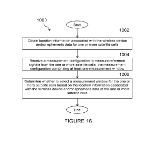
According to certain embodiments, a method by a wireless device includes
obtaining location information associated with the wireless device and/or
ephemeris
data for one or more satellite cells. The wireless device receives a
measurement
configuration to measure reference signals from the one or more satellite
cells, and the
measurement configuration comprising at least one measurement window. The
wireless device determines whether to selecl a measurement window for the one
or
more satellite cells based on the location information associated with the
wireless
device and/or ephemeris data of the one or more satellite cells.
According to certain embodiments, a wireless device is adapted to obtain
location information associated with the wireless device and/or ephemeris data
for one
or more satellite cells. The wireless device is further adapted to receive a
measurement
configuration to measure reference signals from the one or more satellite
cell. The
measurement configuration comprising at least one measurement window. The
wireless device is adapted to determine whether to select a measurement window
for
CA 03206338 2023- 7- 25
WO 2022/157731
PCT/1B2022/050597
11
the one or more satellite cells based on the location of the wireless device
and/or the
ephemeris data for the one or more satellite cells.
Certain embodiments may provide one or more of the following technical
advantages. For example, particular embodiments reduce the need for extended
SMTC
windows, thereby facilitating greater scheduling flexibility in the serving
cell, and can
further reduce the amount of required measurements due to the SMTC window(s)
not
always containing any SSB transmission(s) to measure on, thus reducing UE
power
consumption.
Other advantages may be readily apparent to one having skill in the art.
Certain
embodiments may have none, some, or all of the recited advantages.
BRIEF DESCRIPTION OF DRAWINGS
For a more complete understanding of the disclosed embodiments and their
features and advantages, reference is now made to the following description,
taken in
conjunction with the accompanying drawings, in which:
FIGURE 1 illustrates an example architecture of a satellite network with bent
pipe transponders;
FIGURE 2 illustrates an example of SSB, SMTC window, and measurement
gap;
FIGURE 3 illustrates an example of the round-trip propagation delay as
function of time for a stationary UE;
FIGURE 4 illustrates an example of measuring SSBs inside and outside SMTC
window, according to certain embodiments;
FIGURE 5 illustrates an example wireless network, according to certain
embodiments;
FIGURE 6 illustrates an example network node, according to certain
embodiments;
FIGURE 7 illustrates an example wireless device, according to certain
embodiments;
FIGURE 8 illustrate an example user equipment, according to certain
embodiments;
CA 03206338 2023- 7- 25
WO 2022/157731
PCT/1B2022/050597
12
FIGURE 9 illustrates a yirtualization environment in which functions
implemented by some embodiments may be yirtualized, according to certain
embodiments;
FIGURE 10 illustrates a telecommunication network connected via an
intermediate network to a host computer, according to certain embodiments;
FIGURE 11 illustrates a generalized block diagram of a host computer
communicating via a base station with a user equipment over a partially
wireless
connection, according to certain embodiments;
FIGURE 12 illustrates a method implemented in a communication system,
according to one embodiment;
FIGURE 13 illustrates another method implemented in a communication
system, according to one embodiment;
FIGURE 14 illustrates another method implemented in a communication
system, according to one embodiment;
FIGURE 15 illustrates another method implemented in a communication
system, according to one embodiment; and
FIGURE 16 illustrates an example method by a wireless device, according to
certain embodiments.
CA 03206338 2023- 7- 25
WO 2022/157731
PCT/1B2022/050597
13
DETAILED DESCRIPTION
Some of the embodiments contemplated herein will now be described more
fully with reference to the accompanying drawings. Other embodiments, however,
are
contained within the scope of the subject matter disclosed herein, the
disclosed subject
matter should not be construed as limited to only the embodiments set forth
herein;
rather, these embodiments are provided by way of example to convey the scope
of the
subject matter to those skilled in the art. Although particular problems and
solutions
may be described using new radio (NR) terminology, it should be understood
that the
same solutions apply to long term evolutions (LTE) and other wireless networks
as
well, where applicable.
Generally, all terms used herein are to be interpreted according to their
ordinary
meaning in the relevant technical field, unless a different meaning is clearly
given
and/or is implied from the context in which it is used. All references to
a/an/the
element, apparatus, component, means, step, etc. are to be interpreted openly
as
referring to at least one instance of the element, apparatus, component,
means, step,
etc., unless explicitly stated otherwise. The steps of any methods disclosed
herein do
not have to be performed in the exact order disclosed, unless a step is
explicitly
described as following or preceding another step and/or where it is implicit
that a step
must follow or precede another step. Any feature of any of the embodiments
disclosed
herein may be applied to any other embodiment, wherever appropriate. Likewise,
any
advantage of any of the embodiments may apply to any other embodiments, and
vice
versa. Other objectives, features and advantages of the enclosed embodiments
will be
apparent from the following description.
The embodiments outlined below are described mainly in terms of NR based
Non-Terrestrial Networks (NTNs), but they are equally applicable in a NTN
based on
LTE technology or any other radio access technology (RAT) where measurement
windows and gaps may be configured.
Particular examples focus on Synchronization Signal Block Measurement
Time Configuration (SMTC) and SMTC window configuration and corresponding
measurement gaps, but embodiments are equally applicable if the SMTC
configuration
is replaced by Received Signal Strength Indicator Measurement Timing
Configuration
CA 03206338 2023- 7- 25
WO 2022/157731
PCT/1B2022/050597
14
(RMTC) or measurement timing configuration for any other reference signal or
other
type of m easurable signal (e.g., a signal suitable for channel quality
measurement).
In the following, the following actions might be used interchangeably: 1)
measuring a satellite, 2) measuring SSB(s), and/or 3) measuring neighboring
cells(s).
In general, it can be said that a single satellite might have multiple cells,
a cell has a
PCI, and a cell may transmit multiple SSBs. It is assumed that there are PCI-
to-
satellite mapping either provided explicitly or implicitly by ephemeris data
or similar.
A further set of actions might also be used interchangeably: 1) measuring an
SSB, 2)
detecting SSB, or and/ 3) attempting to detect an SSB.
As described above, the number of satellites for which SMTC windows may
be configured may pose a problem such as, for example, in terms of
complicating and
reducing the flexibility of the scheduling in the UE's serving cell and
because it may
cause excessive measurement efforts with associated energy consumption in the
UE.
Therefore, certain embodiments may provide for reduction of the measurable
neighbor
satellites to the ones that are reasonably close. It may be argued that this
is easily
achieved if the gNB only configures SMTC windows for neighbor satellites that
are
close enough, but that would mean that the gNB would have to reconfigure the
UE
every time one of the neighbor satellites passes the propagation delay
threshold the
gNB uses internally for these decisions. For example, the gNB would have to
reconfigure the UE every time a neighbor satellite changes from being too far
away to
being close enough for measurement or vice versa. To avoid such
reconfigurations, the
UE may instead be "fully configured" at once, where the configuration includes
a
propagation delay dependent or distance dependent condition that reduces the
number
of neighbor satellites the UE actually measures on. In other words, the number
of
simultaneously "active" SMTC windows may be reduced.
To this end, certain embodiments disclosed herein associate a condition with a
configured SMTC window, and the condition may govern when the SMTC window
may be used for measurements. In particular embodiments, for example, such a
condition may be based on propagation delay or distance to a satellite whose
signals
should be measured on and which is associated with a SMTC window (e.g., such
that
CA 03206338 2023- 7- 25
WO 2022/157731
PCT/1B2022/050597
a propagation delay below a threshold, or a distance below a threshold,
"activates" the
SMTC window for measurements).
For example, in some embodiments a UE has satellite ephemeris as well as
GNSS location available. The UE receives a measurement configuration with a
list of
5 PCIs and SMTC window configurations from gNB. For each SMTC window
opportunity and for each PCI in the list of configured PCIs, the UE checks the
associated satellite for the PCI and the UE uses ephemeris information of the
satellite
associated with the PCI (and possibly its own location to be more accurate) to
determine whether the SSB of the corresponding cell would fall within this
SMTC
10 window. If yes, the UE attempts to detect and measure the SSB
within the SMTC
window. Otherwise, the UE does not attempt to detect the SSB associated with
this
PCI in this SMTC window. If none of the PCIs in the list is included in a SSB
transmission that arrives within the SMTC window, the SMTC-window instance is
skipped. The UE uses the measurement results for computation of neighboring
cell
15 signal strength.
According to certain embodiments, the network aims to configure the SMTC
window(s) such that neighbor satellites' SSB transmissions arrive within the
SMTC
window(s) when the neighbor satellites arc relatively close to the UE or UE is
relatively close to the cell border.
For example, particular embodiments associate a condition with a configured
SMTC window, where the condition governs when the SMTC window may be used
for measurements. Such a condition may be based on propagation delay or
distance to
a satellite whose signals should be measured on and which is associated with a
SMTC
window (e.g., such that a propagation delay below a threshold, or a distance
below a
threshold, "activates" the SMTC window for measurements). The condition may be
extended with a condition based on the satellite's movement direction, such
that a
satellite that is moving away from the UE does not activate the SMTC window,
regardless of the distance or propagation delay.
In some embodiments, the UE tracks the expected propagation delays of SSBs
from neighboring satellites and measures them when they are inside the SMTC
window. For example, a method for a UE to measure neighboring cells comprises:
the
CA 03206338 2023- 7- 25
WO 2022/157731
PCT/1B2022/050597
16
UE receiving its location and ephemeris data of satellite cells; the UE
receiving a
measurement configuration to measure other satellite cells from the network;
the UE
determining whether to detect a SMTC window; and the UE measuring/detecting
neighboring cell.
In some embodiments, the UE measures the SSBs of satellite cells. The UE
received configuration may be a set of PCIs and SMTC window. The UE may
determine whether to measure a specific cell based on ephemeris data and UE
location.
If the SSB is within the SMTC window, the UE may determine to measure/detect,
else
determines to not measure.
Some embodiments may include a condition related to the movement direction
of a neighbor satellite. This could be integrated in the SMTC window
activation
condition. For example, a combined condition could be that a SMTC window is
activated for measurement on signals from satellite X, if the
distance/propagation
delay to satellite X is below a threshold and the movement direction of
satellite X is
not away from the UE (where -away" from the UE could simply be defined as the
time
derivative of the distance or propagation delay between the UE and the
satellite is
greater than zero).
The movement direction may also be considered in combination with the
distance/propagation delay, such that, for example, as long as the
distance/propagation
delay is below a certain (preferably configurable) threshold, the satellite's
movement
direction may be ignored, while if the distance/propagation delay is above the
threshold, the satellite is ignored if it is moving away from the UE, even if
the
distance/propagation delay is still small enough to motivate measurement if
the
satellite was not moving away from the UE (e.g., the -regular", movement
direction
independent distance/propagation delay condition). A corresponding reasoning
may
also be applied to a satellite moving towards a UE. That is, if a satellite is
moving
towards the UE, the UE may start to measure on it even before the
distance/propagation delay to the satellite is not yet small enough to
motivate
measurement if the satellite was not moving towards the UE (e.g., the
"regular",
movement direction independent distance/propagation delay condition). When
satellite's movement direction is taken into account in these ways, the speed
with
CA 03206338 2023- 7- 25
WO 2022/157731
PCT/1B2022/050597
17
which it is approaching the UE or moving away from the UE may also be taken
into
account where this speed may be impacted, e.g., by the satellite's movement
speed
along its orbit and the horizontal distance between the UE and the satellite's
orbit's
projection on the ground.
Some embodiments may include other more complex combinations such as,
for example, involving movement direction angles, satellite speed, margin of
distance/propagation delay below the threshold, distance from the UE to the
concerned
satellite's orbit along a line perpendicular to the satellite's orbit, etc.
The movement direction condition may also be separate from the SMTC
window activation condition. For example, the gNB may not configure any SMTC
window for a neighbor satellite that is moving away from the UE. That one way
to
take the movement direction into account, but it fails to handle the situation
where a
satellite first moves towards the UE and then passes the UE to start moving
away from
it. To capture such changes, SMTC reconfigurations would be needed, which is
to be
avoided.
Two groups of example embodiments are described as follows. In a first group
of embodiments, as explained above, the difference in propagation delays
between
satellites means that when attempting to measure SSBs of other cells, the SSBs
will
end up outside of the window. According to certain embodiments, the window can
be
extended, but this has the disadvantage that, because measurement gaps must be
configured during this time, it means that less time is available for data
transmissions.
hi 3GPP (Rel-1 5), the network configures the UE with an SMTC configuration as
well
as a set of PCIs that are used to detect SSBs, whereby the UE will try to
detect the
SSBs within the SMTC. The general goal is to have as small SMTC windows as
possible to allow for more duration where data can be transmitted and for
shorter
measurement periods.
Certain embodiments enable the UE to disregard SMTC window configuration
if there are no SSBs within the window. This is done by the UE having access
to
ephemeris data that it can map to PCIs. Thus, the UE can use its location to
determine
whether the SSB of a satellite should be visible within an SMTC and thus be
measured.
CA 03206338 2023- 7- 25
WO 2022/157731
PCT/1B2022/050597
18
According to certain embodiments, the UE has satellite ephemeris as well as
GNSS location (or some approximate knowledge of location) available. In a
particular
embodiment, the UE receives a measurement configuration with a list of PCIs
and
SMTC window configurations from gNB. For each SMTC window opportunity and
for each PCI in the list of configured PCIs, the UE checks the associated
satellite for
the PCI. The UE uses ephemeris information of the satellite associated with
the PCI
(and possibly its own location to be more accurate) to determine whether the
SSB of
the corresponding cell would fall within this SMTC window. If yes, the UE
attempts
to detect and measure the SSB within the SMTC window. Otherwise, the UE does
not
attempt to detect the SSB associated with this PCI in this SMTC window. If
none of
the PCIs in the list is included in an SSB transmission that arrives within
the SMTC
window, deactivate SMTC-window opportunity.
The UE uses the measurement results for computation of neighboring cell
signal strength. FIGURE 4 illustrates an example of measuring SSBs inside and
outside SMTC window, according to certain embodiments.
For receiving the measurement configuration, the measurement configuration
can indicate a PCI-to-satellite mapping such as, for example, which satellite
is
associated with a PCI (and further to SSB), or the mapping may be implicit and
configured in advance for other purposes.
Certain embodiments have several advantages. One advantage is that there is
no need to extend the SMTC window and consequently the measurement gaps, which
facilitates easier scheduling. Another advantage is that there will be cases
where the
satellites whose SSBs/PCIs to measure are too far away to be useful to measure
and
thus outside the SMTC window(s), meaning that it is not always required to
measure
the SSB, allowing for simplification of UE procedures as well as avoiding
unnecessary
measurements when satellites and their corresponding cells are too far away to
have
any significant signal strength to be relevant. This requires that the
network, e.g. the
serving gNB, configures the SMTC window(s) with a goal to ensure that the SSB
transmissions with the listed PCIs will arrive within the SMTC window(s) when
the
transmitting satellite is close enough to be relevant.
CA 03206338 2023- 7- 25
WO 2022/157731
PCT/1B2022/050597
19
In some embodiments, it is known to the network when the UE is able to or
should measure and have the corresponding measurement gap active.
In some embodiments, there may be e.g. a rough UE location border expressed
e.g. as a distance to serving cell center or as function of the target cell.
When the UE
crosses this border, it indicates that to the network and thus the network
knows the
corresponding measurement gap becomes active and the network refrains from
scheduling to the UE.
As a further option, the gNB may exclude from the SMTC configuration, any
satellite for which the distance from the UE to the concerned satellite's
orbit along a
line perpendicular to the satellite's orbit is too long (implying that the
concerned
satellite will never be close enough to the UE to be of interest (unless the
UE moves a
long distance)).
The UE determines whether to measure a neighboring SSB if the SSB is inside
of the SMTC window (i.e., if the SSB transmission arrives to the UE within the
SMTC
window), by using ephemeris data of the satellite transmitting the SSB and the
UE's
GNSS location. This presents significant enhancements, but there may still be
room
for improvements if the ephemeris data and UE GNSS location is available.
When the satellite is moving away from the UE, the SSB of the satellite might
still be within the SMTC window due to the propagation delay being within the
SMTC
window. However, it is unlikely to be a good decision to attempt to connect to
a
satellite that is currently moving away from the UE. Thus, it is unnecessary
to continue
to detect and measure the SSB() transmitted by a satellite moving away from
the UE.
Thus, in some embodiments, when a neighbor satellite is moving away from the
UE,
the UE should not attempt to detect the satellite's SSB transmissions.
The movement direction may also be considered in combination with the
distance/propagation delay such that as long as the distance/propagation delay
is below
a certain (preferably configurable) threshold, for example, the satellite's
movement
direction may be ignored. Conversely, if the distance/propagation delay is
above the
threshold, the satellite is ignored if it is moving away from the UE. This is
done even
if the distance/propagation delay is still small enough to motivate performing
measurement.
CA 03206338 2023- 7- 25
WO 2022/157731
PCT/1B2022/050597
A corresponding reasoning may also be applied to a satellite moving towards
a UE. That is, if a satellite is moving towards the UE, the UE may start to
measure on
it even before the distance/propagation delay to the satellite is not yet
small enough to
motivate measurement if the satellite was not moving towards the UE (e.g., the
5 "regular- movement direction independent distance/propagation
delay condition).
When the satellite's movement direction is taken into account in these ways,
the speed with which it is approaching the UE or moving away from the UE may
also
be taken into account. This speed may be impacted, for example, by the
satellite's
movement speed along its orbit and the horizontal distance between the UE and
the
10 satellite's orbit's projection on the ground.
In some embodiments, in addition to distance/propagation delay, another
condition can be considered. For example, this condition may be based on the
time
that UE is expected to be serviced by a particular satellite, e.g., I service.
This
condition may be configured separately or in combination with distance and
15 propagation delay mentioned above with various combinations.
In connected mode such as, for example, a RRC_CONNECTED state, the
measurements are often used to report back to the network about the status of
neighboring cells. This can be done either autonomously or upon being
triggered.
For reporting back the measurement results of SSB measurements, for the sets
20 of SSBs/satellite cells that are in the SMTC window the results
are reported back as
normal; however, for the SSBs/satellites/cells that are outside, in one
particular
embodiment an indication is included that they were not measured. Some
embodiments include an indication that a certain SSB/PCI was not measured.
This can,
for example, be done through a flag indicating that it was not measured or
through an
-inf(minus infinity value) in the measurement value. Another option can be to
capture
in the associated field description that the absence of a measurement for
particular
SSBs/satellites/cells would mean implicitly that those were not measured due
to being
outside of the configured SMTC window. In some embodiments, for those
measurements that were made but not reported due to being less than a
configured
threshold are marked such as, for example, with a flag so that the network is
able to
CA 03206338 2023- 7- 25
WO 2022/157731
PCT/1B2022/050597
21
differentiate from those SSBs/satellites/cells that were not measured due to
being
outside of the SMTC window.
The configuration to enable the actions described above can, for example, be
signaled as either an indication in the respective measurement object, or
within the
SMTC configuration, or alternatively per PCI.
Configuring this per measurement object can, for example, allow for SMTC
windows associated with a specific measurement object to use the methods
described
above, while other measurement objects use legacy methods. This can, for
example,
allow use cases where on certain carriers, more relaxed measurement procedures
are
used to simplify UE procedures and reduce power consumption. Another use case
may
be that the legacy methods are used for measurements on cells/carriers in
terrestrial
networks, while the embodiments described herein are used for measurements on
cells/carriers in non-terrestrial networks. This use case is applicable both
when the UE
is connected in a cell in a terrestrial network and when it is connected in a
cell in a
non-terrestrial network.
To enable a UE to not measure when a neighboring satellite/SSB(s) move away
from the UE, this can, for example, be configured per PCI. This can enable the
network
to configure certain satellite(s)/cell(s)/SSB(s) that arc less likely to be
candidate(s) for
being a new serving cell to have more relaxed measurement conditions if it is
unlikely
that the satellite neighboring cell will be the strongest cell. An alternative
to
configuring this per PCI is to configure it per satellite. The latter would be
a suitable
alternative if a satellite identifier is introduced (e.g. standardized) to be
used in cases
where identification of, or reference to, a certain satellite is needed or
beneficial.
As previously mentioned, a benefit of particular embodiments is that the UE's
time domain will not be cluttered with SMTC windows for various satellites,
which
would otherwise complicate and reduce the flexibility of the scheduling of the
UE in
the serving cell.
In a second group of embodiments, reducing such cluttering may be achieved
through additions to other methods for SMTC window configuration in NTNs. Such
SMTC window configuration methods may involve that each neighbor satellite may
CA 03206338 2023- 7- 25
WO 2022/157731
PCT/1B2022/050597
22
have its own SMTC window and the UE and the gNB can adapt the SMTC windows
autonomously to the satellite movements.
In the second group of embodiments, the gNB adds to (or associates with) the
SMTC configuration, a maximum propagation delay or a maximum distance (per
neighbor satellite or common to all neighbor satellites) at which a neighbor
satellite's
SMTC window may be used for measurements. As a result, only a subset of the
configured SMTC windows will be simultaneously "active", i.e. those for which
the
associated neighbor satellites are close enough for their respective
propagation delay
or distance to be smaller than the configured maximum propagation delay or
maximum
distance. In this, the propagation delay or distance is measured between the
concerned
satellite and the UE. As an alternative, the propagation delay or distance may
be
measured between the concerned satellite and a reference location in the UE's
serving
cell.
As previously described, a satellite's movement direction (and speed with
which a satellite is moving towards the UE or away from the UE) may also be
taken
into account in the condition for activating a SMTC window.
If multiple satellites are associated with the same SMTC window, it is enough
that one of these satellites fulfill the SMTC window activation condition for
the SMTC
window to be activated. In such a scenario, as one option, the UE measures on
all the
satellites that are associated with an activated SMTC window. As another
option, when
a SMTC window is activated, the UE measures only on the associated satellites,
which
fulfill the distance/propagation (and possible movement direction and/or
speed)
condition.
As a further option, the gNB may exclude from the SMTC configuration, any
satellite for which the distance from the UE to the concerned satellite's
orbit along a
line perpendicular to the satellite's orbit is too long (implying that the
concerned
satellite will never be close enough to the UE to be of interest (unless the
UE moves a
long distance)).
FIGURE 5 illustrates a wireless network in accordance with some
embodiments.
CA 03206338 2023- 7- 25
WO 2022/157731
PCT/1B2022/050597
23
Although the subject matter described herein may be implemented in any
appropriate type of system using any suitable components, the embodiments
disclosed
herein are described in relation to a wireless network, such as the example
wireless
network illustrated in FIGURE 5. For simplicity, the wireless network of
FIGURE 5
only depicts network 106, network nodes 160 and 160b, and WDs 110. In
practice, a
wireless network may further include any additional elements suitable to
support
communication between wireless devices or between a wireless device and
another
communication device, such as a landline telephone, a service provider, or any
other
network node or end device. Of the illustrated components, network node 160
and
wireless device (WD) 110 are depicted with additional detail. The wireless
network
may provide communication and other types of services to one or more wireless
devices to facilitate the wireless devices' access to and/or use of the
services provided
by, or via, the wireless network.
The wireless network may comprise and/or interface with any type of
communication, telecommunication, data, cellular, and/or radio network or
other
similar type of system. In some embodiments, the wireless network may be
configured
to operate according to specific standards or other types of predefined rules
or
procedures. Thus, particular embodiments of the wireless network may implement
communication standards, such as Global System for Mobile Communications
(GSM),
Universal Mobile Telecommunications System (UMTS), Long Term Evolution
(LTE), and/or other suitable 2G, 3G, 4G, or 5G standards; wireless local area
network
(WLAN) standards, such as the IEEE 802.11 standards; and/or any other
appropriate
wireless communication standard, such as the Worldwide Interoperability for
Microwave Access (WiMax), Bluetooth, Z-Wave and/or ZigBee standards.
Network 106 may comprise one or more backhaul networks, core networks, IP
networks, public switched telephone networks (PSTNs), packet data networks,
optical
networks, wide-area networks (WANs), local area networks (LANs), wireless
local
area networks (WLANs), wired networks, wireless networks, metropolitan area
networks, and other networks to enable communication between devices.
Network node 160 and WD 110 comprise various components described in
more detail below. These components work together in order to provide network
node
CA 03206338 2023- 7- 25
WO 2022/157731
PCT/1B2022/050597
24
and/or wireless device functionality, such as providing wireless connections
in a
wireless network. In different embodiments, the wireless network may comprise
any
number of wired or wireless networks, network nodes, base stations,
controllers,
wireless devices, relay stations, and/or any other components or systems that
may
facilitate or participate in the communication of data and/or signals whether
via wired
or wireless connections.
FIGURE 6 illustrates an example network node 160, according to certain
embodiments. As used herein, network node refers to equipment capable,
configured,
arranged and/or operable to communicate directly or indirectly with a wireless
device
and/or with other network nodes or equipment in the wireless network to enable
and/or
provide wireless access to the wireless device and/or to perform other
functions (e.g.,
administration) in the wireless network. Examples of network nodes include,
but are
not limited to, access points (APs) (e.g., radio access points), base stations
(BSs) (e.g.,
radio base stations, Node Bs, evolved Node Bs (eNBs) and NRNodeBs (gNBs)).
Base
stations may be categorized based on the amount of coverage they provide (or,
stated
differently, their transmit power level) and may then also be referred to as
femto base
stations, pico base stations, micro base stations, or macro base stations. A
base station
may be a relay node or a relay donor node controlling a relay. A network node
may
also include one or more (or all) parts of a distributed radio base station
such as
centralized digital units and/or remote radio units (RRUs), sometimes referred
to as
Remote Radio Heads (RRHs). Such remote radio units may or may not be
integrated
with an antenna as an antenna integrated radio. Parts of a distributed radio
base station
may also be referred to as nodes in a distributed antenna system (DAS). Yet
further
examples of network nodes include multi-standard radio (MSR) equipment such as
MSR BSs, network controllers such as radio network controllers (RNCs) or base
station controllers (BSCs), base transceiver stations (BTSs), transmission
points,
transmission nodes, multi-cell/multicast coordination entities (MCEs), core
network
nodes (e.g., MSCs, MMEs), O&M nodes, OSS nodes, SON nodes, positioning nodes
(e.g., E-SMLCs), and/or MDTs. As another example, a network node may be a
virtual
network node as described in more detail below. More generally, however,
network
nodes may represent any suitable device (or group of devices) capable,
configured,
CA 03206338 2023- 7- 25
WO 2022/157731
PCT/1B2022/050597
arranged, and/or operable to enable and/or provide a wireless device with
access to the
wireless network or to provide some service to a wireless device that has
accessed the
wireless network.
In FIGURE 6, network node 160 includes processing circuitry 170, device
5 readable medium 180, interface 190, auxiliary equipment 184,
power source 186,
power circuitry 187, and antenna 162. Although network node 160 illustrated in
the
example wireless network of FIGURE 6 may represent a device that includes the
illustrated combination of hardware components, other embodiments may comprise
network nodes with different combinations of components. It is to be
understood that
10 a network node comprises any suitable combination of hardware
and/or software
needed to perform the tasks, features, functions and methods disclosed herein.
Moreover, while the components of network node 160 are depicted as single
boxes
located within a larger box, or nested within multiple boxes, in practice, a
network
node may comprise multiple different physical components that make up a single
15 illustrated component (e.g., device readable medium 180 may
comprise multiple
separate hard drives as well as multiple RAM modules).
Similarly, network node 160 may be composed of multiple physically separate
components (e.g., a NodcB component and a RNC component, or a BTS component
and a BSC component, etc.), which may each have their own respective
components.
20 In certain scenarios in which network node 160 comprises
multiple separate
components (e.g., BTS and BSC components), one or more of the separate
components
may be shared among several network nodes. For example, a single RNC may
control
multiple NodeB.s. In such a scenario, each unique NodeB and RNC pair may in
some
instances be considered a single separate network node. In some embodiments,
25 network node 160 may be configured to support multiple radio
access technologies
(RATs). In such embodiments, some components may be duplicated (e.g., separate
device readable medium 180 for the different RATs) and some components may be
reused (e.g., the same antenna 162 may be shared by the RATs). Network node
160
may also include multiple sets of the various illustrated components for
different
wireless technologies integrated into network node 160, such as, for example,
GSM,
WCDMA, LTE, NR, WiFi, or Bluetooth wireless technologies. These wireless
CA 03206338 2023- 7- 25
WO 2022/157731
PCT/1B2022/050597
26
technologies may be integrated into the same or different chip or set of chips
and other
components within network node 160.
Processing circuitry 170 is configured to perform any determining,
calculating,
or similar operations (e.g., certain obtaining operations) described herein as
being
provided by a network node. These operations performed by processing circuitry
170
may include processing information obtained by processing circuitry 170 by,
for
example, converting the obtained information into other information, comparing
the
obtained information or converted information to information stored in the
network
node, and/or performing one or more operations based on the obtained
information or
converted information, and as a result of said processing making a
determination.
Processing circuitry 170 may comprise a combination of one or more of a
microprocessor, controller, microcontroller, central processing unit, digital
signal
processor, application-specific integrated circuit, field programmable gate
array, or
any other suitable computing device, resource, or combination of hardware,
software
and/or encoded logic operable to provide, either alone or in conjunction with
other
network node 160 components, such as device readable medium 180, network node
160 functionality. For example, processing circuitry 170 may execute
instructions
stored in device readable medium 180 or in memory within processing circuitry
170.
Such functionality may include providing any of the various wireless features,
functions, or benefits discussed herein. In some embodiments, processing
circuitry
170 may include a system on a chip (SOC).
hi some embodiments, processing circuitry 170 may include one or more of
radio frequency (RF) transceiver circuitry 172 and baseband processing
circuitry 174.
In some embodiments, radio frequency (RF) transceiver circuitry 172 and
baseband
processing circuitry 174 may be on separate chips (or sets of chips), boards,
or units,
such as radio units and digital units. In alternative embodiments, part or all
of RF
transceiver circuitry 172 and baseband processing circuitry 174 may be on the
same
chip or set of chips, boards, or units
In certain embodiments, some or all of the functionality described herein as
being provided by a network node, base station, eNB or other such network
device
may be performed by processing circuitry 170 executing instructions stored on
device
CA 03206338 2023- 7- 25
WO 2022/157731
PCT/1B2022/050597
27
readable medium 180 or memory within processing circuitry 170. In alternative
embodiments, some or all of the functionality may be provided by processing
circuitry
170 without executing instructions stored on a separate or discrete device
readable
medium, such as in a hard-wired manner. In any of those embodiments, whether
executing instructions stored on a device readable storage medium or not,
processing
circuitry 170 can be configured to perform the described functionality. The
benefits
provided by such functionality are not limited to processing circuitry 170
alone or to
other components of network node 160, but are enjoyed by network node 160 as a
whole, and/or by end users and the wireless network generally.
Device readable medium 180 may comprise any form of volatile or non-
volatile computer readable memory including, without limitation, persistent
storage,
solid-state memory, remotely mounted memory, magnetic media, optical media,
random access memory (RAM), read-only memory (ROM), mass storage media (for
example, a hard disk), removable storage media (for example, a flash drive, a
Compact
Disk (CD) or a Digital Video Disk (DVD)), and/or any other volatile or non-
volatile,
non-transitory device readable and/or computer-executable memory devices that
store
information, data, and/or instructions that may be used by processing
circuitry 170.
Device readable medium 180 may store any suitable instructions, data or
information,
including a computer program, software, an application including one or more
of logic,
rules, code, tables, etc. and/or other instructions capable of being executed
by
processing circuitry 170 and, utilized by network node 160. Device readable
medium
180 may be used to store any calculations made by processing circuitry 170
and/or any
data received via interface 190. In some embodiments, processing circuitry 170
and
device readable medium 180 may be considered to be integrated.
Interface 190 is used in the wired or wireless communication of signalling
and/or data between network node 160, network 106, and/or WDs 110. As
illustrated,
interface 190 comprises port(s)/terminal(s) 194 to send and receive data, for
example
to and from network 106 over a wired connection. Interface 190 also includes
radio
front end circuitry 192 that may be coupled to, or in certain embodiments a
part of,
antenna 162. Radio front end circuitry 192 comprises filters 198 and
amplifiers 196.
Radio front end circuitry 192 may be connected to antenna 162 and processing
CA 03206338 2023- 7- 25
WO 2022/157731
PCT/1B2022/050597
28
circuitry 170. Radio front end circuitry may be configured to condition
signals
communicated between antenna 162 and processing circuitry 170. Radio front end
circuitry 192 may receive digital data that is to be sent out to other network
nodes or
WDs via a wireless connection. Radio front end circuitry 192 may convert the
digital
data into a radio signal having the appropriate channel and bandwidth
parameters using
a combination of filters 198 and/or amplifiers 196. The radio signal may then
be
transmitted via antenna 162. Similarly, when receiving data, antenna 162 may
collect
radio signals which are then converted into digital data by radio front end
circuitry
192. The digital data may be passed to processing circuitry 170. In other
embodiments, the interface may comprise different components and/or different
combinations of components.
In certain alternative embodiments, network node 160 may not include separate
radio front end circuitry 192, instead, processing circuitry 170 may comprise
radio
front end circuitry and may be connected to antenna 162 without separate radio
front
end circuitry 192. Similarly, in some embodiments, all or some of RF
transceiver
circuitry 172 may be considered a part of interface 190. In still other
embodiments,
interface 190 may include one or more ports or terminals 194, radio front end
circuitry
192, and RF transceiver circuitry 172, as part of a radio unit (not shown),
and interface
190 may communicate with baseband processing circuitry 174, which is part of a
digital unit (not shown).
Antenna 162 may include one or more antennas, or antenna arrays, configured
to send and/or receive wireless signals. Antenna 162 may be coupled to radio
front
end circuitry 190 and may be any type of antenna capable of transmitting and
receiving
data and/or signals wirelessly. In some embodiments, antenna 162 may comprise
one
or more omni-directional, sector or panel antennas operable to
transmit/receive radio
signals between, for example, 2 GHz and 66 GHz. An omni-directional antenna
may
be used to transmit/receive radio signals in any direction, a sector antenna
may be used
to transmit/receive radio signals from devices within a particular area, and a
panel
antenna may be a line of sight antenna used to transmit/receive radio signals
in a
relatively straight line. In some instances, the use of more than one antenna
may be
referred to as MIMO. In certain embodiments, antenna 162 may be separate from
CA 03206338 2023- 7- 25
WO 2022/157731
PCT/1B2022/050597
29
network node 160 and may be connectable to network node 160 through an
interface
or port.
Antenna 162, interface 190, and/or processing circuitry 170 may be configured
to perform any receiving operations and/or certain obtaining operations
described
herein as being performed by a network node. Any information, data and/or
signals
may be received from a wireless device, another network node and/or any other
network equipment. Similarly, antenna 162, interface 190, and/or processing
circuitry
170 may be configured to perform any transmitting operations described herein
as
being performed by a network node. Any information, data and/or signals may be
transmitted to a wireless device, another network node and/or any other
network
equipment.
Power circuitry 187 may comprise, or be coupled to, power management
circuitry and is configured to supply the components of network node 160 with
power
for performing the functionality described herein. Power circuitry 187 may
receive
power from power source 186. Power source 186 and/or power circuitry 187 may
be
configured to provide power to the various components of network node 160 in a
form
suitable for the respective components (e.g., at a voltage and current level
needed for
each respective component). Power source 186 may either be included in, or
external
to, power circuitry 187 and/or network node 160. For example, network node 160
may
be connectable to an external power source (e.g., an electricity outlet) via
an input
circuitry or interface such as an electrical cable, whereby the external power
source
supplies power to power circuitry 187. As a further example, power source 186
may
comprise a source of power in the form of a battery or battery pack which is
connected
to, or integrated in, power circuitry 187. The battery may provide backup
power
should the external power source fail. Other types of power sources, such as
photovoltaic devices, may also be used.
Alternative embodiments of network node 160 may include additional
components beyond those shown in FIGURE 6 that may be responsible for
providing
certain aspects of the network node's functionality, including any of the
functionality
described herein and/or any functionality necessary to support the subject
matter
described herein. For example, network node 160 may include user interface
CA 03206338 2023- 7- 25
WO 2022/157731
PCT/1B2022/050597
equipment to allow input of information into network node 160 and to allow
output of
information from network node 160. This may allow a user to perform
diagnostic,
maintenance, repair, and other administrative functions for network node 160.
FIGURE 7 illustrates an example wireless device (WD) 110, according to
5 certain embodiments. As used herein, WD refers to a device
capable, configured,
arranged and/or operable to communicate wirelessly with network nodes and/or
other
wireless devices. Unless otherwise noted, the term WD may be used
interchangeably
herein with user equipment (UE). Communicating wirelessly may involve
transmitting and/or receiving wireless signals using electromagnetic waves,
radio
10 waves, infrared waves, and/or other types of signals suitable
for conveying information
through air. In some embodiments, a WD may be configured to transmit and/or
receive
information without direct human interaction. For instance, a WD may be
designed to
transmit information to a network on a predetermined schedule, when triggered
by an
internal or external event, or in response to requests from the network.
Examples of a
15 WD include, but are not limited to, a smart phone, a mobile
phone, a cell phone, a
voice over IP (VoIP) phone, a wireless local loop phone, a desktop computer, a
personal digital assistant (PDA), a wireless cameras, a gaming console or
device, a
music storage device, a playback appliance, a wearable terminal device, a
wireless
endpoint, a mobile station, a tablet, a laptop, a laptop-embedded equipment
(LEE), a
20 laptop-mounted equipment (LME), a smart device, a wireless customer-premise
equipment (CPE), a vehicle-mounted wireless terminal device. etc. A WD may
support device-to-device (D2D) communication, for example by implementing a
3GPP standard for sidelink communication, vehicle-to-vehicle (V2V), vehicle-to-
infrastructure (V20, vehicle-to-everything (V2X) and may in this case be
referred to
25 as a D2D communication device. As yet another specific example,
in an Internet of
Things (IoT) scenario, a WD may represent a machine or other device that
performs
monitoring and/or measurements, and transmits the results of such monitoring
and/or
measurements to another WD and/or a network node. The WD may in this case be a
machine-to-machine (M2M) device, which may in a 3GPP context be referred to as
an
30 MTC device. As one particular example, the WD may be a UE
implementing the 3GPP
narrow band intemet of things (NB-IoT) standard. Particular examples of such
CA 03206338 2023- 7- 25
WO 2022/157731
PCT/1B2022/050597
31
machines or devices are sensors, metering devices such as power meters,
industrial
machinery, or home or personal appliances (e .g . refrigerators, televisions,
etc.)
personal wearables (e.g., watches, fitness trackers, etc.). In other
scenarios, a WD may
represent a vehicle or other equipment that is capable of monitoring and/or
reporting
on its operational status or other functions associated with its operation. A
WD as
described above may represent the endpoint of a wireless connection, in which
case
the device may be referred to as a wireless terminal. Furthermore. a WD as
described
above may be mobile, in which case it may also be referred to as a mobile
device or a
mobile terminal.
As illustrated, wireless device 110 includes antenna 111, interface 114,
processing circuitry 120, device readable medium 130, user interface equipment
132,
auxiliary equipment 134, power source 136 and power circuitry 137. WD 110 may
include multiple sets of one or more of the illustrated components for
different wireless
technologies supported by WD 110, such as, for example, GSM, WCDMA, LTE, NR,
WiFi, WiMAX, or Bluetooth wireless technologies, just to mention a few. These
wireless technologies may be integrated into the same or different chips or
set of chips
as other components within WD 110.
Antenna 111 may include one or more antennas or antenna arrays, configured
to send and/or receive wireless signals, and is connected to interface 114. In
certain
alternative embodiments, antenna 111 may be separate from WD 110 and be
connectable to WD 110 through an interface or port. Antenna 111, interface
114,
and/or processing circuitry 120 may be configured to perform any receiving or
transmitting operations described herein as being performed by a WD. Any
information, data and/or signals may be received from a network node and/or
another
WD. In some embodiments, radio front end circuitry and/or antenna 111 may be
considered an interface.
As illustrated, interface 114 comprises radio front end circuitry 112 and
antenna 111. Radio front end circuitry 112 comprise one or more filters 118
and
amplifiers 116. Radio front end circuitry 114 is connected to antenna 111 and
processing circuitry 120, and is configured to condition signals communicated
between antenna 111 and processing circuitry 120. Radio front end circuitry
112 may
CA 03206338 2023- 7- 25
WO 2022/157731
PCT/1B2022/050597
32
be coupled to or a part of antenna 111. In some embodiments, WD 110 may not
include separate radio front end circuitry 112; rather, processing circuitry
120 may
comprise radio front end circuitry and may be connected to antenna 111.
Similarly, in
some embodiments, some or all of RF transceiver circuitry 122 may be
considered a
part of interface 114. Radio front end circuitry 112 may receive digital data
that is to
be sent out to other network nodes or WDs via a wireless connection. Radio
front end
circuitry 112 may convert the digital data into a radio signal having the
appropriate
channel and bandwidth parameters using a combination of filters 118 and/or
amplifiers
116. The radio signal may then be transmitted via antenna 111. Similarly, when
receiving data, antenna 111 may collect radio signals which are then converted
into
digital data by radio front end circuitry 112. The digital data may be passed
to
processing circuitry 120. In other embodiments, the interface may comprise
different
components and/or different combinations of components.
Processing circuitry 120 may comprise a combination of one or more of a
microprocessor, controller, microcontroller, central processing unit, digital
signal
processor, application-specific integrated circuit, field programmable gate
array, or
any other suitable computing device, resource, or combination of hardware,
software,
and/or encoded logic operable to provide, either alone or in conjunction with
other
WD 110 components, such as device readable medium 130, WD 110 functionality.
Such functionality may include providing any of the various wireless features
or
benefits discussed herein. For example, processing circuitry 120 may execute
instructions stored in device readable medium 130 or in memory within
processing
circuitry 120 to provide the functionality disclosed herein.
As illustrated, processing circuitry 120 includes one or more of RF
transceiver
circuitry 122, baseband processing circuitry 124, and application processing
circuitry
126. In other embodiments, the processing circuitry may comprise different
components and/or different combinations of components. In certain embodiments
processing circuitry 120 of WD 110 may comprise a SOC. In some embodiments, RF
transceiver circuitry 122, baseband processing circuitry 124, and application
processing circuitry 126 may be on separate chips or sets of chips. In
alternative
embodiments, part or all of baseband processing circuitry 124 and application
CA 03206338 2023- 7- 25
WO 2022/157731
PCT/1B2022/050597
33
processing circuitry 126 may be combined into one chip or set of chips, and RF
transceiver circuitry 122 may be on a separate chip or set of chips. In still
alternative
embodiments, part or all of RF transceiver circuitry 122 and baseband
processing
circuitry 124 may be on the same chip or set of chips, and application
processing
circuitry 126 may be on a separate chip or set of chips. In yet other
alternative
embodiments, part or all of RF transceiver circuitry 122, baseband processing
circuitry
124, and application processing circuitry 126 may be combined in the same chip
or set
of chips. In some embodiments, RF transceiver circuitry 122 may be apart of
interface
114. RF transceiver circuitry 122 may condition RF signals for processing
circuitry
120.
In certain embodiments, some or all of the functionality described herein as
being performed by a WD may be provided by processing circuitry 120 executing
instructions stored on device readable medium 130, which in certain
embodiments may
be a computer-readable storage medium. In alternative embodiments, some or all
of
the functionality may be provided by processing circuitry 120 without
executing
instructions stored on a separate or discrete device readable storage medium,
such as
in a hard-wired manner. In any of those particular embodiments, whether
executing
instructions stored on a device readable storage medium or not, processing
circuitry
120 can be configured to perform the described functionality. The benefits
provided
by such functionality are not limited to processing circuitry 120 alone or to
other
components of WD 110, but are enjoyed by WD 110 as a whole, and/or by end
users
and the wireless network generally.
Processing circuitry 120 may be configured to perform any determining,
calculating, or similar operations (e.g., certain obtaining operations)
described herein
as being performed by a WD. These operations, as performed by processing
circuitry
120, may include processing information obtained by processing circuitry 120
by, for
example, converting the obtained information into other information, comparing
the
obtained information or converted information to information stored by WD 110,
and/or performing one or more operations based on the obtained information or
converted information, and as a result of said processing making a
determination.
CA 03206338 2023- 7- 25
WO 2022/157731
PCT/1B2022/050597
34
Device readable medium 130 may be operable to store a computer program,
software, an application including one or more of logic, rules, code, tables,
etc. and/or
other instructions capable of being executed by processing circuitry 120.
Device
readable medium 130 may include computer memory (e.g., Random Access Memory
(RAM) or Read Only Memory (ROM)), mass storage media (e.g., a hard disk),
removable storage media (e.g., a Compact Disk (CD) or a Digital Video Disk
(DVD)),
and/or any other volatile or non-volatile, non-transitory device readable
and/or
computer executable memory devices that store information, data, and/or
instructions
that may be used by processing circuitry 120. In some embodiments, processing
circuitry 120 and device readable medium 130 may be considered to be
integrated.
User interface equipment 132 may provide components that allow for a human
user to interact with WD 110. Such interaction may be of many forms, such as
visual,
audial, tactile, etc. User interface equipment 132 may be operable to produce
output
to the user and to allow the user to provide input to WD 110. The type of
interaction
may vary depending on the type of user interface equipment 132 installed in WD
110.
For example, if WD 110 is a smart phone, the interaction may be via a touch
screen;
if WD 110 is a smart meter, the interaction may be through a screen that
provides usage
(e.g., the number of gallons used) or a speaker that provides an audible alert
(e.g., if
smoke is detected). User interface equipment 132 may include input interfaces,
devices and circuits, and output interfaces, devices and circuits. User
interface
equipment 132 is configured to allow input of information into WD 110, and is
connected to processing circuitry 120 to allow processing circuitry 120 to
process the
input information. User interface equipment 132 may include, for example, a
microphone, a proximity or other sensor, keys/buttons, a touch display, one or
more
cameras, a USB port, or other input circuitry. User interface equipment 132 is
also
configured to allow output of information from WD 110, and to allow processing
circuitry 120 to output information from WD 110. User interface equipment 132
may
include, for example, a speaker, a display, vibrating circuitry, a USB port, a
headphone
interface, or other output circuitry. Using one or more input and output
interfaces,
devices, and circuits, of user interface equipment 132, WD 110 may communicate
with
CA 03206338 2023- 7- 25
WO 2022/157731
PCT/1B2022/050597
end users and/or the wireless network, and allow them to benefit from the
functionality
described herein.
Auxiliary equipment 134 is operable to provide more specific functionality
which may not be generally performed by WDs. This may comprise specialized
5 sensors for doing measurements for various purposes; interfaces for
additional types
of communication such as wired communications etc. The inclusion and type of
components of auxiliary equipment 134 may vary depending on the embodiment
and/or scenario.
Power source 136 may, in some embodiments, be in the form of a battery or
10 battery pack. Other types of power sources, such as an external
power source (e.g., an
electricity outlet), photovoltaic devices or power cells, may also be used. WD
110
may further comprise power circuitry 137 for delivering power from power
source 136
to the various parts of WD 110 which need power from power source 136 to carry
out
any functionality described or indicated herein. Power circuitry 137 may in
certain
15 embodiments comprise power management circuitry. Power circuitry 137 may
additionally or alternatively be operable to receive power from an external
power
source; in which case WD 110 may be connectable to the external power source
(such
as an electricity outlet) via input circuitry or an interface such as an
electrical power
cable. Power circuitry 137 may also in certain embodiments be operable to
deliver
20 power from an external power source to power source 136. This may
be, for example,
for the charging of power source 136. Power circuitry 137 may perform any
formatting, converting, or other modification to the power from power source
136 to
make the power suitable for the respective components of WD 110 to which power
is
supplied.
25 FIGURE 8 illustrates one embodiment of a UE in accordance with
various
aspects described herein. As used herein, a user equipment or UE may not
necessarily
have a user in the sense of a human user who owns and/or operates the relevant
device.
Instead, a UE may represent a device that is intended for sale to, or
operation by, a
human user but which may not, or which may not initially, be associated with a
specific
30 human user (e.g., a smart sprinkler controller). Alternatively, a UE
may represent a
device that is not intended for sale to, or operation by. an end user but
which may be
CA 03206338 2023- 7- 25
WO 2022/157731
PCT/1B2022/050597
36
associated with or operated for the benefit of a user (e.g., a smart power
meter). UE
200 may be any UE identified by the 3rd Generation Partnership Project (3GPP),
including a NB-IoT UE, a machine type communication (MTC) UE, and/or an
enhanced MTC (eMTC) UE. UE 200, as illustrated in FIGURE 8, is one example of
a WD configured for communication in accordance with one or more communication
standards promulgated by the 3rd Generation Partnership Project (3GPP), such
as
3GPP' s GSM, UMTS, LTE. and/or 5G standards. As mentioned previously, the term
WD and UE may be used interchangeable. Accordingly, although FIGURE 8 is a UE,
the components discussed herein are equally applicable to a WD, and vice-
versa.
In FIGURE 8, UE 200 includes processing circuitry 201 that is operatively
coupled to input/output interface 205, radio frequency (RF) interface 209,
network
connection interface 211, memory 215 including random access memory (RAM) 217,
read-only memory (ROM) 219, and storage medium 221 or the like, communication
subsystem 231, power source 233, and/or any other component, or any
combination
thereof Storage medium 221 includes operating system 223, application program
225,
and data 227. In other embodiments, storage medium 221 may include other
similar
types of information. Certain UEs may utilize all of the components shown in
FIGURE 8, or only a subset of the components. The level of integration between
the
components may vary from one UE to another UE. Further, certain UEs may
contain
multiple instances of a component, such as multiple processors, memories,
transceivers, transmitters, receivers. etc.
In FIGURE 8, processing circuitry 201 may be configured to process computer
instructions and data. Processing circuitry 201 may be configured to implement
any
sequential state machine operative to execute machine instructions stored as
machine-
readable computer programs in the memory, such as one or more hardware-
implemented state machines (e.g., in discrete logic, FPGA, ASIC, etc.);
programmable
logic together with appropriate firmware; one or more stored program, general-
purpose processors, such as a microprocessor or Digital Signal Processor
(DSP),
together with appropriate software; or any combination of the above. For
example,
the processing circuitry 201 may include two central processing units (CPUs).
Data
may be information in a form suitable for use by a computer.
CA 03206338 2023- 7- 25
WO 2022/157731
PCT/1B2022/050597
37
In the depicted embodiment, input/output interface 205 may be configured to
provide a communication interface to an input device, output device, or input
and
output device. UE 200 may be configured to use an output device via
input/output
interface 205. An output device may use the same type of interface port as an
input
device. For example, a USB port may be used to provide input to and output
from UE
200. The output device may be a speaker, a sound card, a video card, a
display, a
monitor, a printer, an actuator, an emitter, a smartcard, another output
device, or any
combination thereof. UE 200 may be configured to use an input device via
input/output interface 205 to allow a user to capture information into UE 200.
The
input device may include a touch-sensitive or presence-sensitive display, a
camera
(e.g., a digital camera, a digital video camera, a web camera, etc.), a
microphone, a
sensor, a mouse, a trackball, a directional pad, a trackpad, a scroll wheel, a
smartcard,
and the like. The presence-sensitive display may include a capacitive or
resistive touch
sensor to sense input from a user. A sensor may be, for instance, an
accelerometer, a
gyroscope, a tilt sensor, a force sensor, a magnetometer, an optical sensor, a
proximity
sensor, another like sensor, or any combination thereof For example, the input
device
may be an accelerometer, a magnetometer, a digital camera, a microphone, and
an
optical sensor.
In FIGURE 8, RF interface 209 may be configured to provide a communication
interface to RF components such as a transmitter, a receiver, and an antenna.
Network
connection interface 211 may be configured to provide a communication
interface to
network 243a. Network 243a may encompass wired and/or wireless networks such
as
a local-area network (LAN), a wide-area network (WAN), a computer network, a
wireless network, a telecommunications network, another like network or any
combination thereof For example, network 243a may comprise a Wi-Fi network.
Network connection interface 211 may be configured to include a receiver and a
transmitter interface used to communicate with one or more other devices over
a
communication network according to one or more communication protocols, such
as
Ethernet, TCP/IP, SONET, ATM, or the like. Network connection interface 211
may
implement receiver and transmitter functionality appropriate to the
communication
network links (e.g., optical, electrical, and the like). The transmitter and
receiver
CA 03206338 2023- 7- 25
WO 2022/157731
PCT/1B2022/050597
38
functions may share circuit components, software or firmware, or alternatively
may be
mpl ern ented separately.
RAM 217 may be configured to interface via bus 202 to processing circuitry
201 to provide storage or caching of data or computer instructions during the
execution
of software programs such as the operating system, application programs, and
device
drivers. ROM 219 may be configured to provide computer instructions or data to
processing circuitry 201. For example, ROM 219 may be configured to store
invariant
low-level system code or data for basic system functions such as basic input
and output
(I/O), startup, or reception of keystrokes from a keyboard that are stored in
a non-
volatile memory. Storage medium 221 may be configured to include memory such
as
RAM, ROM, programmable read-only memory (PROM), erasable programmable
read-only memory (EPROM), electrically erasable programmable read-only memory
(EEPROM), magnetic disks, optical disks, floppy disks, hard disks, removable
cartridges, or flash drives. In one example, storage medium 221 may be
configured to
include operating system 223, application program 225 such as a web browser
application, a widget or gadget engine or another application, and data file
227.
Storage medium 221 may store, for use by UE 200, any of a variety of various
operating systems or combinations of operating systems.
Storage medium 221 may be configured to include a number of physical drive
units, such as redundant array of independent disks (RAID), floppy disk drive,
flash
memory, USB flash drive, external hard disk drive, thumb drive, pen drive, key
drive,
high-density digital versatile disc (HD-DVD) optical disc drive, internal hard
disk
drive, Blu-Ray optical disc drive, holographic digital data storage (HDDS)
optical disc
drive, external mini-dual in-line memory module (DIMM), synchronous dynamic
random access memory (SDRAM), external micro-DIMM SDRAM, smartcard
memory such as a subscriber identity module or a removable user identity
(SIM/RUIM) module, other memory, or any combination thereof. Storage medium
221 may allow UE 200 to access computer-executable instructions, application
programs or the like, stored on transitory or non-transitory memory media, to
off-load
data, or to upload data. An article of manufacture, such as one utilizing a
CA 03206338 2023- 7- 25
WO 2022/157731
PCT/1B2022/050597
39
communication system may be tangibly embodied in storage medium 221, which may
comprise a device readable medium.
In FIGURE 8, processing circuitry 201 may be configured to communicate
with network 243b using communication subsystem 231. Network 243a and network
243b may be the same network or networks or different network or networks.
Communication subsystem 231 may be configured to include one or more
transceivers
used to communicate with network 243b. For example, communication subsystem
231 may be configured to include one or more transceivers used to communicate
with
one or more remote transceivers of another device capable of wireless
communication
such as another WD, UE, or base station of a radio access network (RAN)
according
to one or more communication protocols, such as IEEE 802.2, CDMA, WCDMA,
GSM, LTE, UTRAN, WiMax, or the like. Each transceiver may include transmitter
233 and/or receiver 235 to implement transmitter or receiver functionality,
respectively, appropriate to the RAN links (e.g., frequency allocations and
the like).
Further, transmitter 233 and receiver 235 of each transceiver may share
circuit
components, software or firmware, or alternatively may be implemented
separately.
In the illustrated embodiment, the communication functions of communication
subsystem 231 may include data communication, voice communication, multimedia
communication, short-range communications such as Bluetooth, near-field
communication, location-based communication such as the use of the global
positioning system (GPS) to determine a location, another like communication
function, or any combination thereof For example, communication subsystem 231
may include cellular communication, Wi-Fi communication, Bluetooth
communication, and GPS communication. Network 243b may encompass wired
and/or wireless networks such as a local-area network (LAN), a wide-area
network
(WAN), a computer network, a wireless network, a telecommunications network,
another like network or any combination thereof For example, network 243b may
be
a cellular network, a Wi-Fi network, and/or a near-field network. Power source
213
may be configured to provide alternating current (AC) or direct current (DC)
power to
components of UE 200.
CA 03206338 2023- 7- 25
WO 2022/157731
PCT/1B2022/050597
The features, benefits and/or functions described herein may be implemented
in one of the components of UE 200 or partitioned across multiple components
of UE
200. Further, the features, benefits, and/or functions described herein may be
implemented in any combination of hardware, software or firmware. In one
example,
5 communication subsystem 231 may be configured to include any of
the components
described herein. Further, processing circuitry 201 may be configured to
communicate
with any of such components over bus 202. In another example, any of such
components may be represented by program instructions stored in memory that
when
executed by processing circuitry 201 perform the corresponding functions
described
10 herein. In another example, the functionality of any of such
components may be
partitioned between processing circuitry 201 and communication subsystem 231.
In
another example, the non-computationally intensive functions of any of such
components may be implemented in software or firmware and the computationally
intensive functions may be implemented in hardware.
15 FIGURE 9 is a schematic block diagram illustrating a virtualization
environment 300 in which functions implemented by some embodiments may be
virtualized. In the present context, virtualizing means creating virtual
versions of
apparatuses or devices which may include virtualizing hardware platforms,
storage
devices and networking resources. As used herein, virtualization can be
applied to a
20 node (e.g., a virtualized base station or a virtualized radio
access node) or to a device
(e.g., a UE, a wireless device or any other type of communication device) or
components thereof and relates to an implementation in which at least a
portion of the
functionality is implemented as one or more virtual components (e.g., via one
or more
applications, components, functions, virtual machines or containers executing
on one
25 or more physical processing nodes in one or more networks).
In some embodiments, some or all of the functions described herein may be
implemented as virtual components executed by one or more virtual machines
implemented in one or more virtual environments 300 hosted by one or more of
hardware nodes 330. Further, in embodiments in which the virtual node is not a
radio
30 access node or does not require radio connectivity (e.g., a
core network node), then the
network node may be entirely virtualized.
CA 03206338 2023- 7- 25
WO 2022/157731
PCT/1B2022/050597
41
The functions may be implemented by one or more applications 320 (which
may alternatively be called software instances, virtual appliances, network
functions,
virtual nodes, virtual network functions, etc.) operative to implement some of
the
features, functions, and/or benefits of some of the embodiments disclosed
herein.
Applications 320 are run in virtualization environment 300 which provides
hardware
330 comprising processing circuitry 360 and memory 390. Memory 390 contains
instructions 395 executable by processing circuitry 360 whereby application
320 is
operative to provide one or more of the features, benefits, and/or functions
disclosed
herein.
Virtualization environment 300, comprises general-purpose or special-purpose
network hardware devices 330 comprising a set of one or more processors or
processing circuitry 360, which may be commercial off-the-shelf (COTS)
processors,
dedicated Application Specific Integrated Circuits (ASICs), or any other type
of
processing circuitry including digital or analog hardware components or
special
purpose processors. Each hardware device may comprise memory 390-1 which may
be non-persistent memory for temporarily storing instructions 395 or software
executed by processing circuitry 360. Each hardware device may comprise one or
more network interface controllers (NICs) 370, also known as network interface
cards,
which include physical network interface 380. Each hardware device may also
include
non-transitory, persistent, machine-readable storage media 390-2 having stored
therein
software 395 and/or instructions executable by processing circuitry 360.
Software 395
may include any type of software including software for instantiating one or
more
virtualization layers 350 (also referred to as hypervisors), software to
execute virtual
machines 340 as well as software allowing it to execute functions, features
and/or
benefits described in relation with some embodiments described herein.
Virtual machines 340, comprise virtual processing, virtual memory, virtual
networking or interface and virtual storage, and may be run by a corresponding
virtualization layer 350 or hypervisor. Different embodiments of the instance
of
virtual appliance 320 may be implemented on one or more of virtual machines
340,
and the implementations may be made in different ways.
CA 03206338 2023- 7- 25
WO 2022/157731
PCT/1B2022/050597
42
During operation, processing circuitry 360 executes software 395 to
instantiate
the hypervisor or virtualization layer 350, which may sometimes be referred to
as a
virtual machine monitor (VMM). Virtualization layer 350 may present a virtual
operating platform that appears like networking hardware to virtual machine
340.
As shown in FIGURE 9, hardware 330 may be a standalone network node with
generic or specific components. Hardware 330 may comprise antenna 3225 and may
implement some functions via virtualization. Alternatively, hardware 330 may
be part
of a larger cluster of hardware (e.g. such as in a data center or customer
premise
equipment (CPE)) where many hardware nodes work together and are managed via
management and orchestration (MANO) 3100, which, among others, oversees
lifecycle management of applications 320.
Virtualization of the hardware is in some contexts referred to as network
function virtualization (NFV). NFV may be used to consolidate many network
equipment types onto industry standard high volume server hardware, physical
switches, and physical storage, which can be located in data centers, and
customer
premise equipment.
In the context of NFV, virtual machine 340 may be a software implementation
of a physical machine that runs programs as if they were executing on a
physical, non-
virtualized machine. Each of virtual machines 340, and that part of hardware
330 that
executes that virtual machine, be it hardware dedicated to that virtual
machine and/or
hardware shared by that virtual machine with others of the virtual machines
340, forms
a separate virtual network elements (VNE).
Still in the context of NFV, Virtual Network Function (VNF) is responsible for
handling specific network functions that run in one or more virtual machines
340 on
top of hardware networking infrastructure 330 and corresponds to application
320 in
FIGURE 9.
In some embodiments, one or more radio units 3200 that each include one or
more transmitters 3220 and one or more receivers 3210 may be coupled to one or
more
antennas 3225. Radio units 3200 may communicate directly with hardware nodes
330
via one or more appropriate network interfaces and may be used in combination
with
CA 03206338 2023- 7- 25
WO 2022/157731
PCT/1B2022/050597
43
the virtual components to provide a virtual node with radio capabilities, such
as a radio
access node or a base station.
In some embodiments, some signalling can be effected with the use of control
system 3230 which may alternatively be used for communication between the
hardware nodes 330 and radio units 3200.
FIGURE 10 illustrates a telecommunication network connected via an
intermediate network to a host computer, in accordance with some embodiments.
With reference to FIGURE 10, in accordance with an embodiment, a
communication system includes telecommunication network 410, such as a 3GPP-
type
cellular network, which comprises access network 411, such as a radio access
network,
and core network 414. Access network 411 comprises a plurality of base
stations 412a,
412b, 412c, such as NBs, eNBs, gNBs or other types of wireless access points,
each
defining a corresponding coverage area 413a, 413b, 413c. Each base station
412a,
412b, 412c is connectable to core network 414 over a wired or wireless
connection
415. A first UE 491 located in coverage area 413c is configured to wirelessly
connect
to, or be paged by, the corresponding base station 412c. A second UE 492 in
coverage
area 413a is wirelessly connectable to the corresponding base station 412a.
While a
plurality of UEs 491, 492 arc illustrated in this example, the disclosed
embodiments
are equally applicable to a situation where a sole UE is in the coverage area
or where
a sole UE is connecting to the corresponding base station 412.
Telecommunication network 410 is itself connected to host computer 430,
which may be embodied in the hardware and/or software of a standalone server,
a
cloud-implemented server, a distributed server or as processing resources in a
server
farm. Host computer 430 may be under the ownership or control of a service
provider,
or may be operated by the service provider or on behalf of the service
provider.
Connections 421 and 422 between telecommunication network 410 and host
computer
430 may extend directly from core network 414 to host computer 430 or may go
via
an optional intermediate network 420. Intermediate network 420 may be one of,
or a
combination of more than one of, a public, private or hosted network;
intermediate
network 420, if any, may be a backbone network or the Internet; in particular,
intermediate network 420 may comprise two or more sub-networks (not shown).
CA 03206338 2023- 7- 25
WO 2022/157731
PCT/1B2022/050597
44
The communication system of FIGURE 10 as a whole enables connectivity
between the connected UEs 491, 492 and host computer 430. The connectivity may
be described as an over-the-top (OTT) connection 450. Host computer 430 and
the
connected UEs 491, 492 are configured to communicate data and/or signaling via
OTT
connection 450, using access network 411, core network 414, any intermediate
network 420 and possible further infrastructure (not shown) as intermediaries.
OTT
connection 450 may be transparent in the sense that the participating
communication
devices through which OTT connection 450 passes are unaware of routing of
uplink
and downlink communications. For example, base station 412 may not or need not
be
informed about the past routing of an incoming downlink communication with
data
originating from host computer 430 to be forwarded (e.g., handed over) to a
connected
UE 491. Similarly, base station 412 need not be aware of the future routing of
an
outgoing uplink communication originating from the UE 491 towards the host
computer 430.
FIGURE 11 illustrates a host computer communicating via a base station with
a user equipment over a partially wireless connection in accordance with some
embodiments.
Example implementations, in accordance with an embodiment, of the UE, base
station and host computer discussed in the preceding paragraphs will now be
described
with reference to FIGURE 11. In communication system 500, host computer 510
comprises hardware 515 including communication interface 516 configured to set
up
and maintain a wired or wireless connection with an interface of a different
communication device of communication system 500. Host computer 510 further
comprises processing circuitry 518, which may have storage and/or processing
capabilities. In particular, processing circuitry 518 may comprise one or more
programmable processors, application-specific integrated circuits, field
programmable
gate arrays or combinations of these (not shown) adapted to execute
instructions. Host
computer 510 further comprises software 511, which is stored in or accessible
by host
computer 510 and executable by processing circuitry 518. Software 511 includes
host
application 512. Host application 512 may be operable to provide a service to
a remote
user, such as UE 530 connecting via OTT connection 550 terminating at UE 530
and
CA 03206338 2023- 7- 25
WO 2022/157731
PCT/1B2022/050597
host computer 510. In providing the service to the remote user, host
application 512
may provide user data which is transmitted using OTT connection 550.
Communication system 500 further includes base station 520 provided in a
telecommunication system and comprising hardware 525 enabling it to
communicate
5 with host computer 510 and with UE 530. Hardware 525 may
include communication
interface 526 for setting up and maintaining a wired or wireless connection
with an
interface of a different communication device of communication system 500, as
well
as radio interface 527 for setting up and maintaining at least wireless
connection 570
with UE 530 located in a coverage area (not shown in FIGURE 11) served by base
10 station 520. Communication interface 526 may be configured to
facilitate connection
560 to host computer 510. Connection 560 may be direct or it may pass through
a core
network (not shown in FIGURE 11) of the telecommunication system and/or
through
one or more intermediate networks outside the telecommunication system. In the
embodiment shown, hardware 525 of base station 520 further includes processing
15 circuitry 528, which may comprise one or more programmable processors,
application-specific integrated circuits, field programmable gate arrays or
combinations of these (not shown) adapted to execute instructions. Base
station 520
further has software 521 stored internally or accessible via an external
connection.
Communication system 500 further includes UE 530 already referred to. Its
20 hardware 535 may include radio interface 537 configured to set up and
maintain
wireless connection 570 with a base station serving a coverage area in which
UE 530
is currently located. Hardware 535 of UE 530 further includes processing
circuitry
538, which may comprise one or more programmable processors, application-
specific
integrated circuits, field programmable gate arrays or combinations of these
(not
25 shown) adapted to execute instructions. UE 530 further
comprises software 531,
which is stored in or accessible by UE 530 and executable by processing
circuitry 538.
Software 531 includes client application 532. Client application 532 may be
operable
to provide a service to a human or non-human user via UE 530, with the support
of
host computer 510. In host computer 510, an executing host application 512 may
30 communicate with the executing client application 532 via OTT connection
550
terminating at UE 530 and host computer 510. In providing the service to the
user,
CA 03206338 2023- 7- 25
WO 2022/157731
PCT/1B2022/050597
46
client application 532 may receive request data from host application 512 and
provide
user data in response to the request data. OTT connection 550 may transfer
both the
request data and the user data. Client application 532 may interact with the
user to
generate the user data that it provides.
It is noted that host computer 510, base station 520 and UE 530 illustrated in
FIGURE 11 may be similar or identical to host computer 430, one of base
stations
412a, 412b; 412c and one of UEs 491; 492 of FIGURE 10; respectively. This is
to say,
the inner workings of these entities may be as shown in FIGURE 11 and
independently,
the surrounding network topology may be that of FIGURE 10.
In FIGURE 11, OTT connection 550 has been drawn abstractly to illustrate the
communication between host computer 510 and UE 530 via base station 520,
without
explicit reference to any intermediary devices and the precise routing of
messages via
these devices. Network infrastructure may determine the routing, which it may
be
configured to hide from UE 530 or from the service provider operating host
computer
510, or both. While OTT connection 550 is active, the network infrastructure
may
further take decisions by which it dynamically changes the routing (e.g., on
the basis
of load balancing consideration or reconfiguration of the network).
Wireless connection 570 between UE 530 and base station 520 is in accordance
with the teachings of the embodiments described throughout this disclosure.
One or
more of the various embodiments improve the performance of OTT services
provided
to UE 530 using OTT connection 550, in which wireless connection 570 fonns the
last
segment.
A measurement procedure may be provided for the purpose of monitoring data
rate, latency and other factors on which the one or more embodiments improve.
There
may further be an optional network functionality for reconfiguring OTT
connection
550 between host computer 510 and UE 530, in response to variations in the
measurement results. The measurement procedure and/or the network
functionality
for reconfiguring OTT connection 550 may be implemented in software 511 and
hardware 515 of host computer 510 or in software 531 and hardware 535 of UE
530,
or both. In embodiments, sensors (not shown) may be deployed in or in
association
with communication devices through which OTT connection 550 passes; the
sensors
CA 03206338 2023- 7- 25
WO 2022/157731
PCT/1B2022/050597
47
may participate in the measurement procedure by supplying values of the
monitored
quantities exemplified above, or supplying values of other physical quantities
from
which software 511, 531 may compute or estimate the monitored quantities. The
reconfiguring of OTT connection 550 may include message format, retransmission
settings, preferred routing etc.; the reconfiguring need not affect base
station 520, and
it may be unknown or imperceptible to base station 520. Such procedures and
functionalities may be known and practiced in the art. In certain embodiments,
measurements may involve proprietary UE signaling facilitating host computer
510's
measurements of throughput, propagation times, latency and the like. The
measurements may be implemented in that software 511 and 531 causes messages
to
be transmitted, in particular empty or 'dummy' messages, using OTT connection
550
while it monitors propagation times, errors etc.
FIGURE 12 is a flowchart illustrating a method implemented in a
communication system, in accordance with one embodiment. The communication
system includes a host computer, a base station and a UE which may be those
described
with reference to FIGURES 10 and 11. For simplicity of the present disclosure,
only
drawing references to FIGURE 12 will be included in this section. In step 610,
the
host computer provides user data. In substcp 611 (which may be optional) of
step 610,
the host computer provides the user data by executing a host application. In
step 620,
the host computer initiates a transmission carrying the user data to the UE.
In step 630
(which may be optional), the base station transmits to the UE the user data
which was
carried in the transmission that the host computer initiated, in accordance
with the
teachings of the embodiments described throughout this disclosure. In step 640
(which
may also be optional), the UE executes a client application associated with
the host
application executed by the host computer.
FIGURE 13 is a flowchart illustrating a method implemented in a
communication system, in accordance with one embodiment. The communication
system includes a host computer, a base station and a UE which may be those
described
with reference to FIGURES 10 and 11. For simplicity of the present disclosure,
only
drawing references to FIGURE 13 will be included in this section. In step 710
of the
method, the host computer provides user data. In an optional substep (not
shown) the
CA 03206338 2023- 7- 25
WO 2022/157731
PCT/1B2022/050597
48
host computer provides the user data by executing a host application. In step
720, the
host computer initiates a transmission carrying the user data to the UE. The
transmission may pass via the base station, in accordance with the teachings
of the
embodiments described throughout this disclosure. In step 730 (which may be
optional), the UE receives the user data carried in the transmission.
FIGURE 14 is a flowchart illustrating a method implemented in a
communication system, in accordance with one embodiment. The communication
system includes a host computer, a base station and a UE which may be those
described
with reference to FIGURES 10 and 11. For simplicity of the present disclosure,
only
drawing references to FIGURE 14 will be included in this section. In step 810
(which
may be optional), the UE receives input data provided by the host computer.
Additionally or alternatively, in step 820, the UE provides user data. In
substep 821
(which may be optional) of step 820, the UE provides the user data by
executing a
client application. In substep 811 (which may be optional) of step 810, the UE
executes a client application which provides the user data in reaction to the
received
input data provided by the host computer. In providing the user data, the
executed
client application may further consider user input received from the user.
Regardless
of the specific manner in which the user data was provided, the UE initiates,
in substcp
830 (which may be optional), transmission of the user data to the host
computer. In
step 840 of the method, the host computer receives the user data transmitted
from the
UE, in accordance with the teachings of the embodiments described throughout
this
disclosure.
FIGURE 15 is a flowchart illustrating a method implemented in a
communication system, in accordance with one embodiment. The communication
system includes a host computer, a base station and a UE which may be those
described
with reference to FIGURES 10 and 11. For simplicity of the present disclosure,
only
drawing references to FIGURE 15 will be included in this section. In step 910
(which
may be optional), in accordance with the teachings of the embodiments
described
throughout this disclosure, the base station receives user data from the UE.
In step 920
(which may be optional), the base station initiates transmission of the
received user
CA 03206338 2023- 7- 25
WO 2022/157731
PCT/1B2022/050597
49
data to the host computer. In step 930 (which may be optional), the host
computer
receives the user data carried in the transmission initiated by the base
station.
Any appropriate steps, methods, features, functions, or benefits disclosed
herein may be performed through one or more functional units or modules of one
or
more virtual apparatuses. Each virtual apparatus may comprise a number of
these
functional units. These functional units may be implemented via processing
circuitry,
which may include one or more microprocessor or microcontrollers, as well as
other
digital hardware, which may include digital signal processors (DSPs), special-
purpose
digital logic, and the like. The processing circuitry may be configured to
execute
program code stored in memory, which may include one or several types of
memory
such as read-only memory (ROM), random-access memory (RAM), cache memory,
flash memory devices, optical storage devices, etc. Program code stored in
memory
includes program instructions for executing one or more telecommunications
and/or
data communications protocols as well as instructions for carrying out one or
more of
the techniques described herein. In some implementations, the processing
circuitry
may be used to cause the respective functional unit to perform corresponding
functions
according one or more embodiments of the present disclosure.
The term unit may have conventional meaning in the field of electronics,
electrical devices and/or electronic devices and may include, for example,
electrical
and/or electronic circuitry, devices, modules, processors, memories, logic
solid state
and/or discrete devices, computer programs or instructions for carrying out
respective
tasks, procedures, computations, outputs, and/or displaying functions, and so
on, as
such as those that are described herein.
FIGURE 16 illustrates an example method 1000 by a wireless device 110,
according to certain embodiments. The method begins at step 1002 when wireless
device 110 obtains location information associated with the wireless device
and/or
ephemeris data for one or more satellite cells. At step 1004, the wireless
device 110
receives a measurement configuration to measure reference signals from the one
or
more satellite cells, the measurement configuration comprising at least one
measurement window. At step 1006, the wireless device 110 determines whether
to
select a measurement window for the one or more satellite cells based on the
location
CA 03206338 2023- 7- 25
WO 2022/157731
PCT/1B2022/050597
information associated with the wireless device and/or ephemeris data of the
one or
more satellite cells.
In a particular embodiment, the measurement configuration includes a list of
PCIs and measurement windows.
5 In a particular embodiment, determining whether to select the
measurement
window for the one or more satellite cells includes, for each measurement
window of
the measurement configuration, determining, based on the ephemeris data for
each PCI
in the list of PCIs, whether the reference signal would fall within the
measurement
window. If the reference signal falls within the measurement window, the
wireless
10 device 110 measures the reference signal within the measurement
window. If the
reference signal does not fall within the measurement window, the wireless
device 110
refrains from measuring the reference signal within the measurement window.
In a particular embodiment, determining whether to select the measurement
window for the one or more satellite cells is further based on a direction of
travel of
15 the one or more satellites.
In a particular embodiment, determining whether to select the measurement
window for the one or more satellite cells is further based on a speed of the
one or
more satellites.
In a particular embodiment, the measurement configuration includes a SMTC
20 and the reference signal includes a SSB.
In a particular embodiment, the measurement configuration comprises a PCI.
In a particular embodiment, the wireless device 110 measures the reference
signal on the one or more satellite cells during the measurement window.
In a particular embodiment, the wireless device 110 transmits, to a network
25 node 160, a message that includes at least one measurement associated with
the
reference signal measured during the measurement window.
In a particular embodiment, the wireless device 110 transmits, to the network
node 160, a first indication that at least one satellite cell was not measured
during the
measurement window.
CA 03206338 2023- 7- 25
WO 2022/157731
PCT/1B2022/050597
51
In a particular embodiment, the wireless device 110 transmits, to the network
node 160, a second indication that at least one satellite cell was measured
during the
measurement window and did not meet a minimum threshold.
EXAMPLE EMBODIMENTS
Group A Embodiments
Example Embodiment 1. A method performed by a wireless device, the
method comprising: obtaining location and/or ephemeris data for a plurality of
satellite
cells; receiving a measurement configuration to measure reference signals from
one or
more satellite cell of the plurality of satellite cells; determining whether
to select a
measurement window for the one or more satellite cells based on a location of
the one
or more satellite cells; and measuring a reference signal on one or more
selected
satellite cells.
Example Embodiment 2. The method of the previous embodiments, wherein
determining whether to select a measurement window for the one or more
satellite
cells is further based on a direction of travel of the one or more satellites.
Example Embodiment 3. The method of the previous embodiments, wherein
determining whether to select a measurement window for the one or more
satellite
cells is further based on a speed of the one or more satellites.
Example Embodiment 4. The method of the previous embodiments, wherein
the measurement configuration comprises a SMTC and the reference signal
comprises
an SSB.
Example Embodiment 5. The method of the previous embodiments, wherein
the measurement configuration comprises a PCI.
Example Embodiment 6. A method performed by a wireless device, the
method comprising: any of the wireless device steps, features, or functions
described
above, either alone or in combination with other steps, features, or functions
described
above.
Example Embodiment 7. The method of the previous embodiments, further
comprising one or more additional wireless device steps, features or functions
described above.
CA 03206338 2023- 7- 25
WO 2022/157731
PCT/1B2022/050597
52
Example Embodiment 8. The method of any of the previous embodiments,
further comprising: providing user data; and forwarding the user data to a
host
computer via the transmission to the base station.
Group B Embodiments
Example Embodiment 9. A method performed by a base station, the method
comprising: any of the base station steps, features, or functions described
above, either
alone or in combination with other steps, features, or functions described
above.
Example Embodiment 10. The method of the previous embodiments, further
comprising one or more additional base station steps, features or functions
described
above.
Example Embodiment 11. The method of any of the previous embodiments,
further comprising: obtaining user data; and forwarding the user data to a
host
computer or a wireless device.
Group C Embodiments
Example Embodiment 12. A wireless device comprising: processing circuitry
configured to perform any of the steps of any of the Group A embodiments; and
power
supply circuitry configured to supply power to the wireless device.
Example Embodiment 13. A base station comprising: processing circuitry
configured to perform any of the steps of any of the Group B embodiments;
power
supply circuitry configured to supply power to the wireless device.
Example Embodiment 14. A user equipment (UE) comprising: an antenna
configured to send and receive wireless signals; radio front-end circuitry
connected to
the antenna and to processing circuitry, and configured to condition signals
communicated between the antenna and the processing circuitry; the processing
circuitry being configured to perform any of the steps of any of the Group A
embodiments; an input interface connected to the processing circuitry and
configured
to allow input of information into the UE to be processed by the processing
circuitry;
an output interface connected to the processing circuitry and configured to
output
information from the UE that has been processed by the processing circuitry:
and a
CA 03206338 2023- 7- 25
WO 2022/157731
PCT/1B2022/050597
53
battery connected to the processing circuitry and configured to supply power
to the
UE.
Example Embodiment 15. A communication system including a host computer
comprising:
processing circuitry configured to provide user data; and a
communication interface configured to forward the user data to a cellular
network for
transmission to a user equipment (UE), wherein the cellular network comprises
a base
station having a radio interface and processing circuitry, the base station's
processing
circuitry configured to perform any of the steps of any of the Group B
embodiments.
Example Embodiment 16. The communication system of the pervious
embodiment further including the base station.
Example Embodiment 17. The communication system of the previous 2
embodiments, further including the UE, wherein the UE is configured to
communicate
with the base station.
Example Embodiment 18. The communication system of the previous 3
embodiments, wherein: the processing circuitry of the host computer is
configured to
execute a host application, thereby providing the user data; and the UE
comprises
processing circuitry configured to execute a client application associated
with the host
application.
Example Embodiment 19. A method implemented in a communication system
including a host computer, a base station and a user equipment (UE), the
method
comprising: at the host computer, providing user data; and at the host
computer,
initiating a transmission carrying the user data to the UE via a cellular
network
comprising the base station, wherein the base station performs any of the
steps of any
of the Group B embodiments.
Example Embodiment 20. The method of the previous embodiment, further
comprising, at the base station, transmitting the user data.
Example Embodiment 21. The method of the previous 2 embodiments,
wherein the user data is provided at the host computer by executing a host
application,
the method further comprising, at the UE, executing a client application
associated
with the host application
CA 03206338 2023- 7- 25
WO 2022/157731
PCT/1B2022/050597
54
Example Embodiment 22. A user equipment (UE) configured to communicate
with a base station, the UE comprising a radio interface and processing
circuitry
configured to performs any of the previous 3 embodiments.
Example Embodiment 24. Example Embodiment 23. A communication
system including a host computer comprising: processing circuitry configured
to
provide user data; and a communication interface configured to forward user
data to a
cellular network for transmission to a user equipment (UE), wherein the UE
comprises
a radio interface and processing circuitry, the UE's components configured to
perform
any of the steps of any of the Group A embodiments.
Example Embodiment 25. The communication system of the previous
embodiment, wherein the cellular network further includes a base station
configured
to communicate with the UE.
Example Embodiment 26. The communication system of the previous 2
embodiments, wherein: the processing circuitry of the host computer is
configured to
execute a host application, thereby providing the user data; and the UE's
processing
circuitry is configured to execute a client application associated with the
host
application.
Example Embodiment 27. A method implemented in a communication system
including a host computer, a base station and a user equipment (UE), the
method
comprising: at the host computer, providing user data; and at the host
computer,
initiating a transmission carrying the user data to the UE via a cellular
network
comprising the base station, wherein the UE performs any of the steps of any
of the
Group A embodiments.
Example Embodiment 28. The method of the previous embodiment, further
comprising at the UE, receiving the user data from the base station.
Example Embodiment 29. A communication system including a host computer
comprising: communication interface configured to receive user data
originating from
a transmission from a user equipment (UE) to a base station, wherein the UE
comprises a radio interface and processing circuitry, the UE's processing
circuitry
configured to perform any of the steps of any of the Group A embodiments.
CA 03206338 2023- 7- 25
WO 2022/157731
PCT/1B2022/050597
Example Embodiment 30. The communication system of the previous
embodiment, further including the UE.
Example Embodiment 31. The communication system of the previous 2
embodiments, further including the base station, wherein the base station
comprises a
5 radio interface configured to communicate with the UE and a
communication interface
configured to forward to the host computer the user data carried by a
transmission from
the UE to the base station.
Example Embodiment 32. The communication system of the previous 3
embodiments, wherein: the processing circuitry of the host computer is
configured to
10 execute a host application; and the UE's processing circuitry is
configured to execute
a client application associated with the host application, thereby providing
the user
data.
Example Embodiment 33. The communication system of the previous 4
embodiments, wherein: the processing circuitry of the host computer is
configured to
15 execute a host application, thereby providing request data; and the
UE's processing
circuitry is configured to execute a client application associated with the
host
application, thereby providing the user data in response to the request data.
Example Embodiment 34. A method implemented in a communication system
including a host computer, a base station and a user equipment (UE), the
method
20 comprising: at the host computer, receiving user data transmitted to
the base station
from the UE, wherein the UE performs any of the steps of any of the Group A
embodiments.
Example Embodiment 35. The method of the previous embodiment, further
comprising, at the UE, providing the user data to the base station.
25 Example Embodiment 36. The method of the previous 2 embodiments,
further
comprising: at the UE, executing a client application, thereby providing the
user data
to be transmitted; and at the host computer, executing a host application
associated
with the client application.
Example Embodiment 37. The method of the previous 3 embodiments, further
30 comprising: at the UE, executing a client application; and at the
UE, receiving input
data to the client application, the input data being provided at the host
computer by
CA 03206338 2023- 7- 25
WO 2022/157731
PCT/1B2022/050597
56
executing a host application associated with the client application, wherein
the user
data to be transmitted is provided by the client application in response to
the input data.
Example Embodiment 38. A communication system including a host computer
comprising a communication interface configured to receive user data
originating from
a transmission from a user equipment (UE) to a base station, wherein the base
station
comprises a radio interface and processing circuitry, the base station's
processing
circuitry configured to perform any of the steps of any of the Group B
embodiments.
Example Embodiment 39. The communication system of the previous
embodiment further including the base station.
Example Embodiment 40. The communication system of the previous 2
embodiments, further including the UE, wherein the UE is configured to
communicate
with the base station.
Example Embodiment 41. The communication system of the previous 3
embodiments, wherein: the processing circuitry of the host computer is
configured to
execute a host application; the UE is configured to execute a client
application
associated with the host application, thereby providing the user data to be
received by
the host computer.
Example Embodiment 42. A method implemented in a communication system
including a host computer, a base station and a user equipment (UE), the
method
comprising: at the host computer, receiving, from the base station, user data
originating
from a transmission which the base station has received from the UE, wherein
the UE
performs any of the steps of any of the Group A embodiments.
Example Embodiment 43. The method of the previous embodiment, further
comprising at the base station, receiving the user data from the UE.
Example Embodiment 44. The method of the previous 2 embodiments, further
comprising at the base station, initiating a transmission of the received user
data to the
host computer.
CA 03206338 2023- 7- 25