Note: Descriptions are shown in the official language in which they were submitted.
SUTURE ANCHOR DRIVER
CROSS-REFERENCE TO RELATED APPLICATIONS
1000111 This application claims priority to U.S. Provisional Patent
Application Serial No.
62/646,954, filed on March 23, 2018 and entitled "Quickset Anchor System,"
U.S.
Provisional Patent Application Serial No. 62/647,255 filed on March 23, 2018
and entitled
"Auto Release Spool," and U.S. Provisional Patent Application Serial No.
62/648034, filed
on March 26, 2018 and entitled "Auto Release Spool."
BACKGROUND OF THE INVENTION
1. Field of the Invention
[0002] The present disclosure is directed generally to a suture anchor
device for soft
tissue to bone repair procedures and, more particularly, to a suture anchor
driver with a
tensioning mechanism.
2. Description of Related Art
[0003] Suture anchors are commonly used to repair soft tissue to bone in
surgical
procedures. Typically, the suture anchor is first inserted into a pre-formed
hole with a driver.
Then, the sutures are removed from the driver by pulling them from retaining
cleats. In many
suture anchor drivers, uncleating the suture and needles after inserting an
anchor is an
additional step that requires extra time during a procedure. In the case of
deployable anchors,
such as all-suture anchors, traction must be applied to the suture limbs to
form the anchor into
its final shape and secure it in the bone hole. Currently, the steps of
removing the driver,
releasing the sutures, and tractioning the anchor are executed separately,
which results in
lower surgeon efficiency and increased fatigue.
[0004] Therefore, there is a need for a simple to use suture anchor
driver which has a
tensioning mechanism to force a deployable anchor into its final shape and
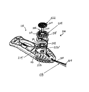
automatically
release the suture from the handle.
SUMMARY OF THE INVENTION
[0005] Embodiments of the present invention are directed to a suture
anchor driver.
According to one aspect, the suture anchor driver has a handle with a proximal
end and a
distal end. The handle has a recess with a shaft extending centrally
therefrom. The suture
anchor driver has a detent ring and a spool. The detent ring has a central
aperture and one or
more projections. The spool has a central aperture and is rotatable between a
first
configuration and a second configuration. The spool has a first side and a
second side. The
second side has a plurality of protrusions extending therefrom. The shaft in
the recess extends
through the central apertures in the detent ring and the spool such that the
projections of the
1
Date Recue/Date Received 2023-07-18
detent ring are adjacent the plurality of protrusions extending from the
spool. In the first
configuration, one of the one or more projections extends bctwoen two of the
plurality of
protrusions, in the second configuration, one of the one or more projections
is aligned with one
of the plurality of protrusions. The one or more projections are anus which
extend radially from
the detent ring, The plurality of protrusions extend radially toward the
central aperture of the
spool,
100061 There
is also described a suture anchor driver having a handle with a
proximal end, a distal end, and a locking arm with a pawl extending therefrom.
The handle
has a recess with a barrier member extending thereacross. The recess is
configured to retain a
spool having a first surface and a second surface. The spool has first and
second channels,
which are at least partially separated between the first and second surfaces.
A plurality of
teeth extend radially from the second surface of the spool. The second channel
of the spool
has a recess configured to store needles connected to a length of suture. In a
first
configuration, the pawl of the locking arm extends between two of the
plurality of teeth. In a
second configuration, the locking arm is displaced such that the pawl is above
the plurality of
teeth. The spool is not rotatable in the first configuration and is rotatable
in the second
configuration.
100071 In
accordance with some embodiments described herein, a suture can
release/unwind from a spool (which can spin with respect to a static detent
ring, for example)
in a handle of a suture anchor driver or anchor deployment device, but the
spool needs to
overcome a force imparted by a tensioning mechanism - teeth of a spool
impacting and
deflecting the finger like or other projections on the static detent ring -
prior to being able to
rotate (as an example), and in turn imparts a tensioning force on a suture
(wrapped around the
spool and extending through the slot on the handle) and to an attached anchor
(when anchor
is fixed, at least somewhat, in the bone hole). After the anchor is
set/deployed in a bone hole,
if the anchor is a soft anchor, this force can be tuned, predetermined and/or
configured/utilized to set a soft anchor and/or test the setting/deployment of
a soft anchor.
Further, the force can be used to test the setting/deployment of a hard
anchor. The force used
to overcome the force imparted by the tensioning mechanism, and to rotate the
spool to
deploy/set and/or test is imparted by a user by pulling the handle away from
the bone
hole/deployment site. The force imparted by the tensioning mechanism can be
increased/decreased in a number of ways including by changing the thickness,
density and/or
length of the finger like projections (or of the teeth), for example, as
should be appreciated by
a person of skill in the art in conjunction with a review of this disclosure.
100081 It
should be appreciated that all combinations of the foregoing concepts and
additional concepts discussed in greater detail below (provided such concepts
are not
2
Date Recue/Date Received 2023-07-18
mutually inconsistent) are contemplated as being part of the inventive subject
matter
disclosed herein. In particular, all combinations of claimed subject matter
appearing at the
end of this disclosure are contemplated as being part of the inventive subject
matter disclosed
herein.
[0009] These and other aspects of the invention will be apparent from and
elucidated
with reference to the embodiment(s) described hereinafter.
BRIEF DESCRIPTION OF THE DRAWINGS
[0010] One or more aspects of the present invention are particularly
pointed out and
distinctly claimed as examples in the claims at the conclusion of the
specification. The
foregoing and other objects, features, and advantages of the invention are
apparent from the
following description taken in conjunction with the accompanying drawings in
which:
[0011] FIG. 1 is a partial exploded perspective view schematic
representation of a suture
anchor driver, according to an embodiment;
[0012] FIG. 2 is a partial cutaway bottom view schematic representation
of the suture
anchor driver, according to an embodiment;
[0013] FIG. 3 is a perspective view schematic representation of the
detent ring of the
tensioning mechanism of the suture anchor driver, according to an embodiment;
[0014] FIG. 4 is a cutaway side view schematic representation of the
spool and detent
ring in a first configuration, according to an embodiment;
[0015] FIG. 5 is a cutaway side view schematic representation of the
spool and detent
ring in a second configuration, according to an embodiment;
[0016] FIG. 6 is a perspective view schematic representation of a suture
anchor driver,
according to an alternative embodiment;
[0017] FIG. 7 is a partial exploded perspective view schematic
representation of a suture
anchor driver, according to an alternative embodiment;
[0018] FIG. 8 is a side view schematic representation of the detent ring
and spool of the
anchor driver in a first configuration, according to an alternative
embodiment;
[0019] FIG. 9 is a side view schematic representation of the detent ring
and spool of the
anchor driver in a second configuration, according to an alternative
embodiment;
[0020] FIG. 10 is a partial exploded perspective view of a suture anchor
driver,
according to another alternative embodiment;
3
Date Recue/Date Received 2023-07-18
[0021] FIG. 11 is a side view schematic representations of a suture
anchor driver in a
first configuration, according to yet another alternative embodiment;
[0022] FIG. 12 is a side view schematic representations of a driver of
the suture anchor
driver inserted into a guide, according to yet another alternative embodiment;
[0023] FIG. 13 is a side view schematic representations of the suture
anchor driver in a
second configuration, according to yet another alternative embodiment;
[0024] FIG. 14 is a perspective view schematic representation of the
spool and suture
components of the suture anchor driver, according to yet another alternative
embodiment;
[0025] FIG. 15 is a top view schematic representation of the spool of the
suture anchor
driver, according to yet another alternative embodiment;
[0026] FIG. 16 is a top view schematic representation of the spool with
the suture
components loaded thereon, according to yet another alternative embodiment;
[0027] FIG. 17 is a top view schematic representation of the spool loaded
into the suture
anchor driver, according to yet another alternative embodiment;
DETAILED DESCRIPTION OF THE INVENTION
[0028] Aspects of the present invention and certain features, advantages,
and details
thereof, are explained more fully below with reference to the non-limiting
examples
illustrated in the accompanying drawings. Descriptions of well-known
structures are omitted
so as not to unnecessarily obscure the invention in detail. It should be
understood, however,
that the detailed description and the specific non-limiting examples, while
indicating aspects
of the invention, are given by way of illustration only, and are not by way of
limitation.
Various substitutions, modifications, additions, and/or arrangements, within
the spirit and/or
scope of the underlying inventive concepts will be apparent to those skilled
in the art from
this disclosure.
[0029] Referring now to the figures, wherein like reference numerals
refer to like parts
throughout, FIG. 1 shows a perspective view schematic representation of a
suture anchor
driver 100, according to an embodiment. The suture anchor driver 100 comprises
a handle
102. The handle 102 extends from a proximal end 104 to a distal end 106 along
a central
longitudinal y ¨ y axis. The handle 102 can be any shape, such as cylindrical
or rectangular,
for example. As shown in the depicted embodiment, the handle 102 is
ergonomically
designed such that the handle 102 is configured to fit within the hand of the
user. The handle
102 can be composed of plastic or any other suitable material (as should be
understood by a
person of skill in the art in conjunction with a review of this disclosure).
4
Date Recue/Date Received 2023-07-18
[0030] Turning now to FIG. 2, there is shown a partial cutaway bottom
view schematic
representation of the suture anchor driver 100, according to an embodiment.
The anchor
driver 100 shown in FIG. 1 also comprises a driver 108 extending into the
distal end 106 of
the handle 102. The driver 108 may be composed of metal, such as stainless
steel, or any
other suitable material (as should be understood by a person of skill in the
art in conjunction
with a review of this disclosure). In the depicted embodiment, the driver 108
extends distally
from the distal end 106 along the central longitudinal y ¨ y axis.
[0031] As shown in FIGs. I and 2, the anchor driver 100 further comprises
a tensioning
mechanism 200. The tensioning mechanism 200 comprises a detent ring 202, a
spool 204,
and a shaft 206, as shown in FIG. 1. In the embodiment shown in FIG. 1, the
handle 102
comprises a recess 110 sized and configured to retain the detent ring 202 and
spool 204
axially therein. The shaft 206 is centrally located within the recess 110 and
extends from the
recess 100 to a first side 112 of the handle 102. In the depicted embodiment,
the shaft 206
does not (but can) extend past the first side 112 of the handle 102. Further,
as shown in FIGs.
1 and 2, the shaft 206 has a pronged end 208 such that the detent ring 202 and
spool 204 can
be removably installed around the shaft 206 within the recess 110. The pronged
end 208
maintains the detent ring 202 and spool 204 within the recess 110, but when
the prongs of the
pronged end 208 are moved toward each other, the detent ring 202 and spool 204
can be
removed from the recess 110.
[0032] Still referring to FIG. 2, the detent ring 202 is positioned
within the recess 110
around the shaft 206. The spool 204 is then positioned within the recess 110
around the shaft
206 and on the detent ring 202 such that the spool 204 extends to the first
side 112 of the
handle 102. Prior to inserting the spool 204 into the recess 110, suture 300
(connected to a
suture anchor (not shown)) is wrapped around the spool 204. The suture anchor
(not shown)
may be any anchor, such as an all-suture or "soft" anchor shown and described
in U.S. Patent
No. 9,826,971.
100331 As a brief background, suture anchors, as the term is used herein,
can include soft
suture anchors and rigid suture anchors. Soft suture anchors are formed from
filaments of
suture material which are retained within pre-formed bone holes by being
deformable to
increase their diameter to a size greater than that of the bone hole, to
thereby reside within the
cancellous bone and under the bone cortex. One such suture anchor is disclosed
in U.S.
Patent No. 9826971. Since soft anchors are commonly made entirely of suture
materials, they
are sometimes called "all-suture" anchors, and generally include a fibrous
construct anchor
Date Recue/Date Received 2023-07-18
body portion (or fibrous, braided or woven fabric-type structure such as a
flexible web, as
described in U.S. Pat. No. 9173652)
and a suture or filament portion. Methods and devices for
inserting/deploying such all-suture anchors are known, examples of which are
disclosed in
U.S. Pat. No. 9173652.
[0034] As described in U.S. Pat. No. 8409252, for example,
"non-soft," "hard" or "rigid" suture
anchors generally include a "hard" anchor body portion (that may or may not
include inner
and outer members) and a suture/filament portion. The anchor body of such
suture anchors
may be formed of a biocompatible and/or bioabsorbable material. These
materials may be of
such composition that they are reabsorbed by the body, e.g., during the
healing process of the
bone. Exemplary materials that are suitable for use in the inner and outer
members include,
but are not limited to, polyetheretherketone ("PEEK"), polylactic acid/beta-
tricalcium
phosphate ("PLA/Beta-TCP") composites, ultra-high molecular weight
polyethylene
("UHMWPE"), as well as other metallic, non-metallic, and polymeric materials.
[0035] As shown in FIG. 2, a first end 302 of the suture 300 can be
pulled through an
aperture 210 within the spool 204 to prevent the suture 300 from unraveling as
it is wound
around the spool 204. In another embodiment, the spool 204 can have any
conventional slot,
hook, or connector to secure the first end 302 of the suture 300. The suture
300 extends from
the spool 204 such that a second end 304 of the suture 300 extends distally
from the handle
102 near the driver 108, as shown in FIG. 2. In an embodiment shown in FIG.
10, the handle
102 comprises a slot 114 or other aperture extending from the recess 110 to a
location on the
handle 102 adjacent the driver 102.
[0036] Referring now to FIG. 3, there is shown a perspective view
schematic
representation of the detent ring 202 of the tensioning mechanism 200 of the
suture anchor
driver 100, according to an embodiment. In the depicted embodiment, the detent
ring 202
comprises a central aperture 212 to accommodate the shaft 206 of the
tensioning mechanism
200 when the detent ring 202 is placed within the recess 110 of the handle
102. The detent
ring 202 also comprises one or more finger-like projections 214 extending from
a surface 216
of the detent ring 202. The finger-like projections 214 engage the spool 204
as described
below.
[0037] Turning back to FIGs. 1-2, the spool 204 similarly comprises a
central aperture
213 for accommodating the shaft 206 within the recess 110 of the handle 102.
The spool 204
also comprises a plurality of ridges, teeth, or other protrusions 218
extending therefrom. The
6
Date Recue/Date Received 2023-07-18
teeth 218 extend from the spool 204 toward the surface 216 of the detent ring
202. When the
detent ring 202 and spool 204 are installed within the recess 110, the finger-
like projections
214 of the detent ring 202 are adjacent the teeth 218 of the spool 204.
[0038] Referring now to FIGs. 4 and 5, there are shown cutaway side views
schematic
representations of the spool 204 and detent ring 202 in a first configuration
and second
configuration, respectively, according to an embodiment. In a first
configuration, a projection
214 of the detent ring 202 is within a gap 220 between two teeth 218 of the
spool 204, as
shown in FIG. 4. To move the tensioning mechanism 200 to a second
configuration, the spool
204 is rotated. The spool 204 is rotated when traction is applied to the
suture 300. The
traction on the suture 300 imparts torque on the spool 204 causing it to
rotate.
[0039] The spool 204 resists rotation because the projections 214 of the
detent ring 202
extending in the gap 220 between the teeth 218 of the spool 204 or catch on
the teeth 218 of
the spool 204. The resistance to the rotation applies force to the anchor (not
shown) attached
to the suture 300. The force causes a deployable suture anchor (not shown) to
expand or
otherwise form toward its final shape. Force is applied to the suture anchor
(not shown) until
the projection 214 of the detent ring 202 overcomes the resistance or traction
and is moved
from the gap 220 between the teeth 218 into alignment with one of the
plurality of the teeth
218, as shown in FIG. 5. Additional tension on the suture 300 causes the
projection 214 of the
detent ring 202 to move into an adjacent gap 220 where the spool 204 against
resists rotation.
As described above, the resistance applies force to the suture anchor (not
shown) causing it to
deploy or form to its final shape. Thus, tension can be selectively applied to
the suture anchor
(not shown) through a selected number of rotations of the spool 204.
[0040] Turning now to FIGs. 6 and 7, there are shown perspective and
partial exploded
perspective views schematic representations of a suture anchor driver 100,
according to an
alternative embodiment. In the depicted embodiment, the detent ring 202 of
tensioning
mechanism 200 of the anchor driver 100 comprises one or more arms 214' instead
of the
projections 214 shown in the embodiment of FIGs, 1-2. In FIG, 7, the arms 214'
extend from
radially, whereas in FIGs. 1-2, the projections 214 extend up from the surface
216 of the
detent ring 202 toward the first side 112 of the handle 102. To accommodate
the radial arms
214', the embodiment of the spool 204 in FIGs. 6-7 comprises radial ridges,
teeth, or other
protrusions 218' which extend inward toward the central aperture 213 in the
spool 204.
[0041] Referring now to FIGs. 8 and 9, there are shown side views
schematic
representations of the detent ring 202 and spool 204 of the anchor driver 100
in a first
configuration and a second configuration, respectively, according to an
alternative
7
Date Recue/Date Received 2023-07-18
embodiment (which can apply to and substantially illustrate a portion of the
alternative
embodiment shown and described with respect to FIGS. 6-7 and FIG. 10). In a
first
configuration, an arm 214' of the detent ring 202 is within a gap 220' between
the teeth 218'
of the spool 204, as shown in FIG. 8. To move the tensioning mechanism 200 to
a second
configuration, the spool 204 is rotated by traction applied to the suture 300.
As described
above, the spool 204 resists rotation, applying force to the suture anchor
(not shown) and
partially deploying it. The spool 204 resists rotation until the arm 214' of
the detent ring 202
is finally moved from the gap 220' between the teeth 218' into alignment with
a tooth 218',
as shown in FIG. 9. As described above, each continued rotation of the spool
204 applies
additional force to the suture 300 and the suture anchor (not shown),
deploying the suture
anchor (not shown).
[0042] Turning now to FIG. 10, there is shown a partial exploded
perspective view
schematic representation of a suture anchor driver 100, according to another
alternative
embodiment. Like the embodiment shown in FIGs. 6-9, the anchor driver 100 in
FIG. 10 has
a detent ring 202 with arms 214' extending radially therefrom. The radial arms
214' engage
radial ridges, teeth, or other protrusions 218' of the spool 204, as shown in
FIG. 10. However,
in the embodiment shown in FIG. 10, the shaft 206' of the tensioning mechanism
200 does
not have a pronged end 208 (as shown in FIG. 1). In the depicted embodiment,
the shaft 206'
is a rigid tube, cylindrical in shape. To maintain the detent ring 202 and the
spool 204 within
the recess 110 of the handle 102, the tensioning mechanism 200 additionally
comprises a
fastener 222. In the depicted embodiment, the fastener 222 is a cap 224 with a
stem 226
extending centrally therefrom. In use, the stem 226 of the fastener 222 is
placed through the
apertures 213, 212 in the spool 204 and the detent ring 202, and through an
inner channel 228
within the tubular shaft 206'.
[0043] Referring now to FIGs. 11-13, there are shown side views schematic
representations of a suture anchor driver 400 between first and second
configurations,
according to yet another alternative embodiment. In the embodiment shown in
FIGs. 11-13,
the anchor driver 400 comprises a handle 402 extending from a proximal end 404
to a distal
end 406 along a central longitudinal y ¨ y axis. The handle 402 can be any
shape, composed
of plastic or any other suitable material, and ergonomically designed to fit
within the hand of
the user (as described above in conjunction with the embodiments shown in
FIGs. 1-10). The
anchor driver 400 shown in FIG. 11 also comprises a driver 408 extending into
the distal end
406 of the handle 402. The driver 408 may be composed of metal (or any other
suitable
material) and extends distally from the distal end 406 along the central
longitudinal y ¨ y
8
Date Recue/Date Received 2023-07-18
axis. As shown in FIG. 11, the handle 402 comprises a recess 410 to receive a
spool 504 of a
tensioning mechanism 500. In the depicted embodiment, the spool 504 slides
into the recess
410 and is held within the recess 410 by a barrier member 502 of the
tensioning mechanism
500, such as an arm or rod of the handle 402.
[0044] Turning briefly to FIGs. 14-17, there are shown various views of a
spool 504 and
suture components 600, according to yet another alternative embodiment. FIG.
14 shows a
perspective view of the spool 504 and suture components 600 of the suture
anchor driver 400.
The suture components 600 include a foam block 602 with needles 604 embedded
or
otherwise hooked therein and a length of suture 606 attached to the needles
604. The suture
components 600 also include a suture anchor 306 on a length of suture 300. In
the depicted
embodiment, the needles 604 are curved or hooked.
[0045] FIG. 15 shows an embodiment of the spool 504 with a first surface
506 and a
second surface 508 with at least partially separated first and second channels
510, 512
therebetween. As shown in both FIGs. 15 and 16 (and FIG. 11), the second
surface 508 of the
spool 504 comprises a plurality of radially extending teeth 514. The second
channel 512 of
the spool 504 comprises a recess 516 configured to accommodate or otherwise
house the
foam block 602, as shown in FIG. 16.
[0046] As the needles 604 are curved or hooked, the needles 604 extend
along the
second channel 512 when the foam block 602 is inserted into the recess 516 of
the spool 504.
As shown in FIG. 17, the length of suture 606 attached to the needles 604 is
wrapped around
the first channel 510. After the length of suture 606 attached to the needles
604 is loaded on
the spool 504, the spool 504 is placed within the recess 410 of the handle
402. As shown in
FIG. 11, the spool 504 is placed within the recess 410 such that the second
surface 508 and
teeth 514 are adjacent the barrier member 502 of the handle 402. The suture
anchor 306 (and
attached suture 300) is also loaded on the driver 408.
[0047] Still referring to FIG. 11, the handle 402 additionally comprises
a locking arm
416 with a pawl 412 or other similar protrusion extending into a gap 518
between the two of
the plurality of teeth 514 of the spool 504 when the anchor driver 400 is in
the first
configuration. In the first configuration, the pawl 412 prevents the spool 504
from rotating
within the recess 410 of the handle 402 so that the suture anchor 306 can be
inserted with the
suture 300 having a fixed tension. Specifically, the suture anchor 306 is
inserted into a pre-
formed hole (or bone hole) with tension on the suture 300, which is connected
to the spool
504 in the handle 402. As the spool 504 cannot rotate, no slack (or reduction
in tension) can
9
Date Recue/Date Received 2023-07-18
be introduced to the suture 300. With fixed tension on the suture anchor 306,
it is inserted
into the bone hole by the driver 408 through a guide 700, as shown in FIG. 12.
[0048] Turning now to FIG. 13, there is shown a side view of the suture
anchor driver
400 in the second configuration, according to yet another alternative
embodiment. In the
depicted embodiment, the driver 408 has been advanced as far as possible
within the guide
700. The guide 700 comprises a feature 702 which enters a slot 414 within the
handle 402
adjacent the locking arm 416 having the pawl 412. As the driver 408 extends as
far as
possible into the guide 700, the feature 702 of the guide 700 enters the slot
414 and deflects
the locking arm 416 away from the spool 504. As the locking arm 416 is
deflected away from
the spool 504, the pawl 412 disengages the gap 518 between the teeth 514 of
the spool 504.
The spool 504 is then free to spin or otherwise rotate within the recess 410
of the handle 402.
As the spool 504 can spin within the recess 410, the needles 604 and the
attached length of
suture 606, and the suture 300 (connected to the suture anchor 306) can be
unspooled (i.e.,
removed) from the handle 402 to complete installation of the suture anchor
306.
[0049] [INTENTIONALLY LEFT BLANK]
[0050] While various embodiments have been described and illustrated
herein, those of
ordinary skill in the art will readily envision a variety of other means
and/or structures for
performing the function and/or obtaining the results and/or one or more of the
advantages
described herein, and each of such variations and/or modifications is deemed
to be within the
scope of the embodiments described herein. More generally, those skilled in
the art will
readily appreciate that all parameters, dimensions, materials, and
configurations described
herein are meant to be exemplary and that the actual parameters, dimensions,
materials,
and/or configurations will depend upon the specific application or
applications for which the
teachings is/are used. Those skilled in the art will recognize, or be able to
ascertain using no
more than routine experimentation, many equivalents to the specific
embodiments described
herein. It is, therefore, to be understood that the foregoing embodiments are
presented by
way of example only and that, within the scope of the appended claims and
equivalents
thereto, embodiments may be practiced otherwise than as specifically described
and claimed.
Embodiments of the present disclosure are directed to each individual feature,
system, article,
material, kit, and/or method described herein. In addition, any combination of
two or more
such features, systems, articles, materials, kits, and/or methods, if such
features, systems,
Date Recue/Date Received 2023-07-18
articles, materials, kits, and/or methods are not mutually inconsistent, is
included within the
scope of the present disclosure.
[0051] The terminology used herein is for the purpose of describing
particular
embodiments only and is not intended to be limiting of the invention. As used
herein, the
singular forms "a", "an" and "the" are intended to include the plural forms as
well, unless the
context clearly indicates otherwise. It will be further understood that the
terms "comprise"
(and any form of comprise, such as "comprises" and "comprising"), "have" (and
any form of
have, such as, "has" and "having"), "include" (and any form of include, such
as "includes"
and "including"), and "contain" (any form of contain, such as "contains" and
"containing")
are open-ended linking verbs. As a result, a method or device that
"comprises", "has",
"includes" or "contains" one or more steps or elements. Likewise, a step of
method or an
element of a device that "comprises", "has", "includes" or "contains" one or
more features
possesses those one or more features, but is not limited to possessing only
those one or more
features. Furthermore, a device or structure that is configured in a certain
way is configured
in at least that way, but may also be configured in ways that are not listed.
[0052] The corresponding structures, materials, acts and equivalents of
all means or step
plus function elements in the claims below, if any, are intended to include
any structure,
material or act for performing the function in combination with other claimed
elements as
specifically claimed. The description of the present invention has been
presented for
purposes of illustration and description, but is not intended to be exhaustive
or limited to the
invention in the form disclosed. Many modifications and variations will be
apparent to those
of ordinary skill in the art without departing from the scope and spirit of
the invention. The
embodiment was chosen and described in order to best explain the principles of
one or more
aspects of the invention and the practical application, and to enable others
of ordinary skill in
the art to understand one or more aspects of the present invention for various
embodiments
with various modifications as are suited to the particular use contemplated.
11
Date Recue/Date Received 2023-07-18