Note: Descriptions are shown in the official language in which they were submitted.
Utility Patent Application Customer No. 65,770
XConnect, LLC
IGNITER FOR A SETTING TOOL FOR A
PERFORATING GUN ASSEMBLY
STATEMENT OF RELATED APPLICATIONS
100011 The present application claims the benefit of U.S. Serial No.
63/373,727 filed
August 28, 2022. That application was titled "Igniter for Setting Tool for a
Perforating Gun
Assembly."
[0002] The present application also claims the benefit of U.S. Serial No.
63/386,136 filed
December 05, 2022. That application was also titled "Igniter for Setting Tool
for a Perforating
Gun Assembly."
[0003] This application is also filed as a Continuation-in-Part of U.S.
Serial No.
17/547,053 filed December 09, 2021. That application was titled "Bulkhead for
Perforating
Gun Assembly."
[0004] The '053 patent application was filed as a Continuation-in-Part of
U.S. Serial No.
17/175,651 (1312.0007-US3). That application was filed on February 13, 2021,
and is entitled
"Detonation System Having Sealed Explosive Initiation Assembly." The '651
application
issued as U.S. Patent No. 11,293,737 on April 05, 2022.
[0005] The '651 patent application was filed as a Continuation-in-Part of
U.S. Serial No.
16/996,692 (1312.0007-U52). That application was filed on August 18, 2020, and
is also
entitled "Detonation System Having Sealed Explosive Initiation Assembly." The
'692
application issued on August 02, 2022 as U.S. Patent No. 11,402,190.
[0006] Each of these applications is incorporated herein in its entirety by
reference.
STATEMENT REGARDING FEDERALLY SPONSORED RESEARCH OR DEVELOPMENT
[0007] Not applicable.
2
Date Regue/Date Received 2023-07-24
Utility Patent Application Customer No. 65,770
XConnect, LLC
THE NAMES OF THE PARTIES TO A JOINT RESEARCH AGREEMENT
[0008] Not applicable.
BACKGROUND OF THE INVENTION
[0009] This section is intended to introduce various aspects of the art,
which may be
associated with exemplary embodiments of the present disclosure. This
discussion is believed
to assist in providing a framework to facilitate a better understanding of
particular aspects of
the present disclosure. Accordingly, it should be understood that this section
should be read
in this light, and not necessarily as admissions of prior art.
Technical Field of the Invention
[0010] The present disclosure relates to the field of hydrocarbon recovery
operations.
More specifically, the invention relates to a perforating gun assembly used
for the perforation
of steel casing in a wellbore. Further still, the invention relates to an
igniter system used to
activate a setting tool located at a downstream end of the perforating gun
assembly.
Discussion of the Background
[0011] For purposes of this disclosure, U.S. Patent No. 11,402,190 will be
referred to as
"the parent application." The parent application has been incorporated herein
in its entirety by
reference.
[0012] In the drilling of an oil and gas well, a near-vertical wellbore is
formed through the
earth using a drill bit urged downwardly at a lower end of a drill string.
After drilling to a
predetermined depth, the drill string and drill bit are removed and the
wellbore is lined with a
string of steel casing. An annular area is thus formed between the string of
casing and the
formation penetrated by the wellbore.
[0013] A cementing operation is conducted in order to fill or "squeeze" the
annular volume
with cement along part or all of the length of the wellbore. The combination
of cement and
3
Date Regue/Date Received 2023-07-24
Utility Patent Application Customer No. 65,770
XConnect, LLc
casing strengthens the wellbore and facilitates the zonal isolation, and
subsequent completion,
of hydrocarbon-producing pay zones behind the casing.
[0014] In connection with the completion of the wellbore, several strings
of casing having
progressively smaller outer diameters will be cemented into the wellbore.
These will include
a string of surface casing, one or more strings of intermediate casing, and
lastly a string of
production casing. The process of drilling and then cementing progressively
smaller strings of
casing is repeated until the well has reached total depth. In some instances,
the final string of
casing is a liner, that is, a string of casing that is not tied back to the
surface.
[0015] Within the last two decades, advances in drilling technology have
enabled oil and
gas operators to "kick-off" and steer wellbore trajectories from a vertical
orientation to a near-
horizontal orientation. The horizontal "leg" of each of these wellbores now
often exceeds a
length of one mile, and sometimes two or even three miles. This significantly
multiplies the
wellbore exposure to a target hydrocarbon-bearing formation. The horizontal
leg will typically
include the production casing.
[0016] Figure 1 is a side, cross-sectional view of a wellbore 100, in one
embodiment. The
wellbore 100 defines a bore 10 that has been drilled from an earth surface 105
(or simply,
surface) into a subsurface 110. The wellbore 100 is formed using any known
drilling
mechanism, but preferably using a land-based rig or an offshore drilling rig
operating on a
platform.
[0017] The wellbore 100 is completed with a first string of casing 120,
sometimes referred
to as surface casing. The wellbore 100 is further completed with a second
string of casing 130,
typically referred to as an intermediate casing. In deeper wells, that is,
wells completed below
7,500 feet, at least two intermediate strings of casing will be used. In
Figure 1, a second
intermediate string of casing is shown at 140.
[0018] The wellbore 100 is finally completed with a string of production
casing 150. In
the view of Figure 1, the production casing 150 extends from the surface 105
down to a
4
Date Regue/Date Received 2023-07-24
Utility Patent Application Customer No. 65,770
XConnect, LLc
subsurface formation, or "pay zone" 115. The wellbore 100 is completed
horizontally,
meaning that a near-horizontal "leg" 156 is provided within the pay zone 115.
The production
casing 150 extends substantially across the horizontal leg 156.
[0019] It is observed that the annular region around the surface casing 120
is filled with
cement 125. The cement (or cement matrix) 125 serves to isolate the wellbore
100 from fresh
water zones and potentially porous formations around the string of casing 120.
[0020] The annular regions around the intermediate casing strings 130, 140
are also filled
with cement 135, 145. Similarly, the annular region around the production
casing 150 is filled
with cement 155. However, the cement 135, 145, 155 is optionally only placed
behind the
respective casing strings 130, 140, 150 up to the lowest joint of the
immediately surrounding
casing string. Thus, a non-cemented annular area 132 is typically preserved
above the cement
matrix 135, a non-cemented annular area 142 may optionally be preserved above
the cement
matrix 135, and a non-cemented annular area 152 is frequently preserved above
the cement
matrix 155.
[0021] The horizontal leg 156 of the wellbore 100 includes a heel 153,
located at an
inflection point between the near-vertical leg and near-horizontal leg of the
wellbore 100, and
a toe 154. In this instance, the toe 154 defines the end (or "TD") of the
wellbore 100. In order
to enhance the recovery of hydrocarbons, particularly in low-permeability
formations, the
casing 150 along the horizontal section 156 undergoes a process of perforating
and fracturing
(or in some cases perforating and acidizing). Due to the exceptionally long
lengths of new
horizontal wells, the perforating and formation treatment process is typically
carried out in
stages.
[0022] In one method, a perforating gun assembly 200 is pumped down the
horizontal leg
156 at the end of a wireline 240. The perforating gun assembly 200 will
include a series of
perforating guns (shown at 210 in Figure 2), with each gun having sets of
charges ready for
detonation. The charges associated with one of the perforating guns 210 are
detonated and
perforations (not shown) are "shot" into the casing 150. Those of ordinary
skill in the art will
Date Regue/Date Received 2023-07-24
Utility Patent Application Customer No. 65,770
XConnect, LLc
understand that a perforating gun 210 has explosive charges, typically shaped,
hollow or
projectile charges, which are ignited to create holes in the casing 150 (and,
if present, the
surrounding cement) and pass at least a few inches and possibly several feet
into the subsurface
formation 115. The perforations create fluid communication with the
surrounding formation
115 (or pay zone) so that hydrocarbon fluids can flow into the casing 150.
[0023] After perforating, the operator will fracture (or otherwise
stimulate) the formation
115 through the perforations (not shown). This is done by pumping treatment
fluids into the
formation 115 at a pressure above a formation parting pressure. After the
fracturing operation
is complete, the wireline 240 will be raised from the surface and the
perforating gun assembly
200 will be positioned at a new location (or "depth") along the horizontal
wellbore 156. A
plug (such as plug 112) is set below the perforating gun assembly 200 using a
setting tool 160,
and new shots are fired in order to create a new set of perforations.
Thereafter, treatment fluid
is again pumping into the wellbore 100 and into the formation 115. In this
way, a second set
(or "cluster") of fractures is formed away from the horizontal leg 156 of the
wellbore 100.
[0024] The process of setting a plug, perforating the casing, and
fracturing the formation
is repeated in multiple stages until the wellbore 100 has been completed, that
is, the wellbore
100 is ready for production. In Figure 1, it can be seen that two separate
plugs 112 have been
placed along the horizontal leg 156 of the wellbore 100. Of course, it is
understood that the
horizontal leg 156 of the completed wellbore 100 may extend many hundreds or
even
thousands of feet, with multiple plugs 112 being set between the stages. A
string of production
tubing (not shown) is then placed in the wellbore 100 to provide a conduit for
production fluids
to flow up to the surface 105.
[0025] In order to provide perforations for the multiple stages without
having to pull the
perforating gun assembly 200 after every detonation, the perforating gun
assembly 200
employs multiple guns 210 in series. Figure 2 is a side view of an
illustrative perforating gun
assembly 200, or at least a portion of an assembly. The perforating gun
assembly 200
comprises a string of individual perforating guns 210.
6
Date Regue/Date Received 2023-07-24
Utility Patent Application Customer No. 65,770
XConnect, LLC
[0026] Each perforating gun 210 represents various components. These
typically include
a "gun bane!" 212 which serves as an outer tubular housing. An uppermost gun
barrel (or gun
barrel housing 212) is supported by an electric wire (or "e-line") 240 that
extends from the
surface 105 and delivers electrical energy down to the perforating gun
assembly 200. Each
perforating gun 210 also includes an explosive initiator, or "detonator"
(shown in phantom at
229). The detonator 229 is typically a small aluminum housing having an
internal resistor.
The detonator 229 receives electrical energy from the surface 105 and through
the e-line 240,
which heats the resistor.
[0027] The detonator 229 is surrounded by a sensitive explosive material
such as RDX (or
hexogen). When an electrical current is run through the detonator 229, a small
explosion is set
off by the electrically heated resistor. Stated another way, the explosive
material is ignited by
the detonator 229. This small explosion sets off an adjacent detonating cord
(not shown).
When ignited, the detonating cord initiates one or more shots, typically
referred to as "shaped
charges." The shaped charges (shown at 520 in Figure 5 of the parent
application) are held in
an inner tube (shown at 500 in Figure 5 of the parent application), referred
to as a carrier tube,
for security and discharge through openings 215 in the selected gun bane! 212.
As the RDX
is ignited, the detonating cord propagates an explosion down its length to
each of the shaped
charges along the carrier tube.
[0028] The perforating gun assembly 200 may include short centralizer subs
220. The
perforating gun assembly 200 also includes the inner tubes, which reside
within the gun barrel
housings 212 and are not visible in Figure 2. In addition, tandem subs 225 are
used to connect
the gun bane! housings 212 end-to-end. Each tandem sub 225 comprises a metal
threaded
connector placed between the perforating guns 210. (A complete tandem sub is
shown at 400
in Figure 4 of the parent application.) Typically, the gun bane! housings 212
will have female-
by-female threaded ends while the tandem subs 225 have opposing male threaded
ends
(indicated at 404 of the parent application).
[0029] The perforating gun assembly 200 with its long string of gun barrels
(the housings
212 of the perforating guns 210 and the carrier tubes) is carefully assembled
at the surface 105,
7
Date Regue/Date Received 2023-07-24
Utility Patent Application Customer No. 65,770
XConnect, LLc
and then lowered into the wellbore 10 at the end of the e-line 240. The e-line
240 extends
upward to a control interface (not shown) located at the surface 105. An
insulated connection
member 230 connects the e-line 240 to the uppermost perforating gun 210. Once
the
perforating gun assembly 200 is in place within the wellbore 100, the operator
of the control
interface sends electrical signals to the perforating gun assembly 200 for
detonating the shaped
charges (shown at 520 of the parent application) and for creating perforations
into the casing
150.
[0030] As noted in Figures 1 and 2, a setting tool 160 resides at the end
of the perforating
gun assembly 200. The setting tool 160 may be connected to the lowermost
perforating gun
210 by means of a tandem sub 225 and an adapter 162. The setting tool 160 is
used to set the
plug 112 along the wellbore 100 at a desired depth. This is typically done by
using an igniter
which initiates the burning of an explosive component.
[0031] After the casing 150 has been perforated and at least one plug 112
has been set, the
setting tool 160 and the perforating gun assembly 200 are removed from the
wellbore 100 and
a ball (not shown) is dropped into the wellbore 100 to close the plug 112.
When the plug 112
is closed, a fluid (e.g., water, water and sand, fracturing fluid, etc.) is
pumped by a pumping
system down the wellbore 100 (typically through coiled tubing) for fracturing
purposes. For a
formation fracturing operation, the pumping system will create downhole
pressure that is above
the formation parting pressure.
[0032] As noted, the above operations may be repeated multiple times for
perforating
and/or fracturing the casing 150 at multiple locations, corresponding to
different stages of the
wellbore 100. Multiple plugs 112 may be used for isolating the respective
stages from each
other during the fracturing phases. When the fracturing of the casing 150 is
completed for all
stages, the plugs 112 are drilled out and the wellbore 100 is cleaned using a
circulating tool.
[0033] It can be appreciated that a reliable actuation signal must be
provided to the igniter
to initiate the burning of the power charge housed within the setting tool
160. This causes a
chemical reaction that strokes the setting tool 160 and sets the plug 112.
However, a need
8
Date Regue/Date Received 2023-07-24
Utility Patent Application Customer No. 65,770
XConnect, LLc
exists for a bulkhead that resides within the tandem sub 225 below the
lowermost gun barrel
housing 212 that reliably transmits an actuation signal to an igniter. This
actuation signal is
sent before charges in the lowermost gun barrel housing are detonated.
SUMMARY OF THE INVENTION
[0034] An initiator system for a setting tool is provided. The initiator
system is designed
for use with a perforating gun assembly for perforating a wellbore.
Specifically, the initiator
system is used to actuate a setting tool for a plug or a packer in a wellbore.
In one aspect, the
plug is a so-called frac plug that resides at the end of, or below, the
perforating gun assembly.
[0035] The initiator system first includes a firing head. The firing head
comprises a tubular
body having a first end, and a second end opposite the first end. The tubular
body defines a
bore extending from the first end to the second end, with the bore having an
upstream chamber
and a downstream chamber. Preferably, the firing head is fabricated from
steel.
[0036] The initiator system also comprises a bulkhead. The bulkhead resides
within the
bore of the firing head. The bulkhead has a first end, a second end, and a
receptacle extending
between the first and second ends. The bulkhead comprises a tubular body
fabricated from a
non-conductive material such as plastic (a polycarbonate) or nylon.
[0037] The initiator system further includes a signal pin. The signal pin
has an elongated
shaft residing within the receptacle of the tubular bulkhead. The signal pin
extends from the
second end of the tubular bulkhead, and is fabricated from an electrically
conductive material
for transmitting actuation signals. Preferably, the signal pin is fabricated
from brass.
[0038] The initiator system also comprises an ignition tube. The ignition
tube comprises
a cylindrical body having an upstream end and a downstream end. The ignition
tube forms an
ignition chamber between the upstream and downstream ends of the ignition
tube. Of interest,
the upstream end of the ignition tube receives the second end of the tubular
bulkhead within
the downstream end of the bore of the firing head.
9
Date Regue/Date Received 2023-07-24
Utility Patent Application Customer No. 65,770
XConnect, LLC
[0039] As the name implies, the initiator system further includes an
ignitor. The ignitor
resides within the ignition chamber, with the ignitor being in electrical
communication with
the second end of the signal pin. The ignitor may be in electrical
communication with the
second end of the signal pin by means of an electric wire.
[0040] The initiator system may also comprise:
an addressable switch; and
a switch housing holding the addressable switch, with the switch housing
residing within the upstream chamber of the bore of the firing head.
[0041] The initiator system also has an explosive component. In this
respect, the igniter
houses a small explosive load. The explosive component resides within the
ignition chamber.
The explosive component is configured to initiate when the signal pin
transmits the electrical
actuation signal to the igniter. The explosive component may then, in turn,
initiate a power
charge positioned within the setting tool.
[0042] In a preferred arrangement, the first end of the tubular body of the
firing head is
threadedly connected to a gun barrel housing of a perforating gun. The gun
barrel housing
comprises an electric line ( or "e-line") that transmits signals. The
addressable switch is in
electrical communication with the electric line and is configured to receive
(i) detonation
signals for perforating gun charges in the gun barrel housing. It is
understood that this signal
would only be sent after a separate signal was sent to the igniter, causing
the setting tool to set
the fracturing plug. Thus, the electric line is also configured to (ii)
transmit the actuation signal
to the signal pin and on to the igniter.
[0043] Also in a preferred arrangement, the elongated shaft of the signal
pin also extends
from the first end of the tubular bulkhead. A banana clip may be placed over
the first end of
the signal pin. The banana clip extends at least partially into the switch
housing and places the
addressable switch in electrical communication with the signal pin.
Date Regue/Date Received 2023-07-24
Utility Patent Application Customer No. 65,770
XConnect, LLC
[0044] A method of actuating a setting tool in a wellbore is also provided
herein. In one
aspect, the method first comprises providing a firing head. The firing head
may be in
accordance with the firing head described above in its various arrangements.
In one
embodiment, the firing head comprises:
a tubular body having a first end, and a second end opposite the first end;
a bore extending from the first end to the second end, wherein the bore of the
firing head has an upstream chamber and a downstream chamber;
a tubular bulkhead residing in the bore of the firing head, with the tubular
bulkhead having a first end, a second end, and a receptacle extending between
the first
end and the second end;
a signal pin having an elongated shaft residing within the receptacle of the
tubular bulkhead and extending out from the second end of the tubular
bulkhead,
wherein the signal pin is fabricated from an electrically conductive material
for
transmitting an actuation signal;
a cylindrical ignition tube having an upstream end and a downstream end
forming an ignition chamber there between, wherein the upstream end of the
ignition
tube receives the second end of the tubular bulkhead within the downstream
chamber
of the bore of the firing head;
an ignitor residing within the ignition chamber, with the ignitor being in
electrical communication with the second end of the signal pin; and
an explosive component also residing within the ignition chamber.
[0045] The method also includes placing an addressable switch in the
upstream chamber.
[0046] The method further comprises mechanically attaching the firing head
to a
lowermost perforating gun along a perforating gun assembly, wherein the
perforating gun
assembly receives an electric line.
11
Date Regue/Date Received 2023-07-24
Utility Patent Application Customer No. 65,770
XConnect, LLC
[0047] Additionally, the method includes electrically connecting an
upstream end of the
signal pin to the electric line, and electrically connecting a downstream end
of the signal pin
to the igniter.
[0048] The method also comprises mechanically attaching a setting tool for
setting a
fracturing plug to a lowermost end of the firing head. The method then
includes sending an
actuation signal from a surface of the wellbore, through the electric line, to
the signal pin in
the bulkhead, and to the ignitor, and thereby initiating the explosive
component. This, in turn,
ignites a power charge in the setting tool, causing the fracturing plug to be
set in the wellbore.
[0049] In one aspect, an upstream end of the signal pin extends out from
the first (or
upstream )end of the bulkhead, while a downstream end of the signal pin
extends out from the
second (or downstream) end of the bulkhead. In this instance, a banana clip
may be placed
over the first end of the signal pin. The electric line is in electrical
communication with the
banana clip, and the banana clip extends at least partially into the switch
housing and places
the addressable switch in electrical communication with the signal pin. Thus,
a solderless
connection is provided.
[0050] In another aspect, an upstream end of the signal pin resides
entirely within the
receptacle of the tubular bulkhead. Here. the signal pin receives the
actuation signal from a
pre-wired bullet terminal inserted into the first end of the tubular bulkhead.
This again
produces a solderless connection. Alternatively, the actuation signal is
received from a
conductive post threaded into an upstream end of the tubular bulkhead. The
electric line is in
electrical communication with the pre-wired bullet terminal (or the threaded
conductive post).
[0051] In either aspect, a ground wire may be connected to the igniter. The
cylindrical
ignition tube is crimped onto the second end of the tubular bulkhead, and the
ground wire is
wrapped around the second end of the tubular bulkhead beneath the cylindrical
ignition tube.
This provides a solderless crimp connection for the ground wire.
12
Date Regue/Date Received 2023-07-24
Utility Patent Application Customer No. 65,770
XConnect, LLC
[0052] In one arrangement, the explosive component ignites in response to
resistive heat
generated when the signal pin transmits the actuation signal to the igniter.
[0053] In one aspect, the method may also include removing the perforating
gun assembly
and the firing head from the wellbore.
Brief Description of the Drawings
[0054] So that the manner in which the present inventions can be better
understood, certain
illustrations, charts and/or flow charts are appended hereto. It is to be
noted, however, that the
drawings illustrate only selected embodiments of the inventions and are
therefore not to be
considered limiting of scope, for the disclosures herein may admit to other
equally effective
embodiments and applications.
[0055] Figure 1 is a cross-sectional side view of a wellbore. The wellbore
is being completed
with a horizontal leg. A perforating gun assembly is shown having been pumped
into the
horizontal leg at the end of an e-line.
[0056] Figure 2 is a side view of a perforating gun assembly. The
perforating gun assembly
represents a series of perforating guns having been threadedly connected end-
to-end. Tandem subs
are shown between gun barrels of the perforating guns, providing the threaded
connections. A
plug is provided at a downstream end of the perforating gun assembly.
[0057] Figure 3A is a side view of a novel tandem sub for connecting a
perforating gun to a
setting tool in a wellbore. The tandem sub may be referred to in this context
as a firing head.
[0058] Figure 3B is a perspective view of the firing head of Figure 3A.
[0059] Figure 3C is a cross-sectional view of the firing head of Figure 3A.
[0060] Figure 4A is another cross-sectional view of the firing head of
Figure 3A. Here, a
switch housing and an initiator assembly have been placed within a bore of the
firing head.
13
Date Regue/Date Received 2023-07-24
Utility Patent Application Customer No. 65,770
XConnect, LLC
[0061] Figure 4B is a perspective view of the switch housing that resides
within the firing
head of Figure 4A.
[0062] Figure 4C is a perspective view of the addressable switch that
resides within the
switch housing of Figure 4B.
[0063] Figure 5A is a side view of a bulkhead used in the initiator
assembly of the present
invention, in one embodiment. An upstream end of the bulkhead includes a
banana clip used
as an electrical connector.
[0064] Figure 5B is a first perspective view of the bulkhead of Figure 5A.
Here, the
bulkhead is seen from a downstream end.
[0065] Figure 5C is a second perspective view of the bulkhead of Figure 5A.
Here, the
bulkhead is seen from an upstream end.
[0066] Figure 6A is another side view of the bulkhead of Figure 5A. Here,
the bulkhead
is in electrical communication with an igniter.
[0067] Figure 6B is a perspective view of the bulkhead and igniter of
Figure 6A. The
igniter resides within an ignition tube. The ignition tube is shown in
phantom.
[0068] Figure 7A is a side view of a bulkhead as may be used in the
initiator assembly of
the present invention, in a second embodiment. An upstream end of the bulkhead
is left blank.
[0069] Figure 7B is a first perspective view of the bulkhead of Figure 7A.
The bulkhead
is seen from the upstream end. A threaded bore is shown within the bulkhead.
[0070] Figure 7C is a second perspective view of the bulkhead of Figure 7A.
Here, the
bulkhead is seen from a downstream end.
[0071] Figure 8 is another side view of the bulkhead of Figure 7A. Here,
the bulkhead is
in electrical communication with an igniter. The isolation tube is shown in
cross-section.
14
Date Regue/Date Received 2023-07-24
Utility Patent Application Customer No. 65,770
XConnect, LLC
[0072] Figures 9A and 9B together present a flow chart showing steps for a
method of
setting a tool in a wellbore, in one embodiment.
Definitions
[0073] For purposes of the present application, it will be understood that
the term
"hydrocarbon" refers to an organic compound that includes primarily, if not
exclusively, the
elements hydrogen and carbon. Hydrocarbons may also include other elements,
such as, but
not limited to, halogens, metallic elements, nitrogen, carbon dioxide, and/or
sulfuric
components such as hydrogen sulfide.
[0074] As used herein, the terms "produced fluids," "reservoir fluids" and
"production
fluids" refer to liquids and/or gases removed from a subsurface formation,
including, for
example, an organic-rich rock formation. Produced fluids may include both
hydrocarbon
fluids and non-hydrocarbon fluids. Production fluids may include, but are not
limited to, oil,
natural gas, pyrolyzed shale oil, synthesis gas, a pyrolysis product of coal,
nitrogen, carbon
dioxide, hydrogen sulfide and water.
[0075] As used herein, the term "fluid" refers to gases, liquids, and
combinations of gases
and liquids, as well as to combinations of gases and solids, combinations of
liquids and solids,
and combinations of gases, liquids, and solids.
[0076] As used herein, the term "surface" refers to a location on the
earth's surface. The
surface may be a land surface or a water surface.
[0077] As used herein, the term "subsurface" refers to geologic strata
occurring below the
earth's surface.
[0078] As used herein, the term "formation" refers to any definable
subsurface region
regardless of size. The formation may contain one or more hydrocarbon-
containing layers,
one or more non-hydrocarbon containing layers, an overburden, and/or an
underburden of any
geologic formation. A formation can refer to a single set of related geologic
strata of a specific
Date Regue/Date Received 2023-07-24
Utility Patent Application Customer No. 65,770
XConnect, LLc
rock type, or to a set of geologic strata of different rock types that
contribute to or are
encountered in, for example, (i) the creation, generation and/or entrapment of
hydrocarbons or
minerals, and (ii) the execution of processes used to extract hydrocarbons or
minerals from the
subsurface region.
[0079] As used herein, the term "wellbore" refers to a hole in the
subsurface made by
drilling or insertion of a conduit into the subsurface. A wellbore may have a
substantially
circular cross section, or other cross-sectional shapes. The term "well," when
referring to an
opening in the formation, may be used interchangeably with the term
"wellbore."
[0080] Reference herein to "one embodiment" or "an embodiment" means that a
particular
feature, structure, or characteristic described in connection with an
embodiment is included in
at least one embodiment of the subject matter disclosed. Thus, the appearance
of the phrases
"in one embodiment" or "in an embodiment" in various places throughout the
specification is
not necessarily referring to the same embodiment.
Detailed Description of Certain Embodiments
[0081] The following description of the embodiments refers to the
accompanying
drawings. The same reference numbers in different drawings identify the same
or similar
elements. The following detailed description does not limit the invention;
instead, the scope
of the inventions is defined by the appended claims.
[0082] In the following, the terms "upstream" and "downstream" are being
used to indicate
that one gun barrel of a perforating gun may be situated above and one below
another gun
barrel, respectively. However, one skilled in the art would understand that
the present
disclosure is not limited only to the upstream gun or only to the downstream
gun, but in fact
can be applied to either gun. In other words, the terms "upstream" and
"downstream" are not
necessarily used in a restrictive manner, but only to indicate, in a specific
embodiment, the
relative positions of perforating guns or other components.
16
Date Regue/Date Received 2023-07-24
Utility Patent Application Customer No. 65,770
XConnect, LLC
100831 Figure 3A is a side view of a tandem sub 300 for connecting a
perforating gun
(such as perforating gun 200 shown in Figure 2) to a setting tool 160 (as
shown in Figure 2)
in a wellbore 100. Figure 3B is a perspective view of the tandem sub 300 of
Figure 3A. The
tandem sub 300 will be referred to in this context as a firing head. The
firing head 300 will be
described in connection with Figures 3A and 3B together.
[0084] The firing head 300 comprises a body 310. The body 310 has a first
end 312 and a
second end 314 opposite the first end 312. The first end 312 resides in an
upstream position
within a wellbore (such as wellbore 100), while the second end 314 resides in
a downstream
position within the wellbore 100.
[0085] The body 310 has an inner bore 305 which extends from the first end
312 to the
second end 314. The body 310 is dimensioned to contain components of an
initiator assembly
(shown at 600 in Figure 6A and discussed below). The body 310 includes threads
322
proximate the upstream end 312 of the body 310. The threads 322 are used to
connect to a
downstream end of a perforating gun 210, particularly, to a gun barrel housing
212 (as shown
in Figure 2) of a lowermost perforating gun 210 in a perforating gun assembly
200. Preferably,
threads 322 are male threads. At the same time, threads 324 connect to the
upstream end of a
setting tool adapter (shown at 162 in Figure 2). Preferably, threads 324 are
also male threads.
[0086] The body 310 of the firing head 300 includes a shoulder 330. The
shoulder 330
comprises an upstream side 332 and a downstream side 334. The upstream side
332 serves as a
stop member that prevents over-threading of the gun barrel housing 212, while
the downstream
side 334 serves as a stop member that prevents over-threading of the setting
tool adapter 162.
100871 Figure 3C is a cross-sectional view of the firing head 300 of Figure
3A. In this
view, the bore 305 is more clearly seen. The bore 305 comprises an upstream
chamber 302
and a downstream chamber 304. The upstream chamber 302 is dimensioned to house
a switch
housing (seen at 350 in Figures 4A and 4B). At the same time, the downstream
chamber 304
is dimensioned to receive a bulkhead (seen at 510 in Figure 4A). In a
preferred embodiment,
the upstream chamber 302 is dimensioned to be larger than the downstream
chamber 304.
17
Date Regue/Date Received 2023-07-24
Utility Patent Application Customer No. 65,770
XConnect, LLC
[0088] The downstream end 314 of the firing head 300 includes female
threads 316. The
female threads 316 receive a retainer (shown at 317 in Figure 4A) of the
igniter 630.
[0089] Figure 4A is another cross-sectional view of the firing head 300 of
Figure 3A.
Here, the switch housing 350 is shown as placed within the upstream chamber
302 of the firing
head 300.
[0090] Figure 4B is a perspective view of the switch housing 350. The
switch housing
350 is dimensioned to reside within the upstream chamber 302 of the firing
head 300 of Figure
4A. The switch housing 350 defines a cylindrical body 355 having a proximal
end 352 and a
distal end 354. Preferably, the switch housing 350 is fabricated from a shock-
absorbing rubber
compound.
[0091] Both the proximal end 352 and the distal end 354 of the switch
housing 350 include
contact ports 358. In the view of Figure 4B, contact ports 358 are visible at
the distal end 354.
The contact ports 358 are labeled "W," "R," and "G," indicating White, Red,
and Green,
respectively. In electrical parlance, white (or sometimes black) indicates a
negative wire or
contact; red indicates a positive wire or contact; and green indicates a
ground wire or contact.
In the present arrangement, white indicates a signal line, red indicates the
ground, and green
indicates the detonation line. In one aspect, a signal pin is attachable to
(or otherwise in
electrical communication with) the white contact port, a detonator pin is
attachable to (or
otherwise in electrical communication with) the green contact port, and a
ground pin (or post)
is attachable to the red contact port.
[0092] Figure 4C is a perspective view of an addressable switch 360 which
resides within
the switch housing 350 of Figure 4B, in one embodiment. The addressable switch
360
contains electronics such as a circuit board or perhaps a 3-pin push-on
connector. The
addressable switch 360 is installed in the switch housing 350 and placed in
electrical
communication with the ground pin, the signal transmission pin, and the
detonator pin. The
ground pin (710), the signal transmission pin (720'), and the detonator pin
(720") are all shown
in the parent application.
18
Date Regue/Date Received 2023-07-24
Utility Patent Application Customer No. 65,770
XConnect, LLC
[0093] As described more fully in the parent application, the addressable
switch 360
receives signals from the surface as sent by an operator, which is transmitted
through a signal
transmission wire or pin, and filters those signals to identify an actuation
signal. If an actuation
signal is identified, then a signal is separately sent for detonation of
charges in an adjacent
upstream perforating gun 210. If an actuation signal is not detected, then the
signal will travel
on to the igniter 630.
[0094] Components of an initiator assembly 600 are also seen in Figure 4A.
The initiator
assembly 600 first includes a bulkhead 510. The bulkhead 510 defines an
elongated cylindrical
body (shown at 515 in Figure 5B) that is sealingly received within the
downstream chamber
304 of the bore 305. Sealing may be accomplished through elastomeric 0-rings
(shown at 513
in Figure 5A).
[0095] The bulkhead 510 is in electrical communication with a signal wire
associated with
the addressable switch 360. In a preferred arrangement, this is done by means
of a banana clip
(shown at 523 in Figure 5A). As will be discussed more fully below, the
bulkhead 510
transmits an initiation signal to an igniter 630 downstream.
[0096] Figure 5A is a side view of the bulkhead 510 as used in the
initiator assembly 600
of the present invention, in one embodiment. The bulkhead 510 comprises a
bulkhead body
515. The bulkhead body 515 defines an elongated cylindrical shape. In this
respect, the
bulkhead body 515 includes an outer diameter and an inner diameter. The
bulkhead body 515
is preferably fabricated from a non-conductive material such as plastic (a
polycarbonate) or
nylon or composite material.
[0097] The bulkhead body 515 has a first end 512 and a second end 514
opposite the first
end 512. The first end 512 serves as an upstream end and is designed to slide
into (or to at
least engage) a downstream end of the switch housing 350. At the same time,
the second end
514 serves as a downstream end and extends into an ignition tube 620 (seen in
Figures 4A and
6A).
19
Date Regue/Date Received 2023-07-24
Utility Patent Application Customer No. 65,770
XConnect, LLC
[0098] A bore (not shown) extends from the first end 512 to the second end
514 of the
bulkhead body 515. The bore represents the inner diameter of the bulkhead body
515 and is
configured to hold an elongated pin 520. In the view of Figure 5A, an upstream
end 522 of
the elongated pin 520 is visible extending from the first end 512 of the
bulkhead body 515.
Likewise, a downstream end 524 of the elongated pin 520 is visible extending
from the second
end 514 of the bulkhead body 515. It is understood that the elongated pin 520
extends through
the bore of the bulkhead body 515 along its length, such as is shown in U.S.
Patent No.
11,255,162, co-owned by Applicant herein.
[0099] The elongated pin 520 is fabricated from an electrically conductive
material.
Preferably, the electrically conductive material is brass.
[0100] Figure 5B is a first perspective view of the bulkhead 510 of Figure
5A. The
downstream end 524 of the signal pin 520 is visible. The signal pin 520 may be
tubular,
forming a receiving bore therein.
[0101] Figure 5C is a second perspective view of the bulkhead 510 of Figure
5A. The
elongated pin (or brass contact pin) 520 is seen extending from the upstream
end 512 of the
bulkhead body 515. In addition, elastomeric 0-rings 513 are shown around the
outer diameter
of the bulkhead body 515. The elastomeric 0-rings 513 provide a fluidic seal
between the
switch housing 350 and the downstream chamber 304.
[0102] Figure 6A is another side view of the bulkhead 510 of Figure 5A.
Here, the
bulkhead 510 is in electrical communication with the igniter 630. The bulkhead
510, the igniter
630, and other components shown in Figure 6A together make up an initiator
assembly 600.
[0103] It can be seen that the second (or downstream) end 514 of the
bulkhead 510 extends
into a small tubular sub. This is referred to as an ignition tube 620. The
ignition tube 620
provides a chamber 625 that receives the second end 524 of the brass pin 520.
This chamber
625 serves as an ignition chamber.
Date Regue/Date Received 2023-07-24
Utility Patent Application Customer No. 65,770
XConnect, LLC
[0104] The bulkhead 510 and the ignition tube 620 together reside within
the downstream
chamber 304 of the firing head 300. Optionally, a centralizer 640 is provided
around the
ignition tube 620 in order to properly locate the position of the igniter 630
within the
downstream chamber 304 of the firing head 300.
[0105] The brass contact pin 520 is in electrical communication with the
igniter 630 by
means of a wire 632. The wire 632 transmits electrical current from the brass
pin 520 to the
igniter 630 in response to receiving a signal from the surface 105. The signal
passes through
the addressable switch 360, which permits an actuation signal to pass to the
bulkhead 510 upon
recognizing a digital instruction. Upon receiving the actuation signal, the
igniter 630 generates
resistive heat by way of the electrical current within the ignition chamber
625.
[0106] The ignition chamber 625 increases in heat in response to the
electrical actuation
signal. This, in turn, ignites an explosive component 628. The explosive
component 628, in
turn, burns and initiates a power charge residing in the setting tool 160. The
power charge then
burns, creating high pressure to activate the setting tool 160. In one aspect,
the power charge
builds pressure (sometimes in excess of 20,000 psi) and strokes the setting
tool 160, releasing
and setting the plug 112. Alternatively, the setting tool 160 may be used to
release and set a
packer.
[0107] Figure 6B is a perspective view of the bulkhead 510 and igniter 630
of Figure 6A.
The igniter 630 is seen residing within the ignition chamber 625 (shown in
phantom). Of
interest, a ground wire 634 is shown extending from a downstream end of the
igniter 630. The
ground wire 634 loops back into the bulkhead body 515 and is retained
underneath and in
contact with the metallic ignition chamber 620 the in order to complete the
electrical circuit to
ground. This connection is made without the need for solder or welding by
crimping the
ignition chamber tube 620 over the downstream end 714 of the bulkhead body
715.
[0108] Preferably, the brass contact pin 520 comprises a plurality of
grooves (shown at
424 in Figure 4B of U.S. Patent No. 11,255,162) within the bore (such as bore
705 in Figure
7B). In one embodiment, the plurality of grooves comprises at least three
grooves, and
21
Date Regue/Date Received 2023-07-24
Utility Patent Application Customer No. 65,770
XConnect, LLc
preferably five or even six grooves equi-distantly spaced along the shaft
(such as shaft 425 of
the '162 patent) between the ends 522, 524 of the pin 520. At the same time,
the bore 705
comprises a profile for mating with the plurality of grooves (such as grooves
426 of the '162
patent) of the pin 720. This grooved, interlocking arrangement increases shear
strength of the
bulkhead body 515.
[0109] Preferably, the shaft (shown at 425 of the '162 patent) comprises a
conical portion
(427 of the '162 patent) proximate the first end (423 of the '162 patent) that
frictionally fits
into a mating conical profile of the bore (415 of the '162 patent). This
further enhances shear
strength of the bulkhead body 515. U.S. Patent No. 11,255,162 is incorporated
herein in its
entirety by reference.
[0110] It is noted that as used by the Applicant, bulkheads are small,
electrically insulative
tubular bodies that hold one or more signal pins. The connection between
signal wires and the
ends of the signal pins represents a point of potential weakness. Accordingly,
Applicant has
designed a banana clip 523 that engages or goes over the first end 522 of the
brass pin 520.
The banana clip 523 serves as a ready electrical connector for the addressable
switch 360.
[0111] It is recognized that some manufacturers may desire to incorporate
the initiator
assembly 600 herein into their own detonator assemblies. In that case, the
first end 522 and
the banana clip 523 may be completely removed to permit compatibility with
alternate
detonator assemblies.
[0112] Figure 7A is a side view of a bulkhead 710 as may be used in the
initiator assembly
600 of the present invention, in a second embodiment. The bulkhead 710 is
generally in
accordance with the bulkhead 510 of Figure 5A. However, the upstream end of
the brass
contact pin 522 has been removed.
[0113] As with bulkhead 510, the bulkhead 710 comprises a bulkhead body
715. The
bulkhead body 715 defines a somewhat elongated cylindrical device. In this
respect, the
bulkhead body 715 includes an outer diameter and an inner diameter. In one
aspect, the
22
Date Regue/Date Received 2023-07-24
Utility Patent Application Customer No. 65,770
XConnect, LLc
bulkhead body 715 is fabricated through an additive manufacturing process. The
bulkhead
body 715 is fabricated from a polycarbonate or other non-conductive material.
101141 The bulkhead body 715 has a first end 712, and a second end 714
opposite the first
end 712. The first end 712 serves as an upstream end and is designed to
receive wires (not
shown) or a threaded terminal (not shown) that delivers an actuation signal
for the single use
setting tool 160. At the same time, the second end 714 serves as a downstream
end and extends
into the ignition chamber 620.
[0115] A bore 705 extends from the first end 712 to the second end 714 of
the bulkhead
body 715. The bore 705 represents the inner diameter of the bulkhead body 715,
and is
configured to hold an elongated brass pin 720. In the view of Figure 7A, a
downstream end
724 of the brass contact pin 720 is visible extending from the second end 714
of the bulkhead
body 715. It is understood that the elongated contact pin 720 extends through
the bore of the
bulkhead body 715 along its length.
[0116] Figure 7B is a first perspective view of the bulkhead 710 of Figure
7A. Figure
7C is a second perspective view of the bulkhead 710 of Figure 7A. The brass
contact pin 720
is seen extending from the second end 714 of the bulkhead body 715. In
addition, 0-rings 713
are shown around an outer diameter of the bulkhead body 715. The elastomeric 0-
rings 713
provide a fluid seal within the downstream chamber 304 of the firing head 300.
The upstream
end 712 of the bulkhead body 715 is left blank, meaning no brass pin portion
extends
therefrom.
[0117] The bore 720 at the upstream end 712 is threaded. This can be used
to install a wire
with a banana plug on it, or a threaded post or banana plug threaded in. In
the case of a threaded
post, the internal bore on the upstream end 712 of the tubular bore 720 may
have a 10-24
female thread which receives a 4 mm banana plug as well as a 10-24 threaded
post.
Alternatively, a wire (not shown) may be crimped to a bullet terminal, and the
bullet terminal
then connected to the bore 720. The result is that the "gun shop" no longer
has to connect the
23
Date Regue/Date Received 2023-07-24
Utility Patent Application Customer No. 65,770
XConnect, LLc
terminal and wire to the bulkhead 715 or add insulator boots, providing a more
secure
connection when compared to a soldered or welded wire connection.
[0118] Figure 8 is another side view of the bulkhead 710 of Figure 7A.
Here, the bulkhead
710 is connected to the igniter 630 by means of the brass contact pin 720 and
wire 632. The
bulkhead 710, the igniter 630 and other components shown in Figure 8 together
comprise an
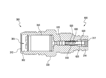
initiator assembly 700. The initiator assembly 700 may be identical to the
initiator assembly
600 except that the first end 712 of the bulkhead body 715 is "blank."
[0119] As can be seen, a novel initiator assembly is provided. In both
initiator assembly
600 and initiator assembly 700, the respective bulkheads 510, 710 help protect
the electronics
(switch housing 350 and addressable switch 360) from damage that might
otherwise occur as
a result of burning and a build-up of resultant soot in the initiator chamber
620 when the
explosive component 628 is set off.
[0120] All electrical connections for the initiator assembly may be made
without the use
of soldering or welding connections. Wire 632 of the igniter 630 is placed in
a receiving bore
of signal transmission pin 720. A crimp is then applied to the signal
transmission pin locking
the wire 632 in place. The ground wire 634 of the igniter 630 is wrapped
around the non-
conductive downstream end 714 of bulkhead body 715. The conductive metallic
ignition
chamber tube 620 is crimped over the downstream bulkhead end 714, making an
electrical
connection with ground wire 634 and retaining it in place. This allows a clean
path from the
ground wire 634, to the tube, to the cage, to the firing head 300, and return
to the surface 105.
[0121] Figures 9A and 9B together present a flow chart showing steps for a
method 900
of setting a tool in a wellbore. The tool is preferably a frac plug or a
packer.
[0122] In one aspect, the method 900 first comprises providing a firing
head. This is shown
in Box 910. The firing head may be in accordance with the firing head 300
discussed above.
[0123] The method 900 next includes placing a switch housing into an
upstream chamber
of the firing head 300. This is provided in Box 915. Along with this, an
addressable switch is
24
Date Regue/Date Received 2023-07-24
Utility Patent Application Customer No. 65,770
XConnect, LLc
placed inside of the switch housing. This is seen in Box 920. The switch
housing may be in
accordance with switch housing 350 shown above, while the addressable switch
may be in
accordance with addressable switch 360.
[0124] The method 900 further comprises providing a bulkhead in a
downstream chamber
of the firing head. This is indicated at Box 925. The bulkhead may be in
accordance with
either of bulkheads 510 or 710 described above. In this respect, the bulkhead
houses an
elongated signal transmission pin. The elongated signal transmission pin may
be in accordance
with the brass pin 520 described above.
[0125] The method 900 also comprises providing an ignition tube. This is
shown in Box
930. The ignition tube also resides within the downstream chamber of the
firing head. The
ignition tube may be in accordance with the ignition tube 620 of Figure 6A. Of
interest, an
upstream end of the ignition tube receives a downstream end of the signal
transmission pin.
Preferably, the upstream end of the ignition tube is crimped onto a downstream
end of the
bulkhead.
[0126] The method 900 further includes electrically connecting an upstream
end of the
signal transmission pin to the addressable switch. This is provided in Box 935
of Figure 9B.
Similarly, the method 900 includes electrically connecting the downstream end
of the signal
transmission pin to an igniter. This is shown in Box 940. The igniter also
resides within the
ignition tube.
[0127] In one aspect, the method 900 next includes attaching the firing
head to a lowermost
perforating gun along a perforating gun assembly. This is seen in Box 945. In
this instance,
the firing head acts as a tandem sub, threadedly connecting a gun barrel
housing to a setting
tool.
[0128] The method 900 then comprises pumping the perforating gun assembly
and the
firing head into a wellbore. This is provided in Box 950. Of course, the
setting tool and the
Date Regue/Date Received 2023-07-24
Utility Patent Application Customer No. 65,770
XConnect, LLc
plug (or other settable device such as a packer) are pumped into the wellbore
with the
perforating gun assembly at the end of an e-line 240.
[0129] The method 900 then includes sending an actuation signal from the
surface via the
e-line 240 and down to the signal pin in the bulkhead. This is indicated at
Box 955 of Figure
9B. The actuation signal is further sent to the igniter. This is shown in Box
960.
[0130] The result of sending the actuation signal to the igniter is that an
explosive
component 628 is initiated which, in turn, initiates a power charge in the
setting tool. This is
seen at Box 965. This, in turn, causes a plug or a packer to be set in the
wellbore. The
perforating gun string, including the firing head, may then be pulled from the
wellbore up to
the surface or accompanying perforating guns may be fired.
[0131] It is observed that the igniter is initiated before the upstream
guns are fired. Once
a gun is fired the operator is no longer able to communicate with the plug
switch and igniter.
[0132] The disclosed embodiments provide methods and systems for setting a
plug within
a wellbore. It should be understood that this description is not intended to
limit the invention.;
on the contrary, the exemplary embodiments are intended to cover alternatives,
modifications,
and equivalents, which are included in the spirit and scope of the invention
as defined by the
appended claims. Further, in the detailed description of the exemplary
embodiments,
numerous specific details are set forth in order to provide a comprehensive
understanding of
the claimed subject matter. However, one skilled in the art would understand
that various
embodiments may be practiced without such specific details.
[0133] Further, variations of the initiator and detonation system and of
methods for using
the initiator system within a wellbore may fall within the spirit of the
claims, below. It will be
appreciated that the subject matter disclosed herein are susceptible to other
modifications,
variations, and changes without departing from the spirit thereof.
26
Date Regue/Date Received 2023-07-24