Note: Descriptions are shown in the official language in which they were submitted.
1
APPARATUS FOR REPLACING PRINTING SLEEVES
The present invention relates to an apparatus for replacing printing
sleeves.
As is known, rotary printing machines have a plurality of rotating
cylinders for transferring inks onto a ribbon of material in sheet form to be
printed.
In particular, flexographic printing machines are known which have,
on a supporting structure, a central drum that pulls the material in sheet
form to be printed.
About the drum central a plurality of print assemblies are arranged,
each one constituted by a plate cylinder, which is arranged adjacent to the
central drum, and by an anilox roller, which transfers the ink to the plate
cylinder.
Nowadays, plate cylinders are constituted by a supporting shaft,
commonly known as a sleeve-holding shaft, which is mounted so that it can
rotate on the supporting structure of the machine, and onto which a printing
sleeve, which bears the image to be printed in relief, is removably engaged,
fitted axially.
Optionally, the printing sleeve can in turn be constituted by a tubular
holder, called a "carrier sleeve", over which a thinner printing sleeve,
called
a sleeve plate, is fitted, on the external surface of which the actual plate
is
present.
For each change of the images to be printed, it is necessary to
dismount the printing sleeves mounted on the machine and substitute them
with other printing sleeves, taken from a dedicated magazine, which bear
the plate of the new images to be printed.
The operations to replace printing sleeves can be performed manually
with the machine stopped by at least one operator who is brought to the
print assemblies by way of a special mobile platform.
In order to facilitate the change of the printing sleeve to be removed
Date Recue/Date Received 2023-07-26
2
by the operators, printing machines are equipped with a special expulsion
device which is arranged on the opposite side with respect to the side of the
machine where the operators are located and which axially disengages the
printing sleeve from the supporting shaft just enough to allow the operators
to manually grip the printing sleeve and complete its extraction from the
supporting shaft.
Manual replacement of printing sleeves is, however, owing to their
weight, extremely laborious for the operators, with consequent exposure of
the operators to injury.
Furthermore, manual replacement requires long execution times, with
consequent negative impact on the productivity of the machine.
In order to overcome these drawbacks, apparatuses have been devised
that make it possible to automatically execute the operations to replace the
printing sleeves.
In particular, apparatuses for replacing printing sleeves have been
provided which comprise a handling device which is capable of removably
engaging, by way of one or more grip assemblies, the printing sleeve to be
replaced and is connected to an anthropomorphic robot, constituted by a
plurality of articulated arms, which can move the handling device between a
first position, in which the handling device is proximate to and aligned
coaxially with a sleeve-holding shaft of a printing machine, and a second
position, in which the handling device is for example proximate to and
aligned coaxially with a sleeve-holding support of a rack or, in any case, of
a magazine for storing printing sleeves.
In the apparatuses currently known, the handling device in general has
a grip assembly that is not capable of adapting its grip to the printing
sleeve
that it extracts, such that if it is required to extract a printing sleeve
that has
different dimensions from those for which the grip assembly of the handling
device is designed, it is necessary to replace the handling device.
The aim of the present invention is to provide an apparatus for
Date Recue/Date Received 2023-07-26
3
replacing printing sleeves which is capable of improving the prior art in one
or more of the above-mentioned aspects.
Within this aim, an object of the invention is to provide an apparatus
for replacing printing sleeves that can be adapted to the dimensions of the
printing sleeves to be replaced.
Another object of the invention is to provide an apparatus for
replacing printing sleeves that can offer the widest guarantees of reliability
and safety in its operation.
A Furthermore, another object of the present invention is to overcome
the drawbacks of the prior art in an alternative manner to any existing
solutions.
Another object of the invention is to provide an apparatus for
replacing printing sleeves that is relatively easy to implement and which can
be made at low cost.
This aim and these and other objects which will become better
apparent hereinafter are achieved by an apparatus for replacing printing
sleeves according to claim 1, optionally provided with one or more of the
characteristics of the dependent claims.
Further characteristics and advantages of the invention will become
better apparent from the detailed description that follows of a preferred, but
not exclusive, embodiment of the apparatus for replacing printing sleeves
according to the invention, which is illustrated for the purposes of non-
limiting example in the accompanying drawings wherein:
Figure 1 is a perspective view of the apparatus according to the
invention;
Figure 2 is a perspective view of a handling device of the apparatus
according to the invention;
Figure 3 is a perspective view from a different angle of the handling
device;
Figure 4 is a partially cross-sectional side view of the handling
Date Recue/Date Received 2023-07-26
4
device;
Figure 5 is a perspective view of a grip clamp of the handling device
with parts omitted for the sake of simplicity;
Figure 6 is a perspective view from a different angle of the grip
clamp, again with parts omitted for the sake of simplicity;
Figures 7 and 8 are longitudinal cross-sectional views of a supporting
assembly of the handling device in two different positions;
Figures 9 to 26 are partially cutaway side views of the handling device
in a sequence of steps of operation of the apparatus according to the
invention.
With reference to the figures, the apparatus for replacing printing
sleeves according to the invention, generally designated by the reference
numeral 1, comprises a handling device 2, which can be removably engaged
with a printing sleeve 3 to be replaced.
The apparatus according to the invention further comprises a
movement robot 4, which is advantageously constituted by an
anthropomorphic robot with multiple rotation axes. Alternatively, the
movement robot 4 can also be constituted by a Cartesian robot.
The movement robot 4 makes it possible, in particular, to move the
handling device 2 between a first position, in which the handling device 2 is
arranged proximate and substantially coaxial to a sleeve-holding shaft 5
associated with a printing machine, and a second position, in which the
handling device 2 is arranged substantially at a sleeve-holding support 6 of
a storage magazine of printing sleeves.
For example, the sleeve-holding support 6 can be constituted by a
cylindrical body of shape substantially similar to that of the sleeve-holding
shaft 5, which is mounted with its axis arranged substantially horizontally
on a rack or other supporting structure, and around which the printing sleeve
3 can be axially fitted.
The printing machine, not shown, can be, for example, a flexographic
Date Recue/Date Received 2023-07-26
5
printing machine provided with a central drum, over which the material in
sheet form to be printed passes, and around which a plurality of print
assemblies are arranged, each one is provided with a plate roller, arranged
adjacent to the central drum and constituted by a sleeve-holding shaft 5 onto
which a printing sleeve 3 is fitted which bears the plate on its external
lateral surface.
Adjacent to the roller plate of each printing assembly is an anilox
roller, whose function is to transfer the ink onto the roller plate and which
in
turn can be implemented by a second sleeve-holding shaft onto which an
anilox sleeve is fitted.
The printing sleeve 3 of the roller plate can, in turn, be constituted by
a single sleeve element or it can be provided by two parts coupled together
and, in particular, by a tubular holder or carrier sleeve, which provides the
necessary rigidity to the printing sleeve, and by a smaller, external printing
sleeve, fitted around the carrier sleeve, which constitutes the sleeve plate
and which bears the actual plate.
In the present description, the term "printing sleeve" can also mean a
carrier sleeve, a sleeve plate or even an anilox sleeve.
Conveniently, on the sleeve-holding shaft 5 there can be, as is per se
known, a reference pin, arranged in a preset angular position with respect to
the axis of the sleeve-holding shaft and engageable in a corresponding
abutment recess, which is defined in the printing sleeve 3 in order to
provide a reference point for mounting the printing sleeve 3 in the correct
angular position, with respect to the sleeve-holding shaft.
It should be noted that the printing machine is advantageously
provided, in a per se known way, with at least one expulsion device, for
example of the pneumatic type, which can be actuated on command to
move, axially with respect to the sleeve-holding shaft 5, the printing sleeve
3 mounted on the sleeve-holding shaft 5, so as to make it protrude, with an
axial portion thereof, from the end of the sleeve-holding shaft 5 located on
Date Recue/Date Received 2023-07-26
6
the side of the printing machine on which the handling device 2 is intended
to operate. Advantageously, also at the magazine of printing sleeves,
expulsion means can be provided which are capable of acting on the
printing sleeves 3 mounted on sleeve-holding supports 6 in order to partially
extract the printing sleeve 3 from the corresponding sleeve-holding support
6.
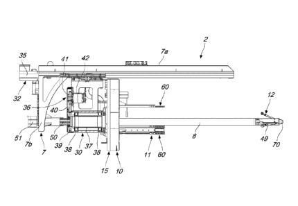
According to the invention, the handling device 2 comprises a
supporting frame 7, which is connected to the movement robot 4, in
particular, to the free end of the end arm 4a of the movement robot 4.
The supporting frame 7 supports a supporting rod 8, which protrudes
in a cantilevered manner from the supporting frame 7.
In particular, the supporting rod 8 can be positioned by the movement
robot 4 in a position aligned substantially coaxially with respect to the axis
of the sleeve-holding shaft 5 of the printing machine, and can be axially
introduced with play into the internal cavity 3a of the printing sleeve 3.
The supporting frame 7 can comprise, for example, a coupling plate-
like structure 7a with the movement robot 4, which has a longitudinal
extension and can be connected to the movement robot 4 with a face thereof
that is designed to be directed upward.
From the opposite face of the coupling plate-like structure 7a, a
supporting bracket 7b protrudes advantageously downward and the
supporting shaft 8 extends from that, and in turn extends below the plate-
like structure 7a and substantially parallel to the longitudinal extension of
the latter.
Also according to the invention, the handling device 2 further
comprises a self-centering grip clamp 10, which is supported by the
supporting frame 7 and is provided with engagement means 11 arranged
around the axis of the supporting rod 8.
In particular, the grip clamp 10 is able to move on command, with
respect to the supporting frame 7, along a movement direction that is
Date Recue/Date Received 2023-07-26
7
substantially parallel to the axis of the supporting rod 8, between at least
one advanced working position, in which the grip clamp 10 is arranged
substantially proximate to the free end of the supporting rod 8, and at least
one retracted working position, which is arranged spaced apart along the
axis of the supporting rod 8 with respect to the advanced working position,
in the direction of the other end of the supporting rod 8.
Conveniently, the distance along the axis of the supporting rod 8
between the advanced working position and the retracted working position
of the grip clamp 10 is substantially greater than or equal to the length of
the
printing sleeve 3.
The engagement means 11 of the clamp 10 can, in turn, move on
command between at least one inactive position, in which they are closer to
the axis of the supporting rod 8, in order to allow their insertion into or
extraction from the internal cavity 3a of the printing sleeve 3, and at least
one active position, in which they are radially spaced apart from the axis of
the supporting rod 8, in order to allow their engagement with the internal
surface of the printing sleeve 3.
It should be noted that the extent of the excursion performed by the
engagement means 11 in their transition between the inactive position and
the active position and, more specifically, the minimum and maximum
distance that the engagement means 11 can assume with respect to the axis
of the supporting shaft 8, in the transition from the inactive position to the
active position, can be set so as to make it possible for the grip assembly 10
to engage, by way of the engagement means 11, printing sleeves 3 of any
dimension, in particular printing sleeves 3 that have an inside diameter of
any dimension.
Substantially at the free end of the supporting rod 8 there is,
advantageously, a supporting assembly 12 for supporting the printing sleeve
3, which is provided with sliding support means 13 which can move on
command between a folded or retracted condition, in which they are close to
Date Recue/Date Received 2023-07-26
8
the axis of the supporting rod 8, so as not to interfere with the printing
sleeve 3, and an expanded or extended condition, in which they are further
away from the axis of the supporting rod 8, so as to be slideably engageable
by the internal surface of the printing sleeve 3.
Advantageously, the grip clamp 10 is, furthermore, actuatable in
rotation about the axis of the supporting rod 8, in order to facilitate the
dismounting and the mounting of the printing sleeve 3 and enable the
correct ensheathing thereof on the sleeve-holding shaft 5 of the printing
machine or on the sleeve-holding support 6 of the magazine, as will also be
explained below.
In greater detail, as can be seen in particular in Figure 5, the grip
clamp 10 comprises a base body 15, which is mounted around the
supporting rod 8, with the ability to slide along the axis of that supporting
rod.
The base body 15 conveniently comprises a sheet-like element 15a,
which is, for example, substantially star-shaped or trilobate-shaped, and
which is arranged, with its plane of arrangement, substantially perpendicular
to the axis of the supporting rod 8.
The sheet-like element 15a also has an opening 15b in the center,
which is slideably passed through by the supporting rod 8.
In turn, the engagement means 11 of the grip clamp 10 comprise at
least three grip claws 16, which are supported by the base body 15 and are
distributed mutually angularly spaced apart, around the axis of the
supporting rod 8.
Preferably, the grip claws 16 have an elongated extension along a
direction that is substantially parallel to the axis of the supporting rod 8
and
protrude in a cantilevered manner from the face of the base body 15 of the
clamp 10 that is directed toward the free end of the supporting rod 8.
Preferably, the surface of the grip claws 16 that is designed to come
into contact with the internal surface of the printing sleeve 3 is provided
Date Recue/Date Received 2023-07-26
9
with means for increasing the friction between the grip claws 16 and the
printing sleeve 3, which are constituted, for example, by a covering made of
elastically yielding material, such as rubber or the like.
The grip claws 16 can be moved slideably on command, with respect
to the base body 15, in a mutually synchronized manner, by way of
actuation means 18, along a respective direction of motion, substantially
perpendicular to the axis of the supporting rod 8, so as to obtain the
transition of the engagement means 11 from the inactive position to the
active position and vice versa.
More specifically, still with reference to Figure 5, the actuation means
18 of the grip claws 16 comprise, for each grip claw 16, an actuation
cylinder 20, supported by the base body 15 and connected with its stem to
the associated claw 16, which is mounted so that it can slide on a
corresponding sliding guide 21, fixed to the base body 15.
To ensure the synchronization of the movement of the claws 16, each
grip claw 16 is connected to a respective belt 22, running in a closed loop
between a pair of guide pulleys 23a, 23b that are mounted so that they can
rotate on the same side of the base body 15 where the claws 16 are located,
with the respective axes arranged substantially parallel to the axis of the
supporting rod 8, so as to define two branches of the belt 22 which are
substantially parallel to the movement direction of the corresponding claw
16, of which one is integrally connected to the corresponding claw 16.
One of the two guide pulleys, for example the one indicated with 23a,
is connected integrally in rotation with a respective synchronization cog
wheel 24, located on the side of the base body 15 opposite to the side on
which the grip claws 16 are located.
As can be seen in Figure 6, the synchronization cogs 24 of the various
grip claws 16 are connected to each other by way of a toothed
synchronization belt 25 which meshes with the synchronization cog wheels
24 in order to transmit the movement of each synchronization cog wheel 24
Date Recue/Date Received 2023-07-26
10
to the others, thus ensuring the synchronization of movement between the
grip claws 16.
Advantageously, the grip claws 16 are associated with at least one
position sensor, which can be, for example, provided by a linear transducer
which is mounted on one of the actuation cylinders 20 in order to identify
the exact position of the grip claws 16.
With reference in particular to Figures 2, 3 and 4, the base body 15 of
the grip clamp 10 is, conveniently, supported by a carriage 30, which is
slideably mounted along at least one linear guide 31 which is supported by
the supporting frame 7 and extends substantially parallel to the axis of the
supporting rod 8.
In particular, the carriage 30 is slideably coupled to a pair of linear
guides 31, preferably of the prismatic type, which are fixed to the face that
is directed toward the supporting rod 8 of the plate-like structure 7a.
More specifically, the carriage 30 is actuatable in translation along the
linear guides 31 by movement means 32, which are supported by the
supporting frame 7.
As can be seen in Figure 3, the movement means 32 of the carriage 30
can be, for example, constituted by a preferably recirculating-ball endless
screw 33, which is supported so that it can rotate by the plate-like structure
7a. The endless screw 33 is engageable by at least one female thread
element 34, integral with the carriage 30, and is actuatable in rotation about
its own axis by an electric motor 35 supported by the plate-like structure 7a.
Advantageously, the base body 15 of the grip clamp 10 is actuatable
in rotation, about a rotation axis substantially parallel to the axis of the
supporting rod 8, with respect to the carriage 30, using motor means 36
which are supported by the carriage 30.
In particular, the sheet-like element 15a of the base body 15 of the
grip clamp 10 can rotate with respect to the supporting shaft 8 and is
connected, on its side opposite to the grip claws 16, to a hollow rotating
Date Recue/Date Received 2023-07-26
11
shaft 37, which is axially passed through by the supporting rod 8 and is
supported so that it can rotate by the carriage 30 by way of the interposition
of bearings 38.
As shown in Figure 4, a kinematic transmission cog wheel 39 is
rigidly fixed at the end of the hollow rotating shaft 37 opposite to the end
connected to the base body 15 of the grip clamp 10, and a flexible motion
transmission element 40 runs around it, such as, for example, a toothed belt,
a chain or the like, which is moved by a pinion 41, which in turn is actuated
rotationally by an actuation motor 42, supported by the carriage 30 and
conveniently constituted by an oscillating rotary pneumatic actuator,
capable for example of performing oscillations preferably of around 270 in
one direction and in the other.
With reference in particular to Figures 7 and 8, the above-mentioned
supporting assembly 12 and, more specifically, the sliding support means 13
are, advantageously, provided by at least three supporting arms 45, which
are distributed around the axis of the supporting rod 8.
Each one of the supporting arms 45 is, in particular, pivoted, at an
intermediate portion thereof, to the supporting rod 8, about a respective
oscillation axis 45a that is substantially perpendicular to a radial plane
that
passes through the longitudinal axis of the corresponding supporting arm 45
and through the axis of the supporting rod 8.
The supporting arms 45 are furthermore functionally connected, at an
end thereof, to actuation means 46, which are supported by the supporting
frame 7 and which can be activated on command in order to cause the
rotation of the supporting arms 45 around the respective oscillation axes
45a, so as to obtain the transition of the sliding support means 13 from the
retracted condition to the extended condition and vice versa.
Advantageously, the supporting arms 45 support, at their end opposite
to the end connected to the actuation means 46, a respective supporting
wheel 48, which is slideably engageable against the internal surface of the
Date Recue/Date Received 2023-07-26
12
printing sleeve 3.
Conveniently, on the external lateral surface of the supporting rod 8,
respective accommodation grooves 49 are defined at each one of the
supporting arms 45, and are designed to receive the corresponding
supporting arm 45 when the sliding support means 13 are in the folded
condition.
Advantageously, the actuation means 46 of the supporting arms 45 are
constituted by an actuation rod 50, which is slideably accommodated along
the axis of the supporting shaft 8 and is connected, with one of its ends, to
a
linear actuator 51, such as, for example, a pneumatic cylinder, supported by
the supporting frame 7 at the opposite end with respect to the free end of the
supporting rod 8, and with its other end to each one of the supporting arms
45, by way of a respective lever mechanism 52.
Advantageously, the grip clamp 10 is provided with position sensing
means 55, which are constituted, for example, by a laser sensor, capable of
detecting the presence of the printing sleeve 3 proximate to the grip clamp
10.
Conveniently, the position sensing means 55 are, furthermore,
structured to allow the possibility of measuring the diameter of the printing
sleeve 3 and have, advantageously, a detector 55a, which is positioned
protruding from the base body 15 of the grip clamp 10, so as to be spaced
apart axially with respect to the face of the sheet-like element 15a on which
the grip claws 16 are located, and which is arranged so as to be able to face
toward the external surface of the printing sleeve, in order to be able to
detect its presence, when the grip clamp 10 is brought to its advanced
position.
In particular, such position sensing means 55 are functionally
connected to control means 56, which are constituted, conveniently, by an
electronic controller, which is mounted, preferably, on the supporting frame
7.
Date Recue/Date Received 2023-07-26
13
The control means 56 are configured to drive the movement means 32
of the carriage 30 that supports the grip clamp 10, as a function of the
signals arriving from the position sensing means 55, so as to command the
arrest of the carriage 30, during the movement of the grip clamp 10 from the
retracted working position to the advanced working position, upon the
detection, by the position sensing means 55, of the presence of the printing
sleeve 3 proximate to that grip clamp.
Advantageously, the control means 56 are also functionally connected
to the position sensor of the grip claws 16, so as to enable the control means
56 to detect, as a function of the signals originating from the position
sensor, the arrest of the grip claws 16, during their movement from the
inactive position to the active position, after the grip claws 16 have come
into contact with the internal surface of the printing sleeve 3 with the
consequent stop of the movement of those grip claws.
Conveniently, the grip clamp 10 is further fitted with pressure sensing
means, which are in turn functionally connected to the control means 56 and
are designed to detect the pressing exerted by the grip claws 16 against the
internal surface of the printing sleeve 3.
In particular, the control means 56 are configured to drive the
actuation means 18 of the grip claws 16, as a function of the signals arriving
from the pressure sensing means.
More specifically, the control means 56 are, advantageously,
configured to command the actuation means 18 of the grip claws 16, so that
the contact pressure exerted by the grip claws 16 against the internal surface
of the printing sleeve 3 and detected by the pressure sensing means is
proportional to the thickness of the printing sleeve 3.
It should be noted that the value of the thickness of the printing sleeve
3 can be calculated by the control means 56 on the basis of the signals
supplied by the position sensor of the grip claws 16 and on the basis of the
measurement of the outside diameter of the printing sleeve 3, which can be
Date Recue/Date Received 2023-07-26
14
supplied by the position sensing means 55 of the carriage 30.
Advantageously, according to the preferred embodiment, the pressure
sensing means are provided by an electro-pneumatic transducer adapted to
detect the feed pressure of the actuation cylinders 20 of the grip claws 16,
while the control means 56 are configured to drive a solenoid valve that
makes it possible to adjust the feed pressure of the actuation cylinders 20 so
that it is proportional to the value of the thickness of the printing sleeve 3
calculated by those control means.
The force with which the sliding support means 13 are brought from
the retracted position to the extended position can also be controlled by way
of an electro-pneumatic transducer which makes it possible to adjust the
feed pressure of the linear actuator 51 as a function of the thickness of the
printing sleeve 3, calculated by the control means 56.
Conveniently, the grip claws 16 have elastic pusher means 60, which
are engageable against the end of the printing sleeve 3 that is designed to be
directed toward the handling device 2.
As can be seen in particular in Figure 5, such elastic pusher means 60
comprise, for example, for each grip claw 16, a respective pusher pad 61,
facing the free end of the corresponding grip claw 16, and slideably
connected to the corresponding grip claw 16, for example by way of a pair
of supporting bars 61a.
The pusher pad 61 is elastically loaded by springs 62, which are
mounted around the supporting bars 61a and interposed between the pusher
pad 61 and the corresponding grip claw 16, and which act in the direction
which is adapted to keep the pusher pad 61 in the position spaced apart from
the corresponding grip claw 16.
Advantageously, at the free end of the supporting rod 8 there are axial
coupling means which are removably engageable with the axial shank of the
sleeve-holding shaft 5 of the printing machine at which the handling device
2 is positioned by the movement robot 4, so as to ensure the coaxial
Date Recue/Date Received 2023-07-26
15
arrangement between the supporting rod 8 and the sleeve-holding shaft 5.
Preferably, such axial coupling means comprise an engagement pin
70, which conveniently is frustum-shaped and protrudes axially from the
free end of the supporting rod 8.
The engagement pin is removably engageable in an engagement seat
71, which is correspondingly shaped and defined axially in the axial shank
of the sleeve-holding shaft 5.
Conveniently, such axial coupling means can furthermore be coupled
removably with an axial element 72, shaped like a shank, which is provided
at the end of the sleeve-holding support 6 of the magazine from which the
printing sleeve 3 is unseated or seated.
The operation of the apparatus according to the invention is the
following.
With reference to Figures 9 to 17, in order to extract a printing sleeve
3 from a sleeve-holding shaft 5 of the printing machine and ensheathe it
onto a sleeve-holding support 6 of the magazine, the movement robot 4
initially brings the handling device 2 to the first position, so that it is
arranged at the sleeve-holding shaft 5 that supports the printing sleeve 3 to
be extracted, and positions the supporting rod 8 so as to mate the free end of
the supporting rod 8 with the axial shank of the sleeve-holding shaft 5, as
shown in Figure 9.
In this step, the sliding support means 13 of the supporting assembly
12 are in the retracted condition and the grip clamp 10 is in the retracted
working position.
Then, the expulsion device of the printing machine is activated so that
an axial portion of the printing sleeve 3 is made protrude with respect to the
end of the sleeve-holding shaft 5 directed toward the handling device 2, as
shown in Figure 10.
At this point, with the engagement means 11 of the grip clamp 10 in
the inactive position, the movement means 32 of the carriage 30 are
Date Recue/Date Received 2023-07-26
16
activated so as to move the grip clamp 10 from the retracted working
position to the advanced working position, so as to insert the grip claws 16
into the internal cavity 3a of the printing sleeve 3.
When the position sensing means 55 detect the presence of the
printing sleeve 3 proximate to the grip clamp 10, the control means 56
command the deactivation of the movement means 32 of the carriage 30, so
as to arrest the movement of the grip clamp 10.
At this point, the actuation means 18 of the grip claws 16 are activated
so as to bring the engagement means 11 of the grip clamp 10 from the
inactive position to the active position, as illustrated in Figure 11.
Once the grip claws 16 have made contact with the printing sleeve 3,
they stop, since they cannot move further, and their arrest is detected by the
control means 56 on the basis of the signals arriving from the position
sensor of those grip claws.
At this point, on the basis of the signals arriving both from the
position sensing means 55 and from the position sensor of the grip claws 16,
the control means 56 calculate the value of the thickness of the printing
sleeve 3 and command the actuation means 18 of the grip claws 16, so that
the contact pressure exerted by the grip claws 16 against the internal surface
of the printing sleeve 3 will have a value proportional to the value of the
thickness of the printing sleeve 3.
More specifically, the control means 56 act on the solenoid valve that
adjusts the feed pressure of the actuation cylinders 20 of the grip claws 16,
until the electro-pneumatic transducer (which detects the feed pressure of
the actuation cylinders 20) detects that the value of the feed pressure of the
actuation cylinders 20 has been reached that will ensure the desired contact
pressure exerted by the grip claws 16 against the internal surface of the
printing sleeve 3, proportional to the thickness of the printing sleeve.
Subsequently, the movement means 32 are activated to move the
carriage 30 so as to bring the grip clamp 10 to the retracted position.
Date Recue/Date Received 2023-07-26
17
While the carriage 30 executes this movement, the actuation motor 42
can optionally be activated in order to make the grip clamp 10 perform a
rotation about the axis of the supporting rod 8, in order to bring the
abutment recess of the printing sleeve 3 to a preset angular position, with
respect to the axis of the printing sleeve 3.
It is also possible to actuate the grip clamp 10 in rotation, alternately
in one direction and in the other, about the axis of the supporting rod 8,
during the movement of the grip clamp 10 to its retracted working position,
in order to facilitate the extraction of the printing sleeve 3 from the sleeve-
holding shaft 5.
Also during the movement of the carriage 30 that brings the grip
clamp 10 to the retracted position, the linear actuator 51 of the supporting
assembly 12 is actuated so as to bring the sliding support means 13 of the
supporting assembly 12 from the retracted position to the extended position,
so that the internal surface of the printing sleeve 3 can slide on the
supporting wheels 48.
Once the carriage 30 has brought the grip clamp 10 to the retracted
working position, the printing sleeve 3 is completely extracted from the
sleeve-holding shaft 5 and loaded on the handling device 2, as shown in
Figure 12.
The movement robot 4 then brings the handling device 2 to the second
position so that the printing sleeve 3 that was extracted from the printing
machine can be ensheathed onto a sleeve-holding support 6 present in the
magazine.
In this step, the sliding support means 13 are brought back to the
retracted position, in order to prevent bending of the supporting rod 8 which
could compromise the coupling between the supporting rod 8 and the
sleeve-holding support 6, as shown in Figure 13.
The movement robot 4 then deploys the handling device 2 to engage
the free end of the supporting rod 8 with the axial element 72 provided on
Date Recue/Date Received 2023-07-26
18
the sleeve-holding support 6, as shown in Figure 14.
At this point, the linear actuator 51 of the supporting assembly 12 is
activated, so as to bring the sliding support means 13 of the supporting
assembly 12 from the retracted position to the extended position, in order to
ensure that the printing sleeve 3 is centered with respect to the sleeve-
holding support 6, as shown in Figure 15.
Subsequently, the movement means of the carriage 30 are activated,
so as to move the grip clamp 10 to the advanced working position and so
begin ensheathing the printing sleeve 3 onto the sleeve-holding support 6 of
the magazine.
Immediately after the departure of the carriage 30, or in any case once
engagement of the printing sleeve 3 with the sleeve-holding support 6 has
begun, the linear actuator 51 is actuated so as to bring the sliding support
means 13 of the supporting assembly 12 back from the extended position to
the retracted position, in order to prevent their collision with the grip
clamp
10, as can be seen in Figure 16.
The carriage 30 continues in its movement, so as to fit the printing
sleeve completely over the sleeve-holding support 6 and, once the stroke
limit has been reached, the grip claws 16 of the grip clamp 10 are returned
to the inactive position, so as to allow the printing sleeve to remain on the
sleeve-holding support 6 of the magazine.
Optionally, after bringing the grip claws 16 to the inactive position
and after moving the grip clamp 10 to the retracted working position, until
the grip claws 16 are extracted from the internal cavity 3a of the printing
sleeve 3, the grip claws 16 of the grip clamp 10 can be moved to the active
position until the corresponding elastic pusher means 60 are brought to a
position facing the end face of the printing sleeve 3 and subsequently the
carriage 30 is actuated so as to move the grip clamp 10 to the advanced
working position in order to engage the elastic pusher means 60 of the grip
claws 16 against the end face of the printing sleeve 3, until the printing
Date Recue/Date Received 2023-07-26
19
sleeve 3 is ensheathed onto the sleeve-holding support 6 is completed, as
shown in Figure 17.
With reference to Figures 18 to 26, if a printing sleeve 3 is to be
extracted from the magazine and ensheathed onto a sleeve-holding shaft 5
of a printing assembly of the printing machine, the movement robot 4
initially brings the handling device 2 to the second position, so that the
handling device 2 can be at the sleeve-holding support 6 on which the
printing sleeve 3 to be extracted is located, and deploys the supporting rod 8
of the handling device 2 so as to engage the free end of the supporting rod 8
with the axial shank of the sleeve-holding support 6.
In this step, the sliding support means 13 of the supporting assembly
12 are in the folded condition, as shown in Figure 18.
If necessary the means of expulsion of the magazine are activated, so
as to partially extract the printing sleeve 3 from the sleeve-holding support
6, as shown in Figure 19.
At this point, with the grip claws 16 of the grip clamp 10 in the
inactive position, the movement means 32 of the carriage 30 are activated in
order to begin the movement of the grip clamp 10 from the retracted
working position to the advanced working position.
As shown in Figure 20, when the position sensing means 55 detect the
presence of the printing sleeve 3 proximate to the grip clamp 10, the
movement of the carriage 30 is stopped and the grip claws 16 are moved to
their active position, until the printing sleeve 3 becomes locked with respect
to the grip clamp 10, with a contact pressure between the grip claws 16 and
the internal surface of the printing sleeve 3 that is proportional to the
thickness of that printing sleeve.
At this point, the carriage 30 is moved so as to move the grip clamp
10 to its retracted working position and, during this movement, the sliding
support means 13 are brought to the extended condition, so that the
supporting wheels 48 can slideably engage the internal surface of the
Date Recue/Date Received 2023-07-26
20
printing sleeve 3, until the printing sleeve 3 is completely extracted from
the
sleeve-holding support 6 of the magazine, as shown in Figure 21.
The movement robot 4, with the sliding support means 13 in the
folded condition, in order to prevent bending of the supporting rod 8, at this
point brings the handling device 2 to the first position, so as to position it
at
the sleeve-holding shaft 5 that is adapted to receive the printing sleeve 3
that was extracted from the magazine, and deploys the supporting rod 8 of
the handling device 2 so as to mate its free end with the axial shank of the
sleeve-holding shaft 5, as shown in Figure 23.
Once the supporting rod 8 is mated with the axial shank of the sleeve-
holding shaft 5, the sliding support means 13 are brought to the extended
condition in order to center the printing sleeve 3 with respect to the sleeve-
holding shaft 5, as shown in Figure 24.
Subsequently, the carriage 30 is actuated in order to move the grip
clamp 10 to its advanced working position and so begin ensheathing the
printing sleeve 3 onto the sleeve-holding shaft 5.
As soon as the printing sleeve 3 comes into contact with the sleeve-
holding shaft 5, the sliding support means 13 are returned to the folded
condition.
At this point, while the grip clamp 10 continues its movement to the
advanced working position, the grip clamp 10 is actuated so as to rotate
about the axis of the supporting rod 8, alternately in one direction and in
the
other, preferably through an oscillation angle substantially of approximately
90 , so as to transmit a rotary motion to the grip clamp 10 about the axis of
the supporting rod, to make it easier to ensheathe it onto the sleeve-holding
shaft 5.
Once the printing sleeve 3 is ensheathed for at least one portion of its
length, preferably at least half, the grip clamp 10 is actuated so as to
rotate,
in order to orient the printing sleeve 3 according to the correct positioning
angle, with respect to the axis of the sleeve-holding shaft 5, and so ensure
Date Recue/Date Received 2023-07-26
21
that its abutment recess engages with the reference pin on the sleeve-
holding shaft 5.
The grip clamp 10, continuing its stroke toward the advanced working
position, almost completely ensheathes the printing sleeve 3 onto the sleeve-
holding shaft 5.
Subsequently, the grip claws 16 are brought back to the inactive
position and the grip clamp 10 is moved to the retracted working position so
as to retract the grip claws 16 from the axial cavity of the printing sleeve
3.
Once retracted from the axial cavity of the printing sleeve 3, the grip
claws 16 of the grip clamp 10 are moved to the active position until
corresponding elastic pusher means 60 are brought to a position facing the
end face of the printing sleeve 3.
At this point, the carriage 30 is actuated again so as to move the grip
clamp 10 to the advanced working position, ensuring that the elastic pusher
means 60 of the grip claws engage against the end face of the printing
sleeve 3, until the ensheathement of the printing sleeve 3 onto the sleeve-
holding shaft 5 is completed, as shown in Figure 26.
In practice it has been found that the invention fully achieves the
intended aim and objects and, in particular, attention is drawn to the fact
that the apparatus according to the invention, by virtue of the peculiar
handling device, makes it possible to replace printing sleeves of different
dimensions without being necessary in each instance to replace the handling
device.
It should be noted that the apparatus according to the invention can be
validly applied in the replacement of printing sleeves not only in
flexographic printing machines but also in other types of rotary printing
machines that use printing sleeves.
The invention, thus conceived, is susceptible of numerous
modifications and variations, all of which are within the scope of the
appended claims.
Date Recue/Date Received 2023-07-26
22
Moreover, all the details may be substituted by other, technically
equivalent elements.
In practice the materials employed, provided they are compatible with
the specific use, and the contingent dimensions and shapes, may be any
according to requirements and to the state of the art.
Date Recue/Date Received 2023-07-26