Note: Descriptions are shown in the official language in which they were submitted.
CA 03207866 2023-07-10
WO 2022/155218 PCT/US2022/012142
FLAME PROTECTED OPTIC
PRIORITY CLAIM
100011 The present application claims the benefit of priority of U.S.
Provisional
Patent Application Serial No. 63/136,367, titled "Flame Protected Optic,"
filed January
12, 2021, which is incorporated herein by reference.
BACKGROUND
[0002] The application relates to luminaires and components for luminaires.
[0003] Light fixtures, or luminaires, include electric light sources and
provide an
aesthetic and functional housing in both interior and exterior applications.
Sometimes,
where luminaires are used in environments containing flammable gas, legal
regulations
sometime require luminaires to qualify for safe use in such an environment.
Qualification
for safe use of the luminaire enclosure in an environment containing flammable
gas may
include a requirement that any flame resulting from ignition of flammable gas
in the
luminaire is encapsulated by the luminaire and prevented from reaching the
exterior of
the luminaire. That is, the requirement may be that the luminaire be flame
encapsulating
in that it is configured to encapsulate any flames originating within the
luminaire.
SUMMARY
[0004] According to an exemplary embodiment, a luminaire includes a flame
encapsulating luminaire enclosure.
BRIEF DESCRIPTION OF DRAWINGS
[0005] FIG. 1 is a sectional side view of a luminaire comprising a
luminaire enclosure.
[0006] FIG. 2 is a front view of a luminaire comprising a luminaire
enclosure.
[0007] FIG. 3 is a view of a pcb board, LED array, and LED protective lens
array
configuration including flame path gaps.
CA 03207866 2023-07-10
WO 2022/155218 PCT/US2022/012142
[0008] FIGS. 3a is a top view of an LED protective lens array.
[0009] FIGS. 3b is a side view of an LED protective lens array.
100101 FIGS. 3c is an underside view of an LED protective lens array
including flame
path gaps.
100111 FIG. 4 is a detailed view of a luminaire lens securing structure of
a luminaire
enclosure cover.
[0012] FIG. 5a is a top view of an LED protective lens array.
[0013] FIG. 5b is an underside view of an LED protective lens array
including flame
path gaps.
[0014] FIG. 5c is a side view of an LED protective lens array.
[0015] FIG. 5d is a detailed view of a LED protective lens design.
100161 FIG. 6a is a perspective view of a luminaire comprising a flame
encapsulating
luminaire enclosure.
[0017] FIG. 6b is a top view of a luminaire comprising a flame
encapsulating luminaire
enclosure.
100181 FIG. 6c is a sectional side view of a luminaire comprising a flame
encapsulating
luminaire enclosure.
[0019] FIG. 7a is a perspective view of a luminaire comprising a flame
encapsulating
luminaire enclosure.
[0020] FIG. 7b is a top view of a luminaire comprising a flame
encapsulating luminaire
enclosure.
100211 FIG. 7c is a sectional side view of a luminaire comprising a flame
encapsulating
luminaire enclosure.
2
CA 03207866 2023-07-10
WO 2022/155218 PCT/US2022/012142
[0022] FIG. 8a is a perspective view of an LED protective lens array clamp
plate.
[0023] FIG. 8b is a perspective view of an LED protective lens array clamp
plate.
[0024] FIG. 9a is a top view of a standalone battery indicator light lens.
[0025] FIG. 9b is a sectional side view of a standalone battery indicator
light lens.
DETAILED DESCRIPTION
[0026] Before any embodiments are explained in detail, it is to be
understood that
embodiments described and illustrated are not limited in their application to
the details
of construction and the arrangement of components set forth in the following
description
or illustrated in the following drawings. The embodiments described and
illustrated may
be practiced or carried out in various ways and other embodiments are
possible.
[0027] Also, it is to be understood that the phraseology and terminology
used herein
are for the purpose of description and should not be regarded as limiting. The
use of
"including," "comprising," or "having" and variations thereof are meant to
encompass the
items listed thereafter and equivalents thereof as well as additional items.
Unless
specified or limited otherwise, the terms "mounted," "connected," "supported,"
and
"coupled" and variations thereof are used broadly and encompass both direct
and indirect
mountings, connections, supports, and couplings. As used within this document,
the
word "or" may mean inclusive or. As a non-limiting example, if it were stated
in this
document that "item Z may comprise element A or B," this may be interpreted to
disclose
an item Z comprising only element A, an item Z comprising only element B, as
well as an
item Z comprising elements A and B.
[0028] Various embodiments described herein are directed to luminaire
components
that prevent flame transmission from the inside of a luminaire to the outside
of a
luminaire. In certain aspects, the luminaire can be used in an environment
containing
flammable gas, for example, in specialized lab work, testing applications, or
workspaces
containing flammable gas. The luminaire may comprise a luminaire enclosure and
3
CA 03207866 2023-07-10
WO 2022/155218 PCT/US2022/012142
include light emitter(s) configured to emit light directly through a luminaire
enclosure
lens. This application discusses components that can be used to prevent flame
transmission from the inside of a luminaire to the outside of a luminaire,
while allowing
one or more light emitters of the luminaire to transmit light from the
interior of the
luminaire to the exterior of the luminaire thereby creating a flame
encapsulating
luminaire. A configuration of the luminaire light emitters and light emitter
protective
lenses may be accomplished so that a lightweight, slim luminaire enclosure
that prevents
transmission of an internal flame to the exterior of the luminaire can be
accomplished
while still facilitating a transmission of light from the interior of the
luminaire enclosure
to the exterior of the luminaire enclosure. Accordingly, the components and
assemblies
described herein can be safely integrated with systems that operate in the
presence
flammable gas.
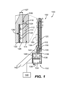
[0029] FIG. 1 illustrates a sectional side view of a redundantly flame
encapsulating
luminaire system 100 comprising a luminaire enclosure 102 including a
luminaire
enclosure backing 104 and a luminaire enclosure cover 106. The luminaire
enclosure
backing 104 and luminaire enclosure cover 106 are secured together in a manner
that
encapsulates any flame that may ignite within the luminaire enclosure 102 and
thereby
prevents any such flame from escaping the luminaire enclosure 102 at any point
at which
the luminaire enclosure backing 104 and luminaire enclosure cover io6 meet.
Moreover,
the luminaire enclosure 102, when assembled, is capable of fully encapsulating
any flame
that may ignite within the luminaire enclosure 102 according to a protective
standard for
enclosures. For example, the flame encapsulating protective standard of the
luminaire
enclosure 102 may be the Ex d standard.
[0030] In the embodiment shown, an encapsulating gasket io8 is disposed
between
the luminaire enclosure backing 104 and the luminaire enclosure cover io6,
thereby
further ensuring that no flame is transmitted from the inside of the luminaire
enclosure
102 to the outside of the luminaire enclosure 102. The luminaire enclosure
cover io6
includes a lens accommodating window 114 having at least an outer bezel lip
116. In the
embodiment shown, the luminaire lens 112 is cemented into place within a lens
accommodating window 114 of the luminaire enclosure cover io6, against the
outer bezel
4
CA 03207866 2023-07-10
WO 2022/155218 PCT/US2022/012142
lip 116, by a sealing agent 118. The sealing agent may be a silicone sealant
adhesive but
may include other sealing agents. A flame protected luminaire lens 112,
disposed in the
luminaire enclosure 102, allows light to be transmitted from the inside of the
luminaire
enclosure 102 to the outside of the luminaire enclosure 102 while also
maintains the flame
encapsulating protective standard of the luminaire enclosure 102.
[0031] In the embodiment shown, the plurality of LED arrays 120 is arranged
on a pcb
board 122. A plurality of LED protective lens arrays 124 are secured to the
luminaire
enclosure backing 104, through the pcb board 122. The LED protective lens
arrays 124 are
positioned over each of the LED arrays 120 and secured to the pcb board 122.
The
luminaire lens 112 is positioned at a distance from the LED protective lens
arrays 124 and
pcb board 122. In the embodiments shown, a spacer portion 127 of the assembled
luminaire enclosure 102 defines a luminaire cavity 128 between the LED
protective lens
arrays 124 and the luminaire lens 112 by mechanically preventing the movement
of the
luminaire lens 112 and the pcb board 122 toward one another within the
luminaire
enclosure 102. When fabricating the luminaire enclosure 102, the volume of the
luminaire
cavity 128 may be strategically determined based on a particular flame
encapsulating
protective standard. For example, if the Ex d protection standard is applied,
the volume
of the luminaire cavity 128 is minimized when fabricating the luminaire
enclosure 102.
For example, to adhere to a particular flame encapsulating standard, the
dimensions of
the luminaire enclosure cover and the luminaire enclosure backing may be
chosen so that
the height of the luminaire cavity (i.e., the distance between the luminaire
lens and the
luminaire enclosure backing) is between 5mm and 10 omm. Minimizing the volume
of the
luminaire cavity 128 while adhering to flame path and gap requirements imposed
by the
relevant flame encapsulating standard helps to reduce the required reference
pressure
that the luminaire enclosure 102 must withstand during an overpressure
test¨for
example, under the Ex d protection standard, in particular. In the embodiment
shown,
the LED protective lens arrays 124 mitigates the transmission of flames
resulting from the
ignition of flammable gas under the LED protective lens arrays 124 while the
luminaire
lens 112 may be configured to prevent transmission, to the exterior of the
luminaire
enclosure 102, of any flame resulting from ignition of within the luminaire
enclosure 102.
Additionally, a LED protective lens array clamp plate 111 is positioned over
the LED
CA 03207866 2023-07-10
WO 2022/155218 PCT/US2022/012142
protective lens arrays and fastened to the luminaire enclosure backing by a
mechanical
fastener 126, thereby clamping the LED protective lens arrays 124 to the pcb
board 122.
The LED protective lens array clamp plate 111 may be rigid or flexible, and
made of metal,
ceramic, plastic, or any other heat resistant or flame-resistant material. The
LED
protective lens array clamp plate 111 secures the LED protective lens arrays
124 to the pcb
board 122 so that no flames ignited under the LED protective lens array have
breathing
room to travel from under the LED protective lens array into the luminaire
cavity 128.
Therefore, in some embodiments, the entire luminaire enclosure 102 does not
necessarily
need to meet the relevant protective standard. That is, in some embodiments,
only the
LED protective lens arrays 124, pcb board 122 and LED protective lens array
clamp plate
111, in combination, need to meet the relevant protective standard (e.g.,
Flame
encapsulation, Ex d protection, Ex e protection, etc.).
[0032] In the embodiment shown, the luminaire enclosure backing 104
comprises a
heat conductive material and acts as a heatsink for the pcb board 122. The
luminaire
enclosure backing 104 acts as a mounting surface for the pcb board 122 and may
conduct
heat to the luminaire enclosure backing 104 via the mechanical fasteners (not
shown) or
via surface contacts or heat pipes. In some embodiments, the entire luminaire
enclosure
102 may be comprised of a lightweight, heat-conductive metal such as aluminum
or
titanium. In this way, the entire luminaire enclosure may be used as a
heatsink for the
LED arrays 120 and the pcb board 122 during operation of the luminaire system
100. In
some embodiments, only certain parts, such as limited portions of the
luminaire
enclosure backing 104 and luminaire enclosure cover io 6 comprise a heat-
conductive
material. In such embodiments, those certain parts may be used as localized
heatsinks. A
standalone heatsink 150 can be positioned in or on the luminaire enclosure 102
and draw
heat from the LED arrays 120 during operation. However, in most cases, the
luminaire
enclosure 102 is constructed of a heatsinking material such as a heat
conductive metal,
and the luminaire enclosure 102, itself, may therefore act as a heatsink for
the LED arrays
120 during operation.
[0033] In the embodiment shown, the luminaire system loo includes a
controls
enclosure 132 that encloses a lighting gearbox 134 and an LED driver 136.
Here, the
6
CA 03207866 2023-07-10
WO 2022/155218 PCT/US2022/012142
controls enclosure 132 is also qualified to encapsulate flames ignited within
the controls
enclosure 132. That is, the controls enclosure 132 comprises a controls
enclosure backing
138 and controls enclosure cover 139 that, when secured together, yield a seal
or flame
path that will prevent flames inside the controls enclosure 132 from reaching
the outside
of the controls enclosure 132 (e.g., Ex d protection qualified). In the
embodiment shown,
the controls enclosure 132 removably connects to the luminaire enclosure 102
via an
adaptor 140. In some embodiments, the adaptor 140 connects the controls
enclosure 132
to the luminaire enclosure 102 via electrical contacts. In other embodiments,
the adaptor
140 connects the controls enclosure 132 to the luminaire enclosure 102
wirelessly. In still
other embodiments, the adaptor 140 connects the controls enclosure 132 to the
luminaire
enclosure 102 via a removable or fixed wired connection.
[0034] In the embodiment shown, the lighting gearbox 134 is configured to
perform
analog regulation of an electrical input from a power source (not shown) and
output a
regulated electrical signal to the LED driver 136. The LED driver 136 may
deliver an
electrical signal to the LED arrays 120 based upon the regulated electrical
signal received
from the lighting gearbox 134, causing the LED arrays 120 to emit light.
[0035] One or more mounting components 142 may be disposed on one or more
portions of the luminaire enclosure 102. The mounting components 142 are
configured to
secure the luminaire enclosure 102 to a rod, a cord, a chain, or any other
known
component or assembly for attaching a luminaire to a surface or hanging it
therefrom.
The mounting components 142 can also be configured to connect the luminaire
enclosure
102 to a pole, post, ceiling, or other structure. Mounting components 142 may
also include
brackets having a pair of openings that receive fasteners to fasten the
luminaire enclosure
102 to a wall. Similar mounting components can also be used to secure the
controls
enclosure 132 to a surface.
[0036] The LED driver 136 may be disposed in the luminaire enclosure 102,
when
present, or in the controls enclosure 132, when present. The, lighting gearbox
134 may be
disposed in the luminaire enclosure 102 or in the controls enclosure 132,
similarly. A
power supply 146 may provide power to the luminaire enclosure 102 or controls
enclosure
132 and in turn the pcb board 122, the LED driver 136 and the LED arrays 120.
An LED
7
CA 03207866 2023-07-10
WO 2022/155218 PCT/US2022/012142
driver 136 provides a power signal to the LED arrays 120, causing them to emit
light. The
power supply 146 may be any combination of drivers, ballasts, or other power
supply
depending on the type of LEDs in the LED arrays 120. The LED driver 136 may be
a
separate component or may be integrated with a light engine on the same
circuit board as
the LED arrays 120. For example, the power supply 146 may be a power signal
corrector
including components such as a voltage regulator or bridge rectifier.
Additionally, the
power supply 146 may be an onboard or externally connected battery. In certain
aspects,
the luminaire enclosure may be connected to power supply 146 or connected
directly to
line power (not shown).
[0037] One or more control components 148, may be connected to or
integrated with
the luminaire system loo. The control components 148 can include backup
battery units,
fuses, microprocessors, FPGAs, surge protectors, wired or wireless
communication
modules (e.g., CAT5, radio, Wi-Fi, etc.), sensors (e.g., light, occupancy,
motion, heat,
temperature, etc.), or any combination thereof. In some embodiments, the
control
components 148 include components facilitating the connection of the luminaire
system
loo to a network that includes luminaire controllers, or one or more
controllers for
distributed communication and centralized control of the luminaire system loo.
[0038] Certain embodiments utilize reflectors, baffles, louvers or other
optical features
to direct light through the luminaire lens 112 during operation of the
luminaire system
loo. FIG. 1 shows an embodiment of a luminaire system 100 illustrated as a
linear
luminaire. In many embodiments, LED arrays 120 are positioned in the luminaire
enclosure 102 and configured to emit visible light directly through the
luminaire lens 112.
However, in other embodiments, reflectors, louvers, fiber optics, or baffles
may be used
to transmit light emitted by the LED arrays 120 through the luminaire lens 112
indirectly.
[0039] In some embodiments, a luminaire enclosure cover io6 secures the
luminaire
lens 112 to the luminaire enclosure backing 104, by sandwiching the luminaire
lens 112
between the luminaire enclosure cover io6 and luminaire enclosure backing 104
or an
extension of either (e.g., 116) when the luminaire enclosure 102 is tightened
closed by
enclosure fasteners (not shown). In other embodiments, the luminaire lens 112
is not
sandwiched between the luminaire enclosure backing 104 and the luminaire
enclosure
8
CA 03207866 2023-07-10
WO 2022/155218 PCT/US2022/012142
cover 106 when the enclosure is sealed by enclosure fasteners. Additionally,
in some
embodiments, the sealing agent cementing the luminaire lens 112 in or to the
luminaire
enclosure cover 106 can be replaced by mechanical fasteners, welds, etc.
Similarly, in
some embodiments, mechanical fasteners and enclosure fasteners may be replaced
by
adhesives, welds, etc. In other embodiments, the lens accommodating window 114
also
includes an inner bezel lip (not shown). In such embodiments, the luminaire
lens 112 may
be retained between the outer bezel lip 116 and the inner bezel lip of the
lens
accommodating window 114. In most embodiments, the luminaire lens 112 is
generally
planar in shape, but it is contemplated that the luminaire lens 112 may take
other shapes
and that other configurations may be used, and that the combination of the
means of
securing the luminaire lens 112, may still be qualified for use in
environments containing
flammable gases or under a flame encapsulating protective standard.
Additionally, the
luminaire lens 112 can be plain or it can have optical features (e.g.,
frosting, textured
surface, prisms, etc.) that alter or condition light emitted from a visible
light emitter, such
as a plurality of LED arrays 120. The luminaire lens 112 can also be used to
address color
mixing or color angle concerns.
[0040] In a number of embodiments, the encapsulating gasket io 8 may not
aid in
encapsulating a flame and in some embodiments may not be present. For example,
in
some embodiments, the encapsulating gasket may be configured primarily to
prevent the
ingress of dust or liquid into the luminaire enclosure 102. As yet another
example, in an
embodiment including the luminaire enclosure 102, the encapsulating gasket io8
may be
excluded from the luminaire enclosure 102 because, for a particular use of the
luminaire
system 100, there may be no need to prevent the ingress of dust or liquid into
the
luminaire enclosure 102.
[0041] In a number of embodiments, LED arrays 120 are not disposed in a
redundantly
flame-encapsulating luminaire system 100. In such cases, the LED arrays 120
may be
sufficiently flame protected by the use of LED protective lens arrays 124. In
some cases,
LED protective lens arrays 124 may be secured to pcb board 122 over LED arrays
120.
luminaire enclosure 102 may be entirely absent in such an embodiment, and LED
protective lens array clamp plate 111 may be used in concert with LED
protective lens
9
CA 03207866 2023-07-10
WO 2022/155218 PCT/US2022/012142
arrays 124 to perform sufficient flame encapsulation to provide a flame-
encapsulating
luminaire system loo without the use of luminaire enclosure 102. As another
example, in
embodiments lacking a luminaire enclosure 102, the encapsulating gasket io8 is
not used
in conjunction with the luminaire system 100. It is also contemplated herein
that a single
LED protective lens may be used, independent from an LED protective lens array
122, to
provide flame encapsulation for a single LED or light emitter, with or without
a luminaire
enclosure 102, by using the approaches taught herein.
[0042] FIG. 2 illustrates a front view of the luminaire system 200
including a luminaire
enclosure 202. Enclosure fasteners 230 are positioned along the perimeter edge
of the
luminaire enclosure cover 206. The even spacing of enclosure fasteners 230 may
help
ensure a flame-tight seal of the luminaire enclosure cover io6 against the
luminaire
enclosure backing 104, when such a flame-tight seal is desired. Similarly
controls
enclosure fasteners 230 are positioned at the corners of the controls
enclosure 232 and
may likewise ensure a flame-tight seal between the controls enclosure backing
138 and
the controls enclosure cover 239, when desired. Additionally, mechanical
fasteners 226
sandwich the pcb board 122 between the LED protective lens array clamp plate
211 and
the luminaire enclosure backing 104. In the embodiment shown, a plurality of
LED arrays
220, is clearly visible, and configured to emit light directly through the
luminaire lens 212,
when powered. Additionally, adaptors 240a, 240b ensure redundant, direct
communication between the luminaire enclosure 202 and the controls enclosure
232.
[0043] FIG. 3 illustrates a closeup view of the LED arrays 320 within of
the luminaire
system 200 is shown. In the embodiment shown, the LED protective lens arrays
324 are
tightly secured in over individual LED elements 323 of the LED arrays 320, by
mechanical
fasteners 226, 326, thereby creating a mechanical seal that disallows a flame
from
travelling into or out of any of the protective lenses 352, within the LED
protective lens
arrays 324. In some embodiments, the LED protective lens arrays 324 are
cemented into
place a by an LED protective lens array sealing agent (not shown) that aids in
making each
of the protective lenses 352, flame encapsulating. For example, the sealing
agent may be
a silicone sealant adhesive, but may include other sealing agents. In some
embodiments,
a flame-tight LED protective lens array gasket (not shown) may be used in
conjunction
CA 03207866 2023-07-10
WO 2022/155218 PCT/US2022/012142
with the LED protective lens arrays 324. In such cases, the LED protective
lens arrays
324, may be pressed down onto the LED protective lens array flame-tight
gasket, thereby
creating the aforementioned flame-tight seal. LED protective lens array clamp
plate 311
protects this arrangement and further ensures a flame-tight seal between the
LED
protective lens arrays 324, and the pcb board 222. This flame-tight seal is
indirectly
exhibited by flame path 354, shown in Fig. 3c on the underside of one of LED
protective
lens arrays 324. Further, the LED protective lens array clamp plate 311,
protects the LED
protective lens arrays 324 from deformation or movement during the ignition of
any
flammable gas within the luminaire enclosure 102, 202, or under the LED
protective lens
arrays 324.
[0044] As shown in FIGS 3a, 3h, and 3c, the LED protective lens array 324
includes
eight LED protective lenses 356 in a 2X2 configuration. Each LED protective
lens 356
includes an LED accommodating cavity 358. The LED protective lens array 324
also
includes a center aperture 360 configured to receive the mechanical fastener
226. The
LED protective lens array 324 also includes, at its corners, fastener
accommodating
cutouts 362. The LED protective lens array 324 is configured to be attached to
the pcb
board 222 by way of mechanical fasteners 126 interacting with the pcb board
222 via at
least one of the center aperture 360 and the fastener accommodating cutouts
362. The
LED accommodating cavities are 358 are configured to overlay and protect the
individual
LED elements 323 of the LED arrays 120 when the LED protective lens array 324
is placed
onto the pcb board 222.
[0045] FIG. 4 illustrates a luminaire enclosure cover 406 including an
encapsulating
gasket 408 a luminaire lens 412 and one of enclosure fasteners 430. The
luminaire
enclosure cover 406 may be configured to ensure that the luminaire enclosure
202 is
flame encapsulating when secured to the luminaire enclosure backing 104
according to
the methods and products described herein. For example, in the embodiment
shown, the
sealing agent 418 cements the luminaire lens 412 into the lens accommodating
window
214 of the luminaire enclosure cover 406. The sealing agent 418 may be flame-
tight, and
thereby create a flame-tight seal between the luminaire lens 112, 412 and the
luminaire
enclosure cover 406 that disallows flames from exiting the luminaire enclosure
202
11
CA 03207866 2023-07-10
WO 2022/155218 PCT/US2022/012142
between the luminaire lens 112, 412 and the luminaire enclosure cover 406.
Similarly, in
some embodiments, an encapsulating gasket 408 is flame-tight. In embodiments
wherein
the luminaire enclosure cover io6 is flame-tight, and the luminaire enclosure
cover io6
is flame-tight and comprises an encapsulating gasket 408 the entire luminaire
enclosure
202 becomes flame encapsulating when fastened together by the enclosure
fasteners 430.
[0046] FIGS. 5a, 5b, and 5c illustrate a LED protective lens array 524
including four
LED protective lenses 556 in a 2x2 configuration. Each LED protective lens 556
includes
an LED accommodating cavity 558. the LED protective lens array 524, and
includes a
center aperture 560 configured to receive the mechanical fastener 226. The LED
protective lens array 524 also includes, at its corners, fastener
accommodating cutouts
562 configured to be engaged by a mechanical fastener 126. The LED protective
lens array
524 is configured to be attached to the pcb board 222 by way of mechanical
fasteners 126
interacting with the pcb board 222 via at least one of the center aperture 560
and the
fastener accommodating cutouts 562. The LED accommodating cavities are 558 are
configured to overlay and protect the individual LED elements 323 of the LED
arrays 120
when the LED protective lens array 524 is placed onto the pcb board 222.
[0047] FIG. 5d illustrates a cross-section 562 of an embodiment of the led
protective
lens 556. In the embodiment shown, the LED accommodating cavity 558 includes
plurality of inner walls 564 forming tiered, concentric, conical cavities of
differing slopes,
diameters, and heights. In the embodiment shown, the outermost wall of the
plurality of
inner walls 564 has a diameter of 6.7 millimeters and a height of .84
millimeters; a second
wall, just above the outermost wall, has a diameter of 6.37 millimeters and
rises .64
millimeters above the outermost wall; a third wall, just above the second wall
has a
diameter of 3.97 millimeters and rises 1 millimeter above the second wall;
lastly, a final
wall, just above the third wall, rises .21 millimeters above the third wall,
has a diameter
of 2.06 millimeters, and comes to a closed, conical apex in the center of the
LED
accommodating cavity 558.
[0048] FIG. 6a and 6b illustrate a perspective view and a top view,
respectively, of the
luminaire system 600 including a luminaire enclosure 602. Enclosure fasteners
630
(screws, in the embodiment shown) are positioned along the perimeter edge of
the
12
CA 03207866 2023-07-10
WO 2022/155218 PCT/US2022/012142
luminaire enclosure cover 606. The even spacing of enclosure fasteners 630
help ensure
a flame-tight seal of the luminaire enclosure cover 606 against the luminaire
enclosure
backing 604. Additionally, mechanical fasteners 626a, 626b, 626c sandwich the
pcb
board 622 between the LED protective lens array clamp plate 611 and the
luminaire
enclosure backing 604. In the embodiment shown, a plurality of LED arrays 620
is
configured to emit light through the luminaire lens 612 when powered.
Additionally,
adaptors 664a, 664h provide channels for an exterior power or data source (not
shown)
to communicate electronically with a control board (not shown) of the
luminaire 602 or
with the pcb board 622. For example, a controls enclosure 232 may be
configured to
communicate with the luminaire 602 via the adaptors 664a, 664h and control the
LED
arrays 620 or the individual LED elements 623. The luminaire 602 also includes
a
standalone battery indicator light 668 configured to indicate a condition of
the battery
(e.g., a low charge condition, a charged condition, a damaged condition). As
will be
discussed in further detail below, a standalone flame protected LED optic
houses the
standalone battery indicator light 668 and provides flame protection for the
standalone
battery indicator light 668.
[0049] FIG. 6c illustrates a cross-section of the luminaire 602. In the
embodiment
shown, the luminaire 702 includes a hollow compartment 642 disposed on a
backside of
the luminaire enclosure backing 604. In the example shown, the hollow
compartment 642
contains mounting equipment 671 configured to mount the luminaire enclosure
backing
604 (and thereby the luminaire 602) to a surface (e.g., a wall, a ceiling, a
doorway). The
hollow compartment 642 may also be used for storage of electronic components
(e.g., a
battery, a controls circuit). In the embodiment shown, the volume of the
luminaire cavity
628 is determined to prioritize flame protection. Accordingly, the volume of
the luminaire
cavity 628 is minimized when fabricating the luminaire enclosure 602 so that a
flame
occurring in the luminaire cavity 628 is accordingly contained.
[0050] FIG. 7a and 7b illustrate a perspective view and a top view,
respectively, of
another luminaire system 700 including a luminaire enclosure 702. Enclosure
fasteners
730 are positioned along the perimeter edge of the luminaire enclosure cover
706. The
even spacing of enclosure fasteners 730 help ensure a flame-tight seal of the
luminaire
13
CA 03207866 2023-07-10
WO 2022/155218 PCT/US2022/012142
enclosure cover 706 against the luminaire enclosure backing 704. Mechanical
fasteners
726 fix the LED protective lens array clamp plate 711 over the pcb board 722
by
mechanically engaging the luminaire enclosure backing 704 through the pcb
board 722.
In the embodiment shown, a plurality of LED arrays 720 is configured to emit
light
through the luminaire lens 712. Additionally, aperture 770 provides a way for
an exterior
power or data source (not shown) to communicate electronically with a control
board (not
shown) of the luminaire 702 or with the pcb board 722, as described above,
with respect
to figure 6. As with the luminaire of figure 6, the luminaire 702 includes a
standalone
battery indicator light 768 configured to indicate a condition of the battery
(e.g., a low
charge condition, a charged condition, a damaged condition).
[0051] FIG. 7c illustrates a cross-section of the luminaire 702. In the
embodiment
shown, the luminaire 702 includes a slim enclosure cover 706 and a slim
luminaire
enclosure backing 704 joined together by enclosure fasteners 730 (pins, in the
embodiment shown). In the embodiment shown, the volume of the luminaire cavity
628
is determined to prioritize flame protection according to a flame protection
standard for
enclosures. Accordingly, the volume of the luminaire cavity 728 is minimized
when
fabricating the luminaire enclosure 702 so that a flame occurring in the
luminaire cavity
728 is accordingly kept relatively small. Aperture 770 is configured to
maintain the flame
protected status of the luminaire 702 by forming a flame-tight seal against
the materials
inserted therein (e.g., wires, a plug). In this way, the luminaire 702 may
remain slim and
while achieving flame protection as described herein.
[0052] FIGS. 8a and 8b illustrate LED protective lens array clamp plates
811a, 811b.
The LED protective lens array clamp plates 811a, 811b include fastener
apertures 870a,
870b configured to receive mechanical fasteners 726 for the purpose of
fastening the LED
protective lens array clamp plates to the luminaire enclosure backing 804. The
LED
protective lens array clamp plates 811a, 811b also include a plurality of LED
protective
lens apertures 872a, 872b configured to receive a variety of LED protective
lenses 756
therethrough when the LED protective lens array clamp plate 811a or 8nb is
fastened to
the luminaire enclosure backing 704 and sandwiches the LED protective lens
array 724
and pcb board 722 to the luminaire enclosure backing 704.
14
CA 03207866 2023-07-10
WO 2022/155218 PCT/US2022/012142
[0053] FIGS. 9a and 9b illustrate a standalone battery indicator light lens
974. The
standalone battery indicator light lens 974 comprises an indicator light
cavity 976
configured to receive a standalone battery indicator light 768 and to provide
flame
protection of the type described herein for the standalone battery indicator
light 768 when
clamped to the pcb board 722 via the LED protective lens array clamp plate
8na, 811b.
[0054] The foregoing detailed description of the certain exemplary
embodiments has
been provided for the purpose of explaining the general principles and
practical
application, thereby enabling others skilled in the art to understand the
disclosure for
various embodiments and with various modifications as are suited to the
particular use
contemplated. This description is not necessarily intended to be exhaustive or
to limit
the disclosure to the exemplary embodiments disclosed. Modifications may be
made to
adapt a particular situation or material to the teachings of the disclosure
without
departing from the scope thereof. Any of the embodiments and/or elements
disclosed
herein may be combined with one another to form various additional embodiments
not
specifically disclosed. Accordingly, additional embodiments are possible and
are
intended to be encompassed within this specification and the scope of the
appended
claims. The specification describes specific examples to accomplish a more
general goal
that may be accomplished in another way.
[0055] As used in this application, the terms "front," "rear," "upper,"
"lower,"
"upwardly," "downwardly," and other orientational descriptors are intended to
facilitate
the description of the exemplary embodiments of the present application, and
are not
intended to limit the structure of the exemplary embodiments of the present
application
to any particular position or orientation. Terms of degree, such as
"substantially" or
"approximately" are understood by those of ordinary skill to refer to
reasonable ranges
outside of the given value, for example, general tolerances associated with
manufacturing,
assembly, and use of the described embodiments.