Note: Descriptions are shown in the official language in which they were submitted.
WO 2022/174195
PCT/US2022/016468
PRE-COMBUSTION CO2 REMOVAL IN A NATURAL GAS FED STEAM METHANE
REFORMER (SMR) BASED HYDROGEN PLANT
CROSS-REFERENCE TO RELATED APPLICATIONS
[0001] This application claims the benefit of U.S. Patent
Application No. 17/176,050, filed on
February 15, 2021, entitled "Pre-Combustion CO2 Removal In A Natural Gas Fed
Steam Methane
Reformer (SMR) Based Hydrogen Plant", and is incorporated by reference herein
in its entirety.
TECHNICAL FIELD
100011 The present disclosure relates to processes for producing
hydrogen from natural gas.
BACKGROUND
100021 Currently, a majority of the hydrogen production is
accomplished using natural gas.
Carbon dioxide (CO2) can be present as part of the natural gas fed to the
hydrogen production
plant, and CO2 will also be generated within the plant (e.g., in a unit where
reforming and water
gas shift occur). Because carbon dioxide (CO2) is the main greenhouse gas that
is targeted for
reduction by various governments and various emissions programs, there is an
ongoing need for
the development of techniques for reducing carbon dioxide emissions.
SUMMARY
100031 A process for producing, hydrogen from natural gas, the
process comprising:
introducing a feed natural gas, a feed steam, and a fuel to a steam methane
reformer to produce
unshifted synthesis as (syngas); introducing the unshifted syngas to a water
gas shift unit to
produce a shifted syngas, removing CO2 from the shifted syngas to produce a
CO2 depleted
syngas and a (702 product; introducing the (702 depleted syngas to a. pressure
swing absorption
unit to produce a hydrogen product and an off-gas comprising carbon monoxide,
carbon dioxide,
1
CA 03208575 2023-8- 15
WO 2022/174195
PCT/US2022/016468
unreacted methane, and at least 25 raol% hydrogen based on a total motes of
components in the
off-gas, wherein the fuel that is introduced to the steam methane reformer
comprises the off-gas.
[0004] A process for producing hydrogen from natural gas, the
process comprising:
introducing a feed natural gas, a feed steam, and a .fuel to a steam methane
reformer to produce
unshifted synthesis gas (syngas); introducing the unshifted syngas to a water
gas shift unit to
produce a shifted syngas; removing CO2 from the shifted syngas to produce a
CO?, depleted syngas
and a CO2 product; introducing the CO2 depleted syngas to a pressure swing
absorption unit to
produce a hydrogen product; before removing CO2 from the shifted syngas,
cooling the shifted
syngas in a heat exchanger to remove an aqueous condensate from the shifted
syngas; removing
the aqueous condensate from a shifted syngas side of the heat exchanger;
introducing the aqueous
condensate to a coolant side of the heat exchanger; and producing a heat
exchanger steam in the
heat exchanger, wherein the heat exchanger steam is the feed steam that is
introduced to the steam
methane reformer.
[0005] A hydrogen production system comprising: a steam methane
reformer configured to
contact methane and steam with a catalyst to form an unshifted syngas; a water
gas shift unit
coupled to the steam methane reformer and configured to receive the unshifted
syngas from the
steam methane reformer and to produce a shifted syngas; an absorption unit
coupled to the water
gas shift unit and configured to receive the shifted syngas, remove carbon
dioxide from the shifted
syngas, and produce a CO2 depleted syngas and a CO2 product; a pressure swing
absorption unit
coupled to the absorption unit, wherein the pressure swing absorption unit is
configured to receive
the CO2 depleted syngas from the absorption unit and to produce a hydrogen
product and an off-
gas; and an off-gas stream coupled to the pressure swing absorption unit and
to the steam methane
reformer, wherein the off-gas stream is configured to receive the off-gas from
the pressure swing
2
CA 03208575 2023-8- 15
WO 2022/174195
PCT/US2022/016468
absorption unit and to introduce the off-gas to the steam methane reformer,
wherein the off-gas in
the ofi-gas stream comprises carbon monoxide, carbon dioxide, unreacted
methane, and at least 25
mot% hydrogen based on a total moles of components in the off-gas stream.
[0006] A hydrogen production system comprising: a steam methane
reformer configured to
contact methane and steam with a catalyst to form an unshifted syngas; a water
gas shift unit
coupled to the steam methane reformer and configured to receive the unshifted
syngas from the
steam methane reformer and to produce a shifted syngas; a heat exchanger
coupled to the water
gas shift unit and to the steam methane reformer, wherein the heat exchanger
is configured to
receive the shifted syngas from the water gas shift unit, to cool the shifted
syngas, to remove an
aqueous condensate from the shifted syngas, and to provide the shifted syngas
without the aqueous
condensate for introduction to an absorption unit; the absorption unit coupled
to the water gas shift
unit and the heat exchanger and configured to receive the cooled shifted
syngas, remove carbon
dioxide from the shifted syngas, and produce a CO2 depleted syngas and a CO2
product; a pressure
swing absorption unit coupled to the absorption unit, wherein the pressure
swing absorption unit is
configured to receive the CO2 depleted syngas from the absorption unit and to
produce a hydrogen
product and an off-gas; and a coolant stream having an end coupled to a
shifted syngas side of the
heat exchanger and an opposite end coupled to a coolant side of the heat
exchanger, wherein the
coolant stream is configured to remove the aqueous condensate from the shifted
syngas side of the
heat exchanger and to introduce the aqueous condensate to the coolant side of
the heat exchanger,
wherein the heat exchanger is configured to heat the aqueous condensate to
produce a heat
exchanger steam, wherein the heat exchanger steam is fed to the steam methane
reformer.
[0007] The above processes and systems can have a carbon capture of
about 60%. When used
in conjunction with a flue gas treatment process and system having carbon
dioxide removal, where
3
CA 03208575 2023-8- 15
WO 2022/174195
PCT/US2022/016468
a splitter can be adjusted to control how much flue gas flows to another
absorption unit for carbon
dioxide removal from the flue gas, the carbon recovery of the combined process
and system can
range from about 60% to about 95%. The flue gas treatment process and system
can also include
another pressure swing absorption unit to produce an 02 product and a N2
product. The 02
product recovered by the flue gas treatment process and system can be fed to
the steam methane
reformer. The N2 product can be have nitrogen purity suitable for use in
another part of the plant
where the processes and systems disclosed herein are located.
[0008] While multiple embodiments are disclosed, still other
embodiments will become
apparent to those skilled in the art from the following detailed description.
As will be apparent,
some embodiments, as disclosed herein, are capable of modifications in various
aspects without
departing from the spirit and scope of the claims as presented herein.
Accordingly, the detailed
description hereinbel ow is to be regarded as illustrative in nature and not
restrictive.
BRIEF DESCRIPTION OF THE DRAWINGS
[0009] The following figures illustrate embodiments of the subject
matter disclosed herein.
The claimed subject matter may be understood by reference to the following
description taken in
conjunction with the accompanying figures, in which:
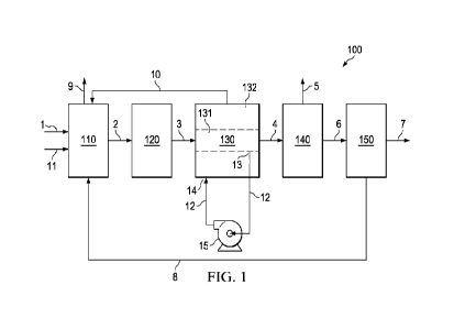
[0010] FIG. 1 illustrates a process and system for producing
hydrogen from natural gas.
[0011] FIG. 2 illustrates a process and system for treating the flue
gas produced in FIG. 1.
[0012] FIG. 3 illustrates a process and system for producing
hydrogen from natural gas,
without the pre-combustion carbon dioxide removal of FIG. 1.
DETAILED DESCRIPTION
[0013] It should be understood at the outset that although an
illustrative implementation of one
or more embodiments are provided below, the disclosed process and system may
be implemented
4
CA 03208575 2023-8- 15
WO 2022/174195
PCT/US2022/016468
using any number of techniques, whether currently known or in existence. The
disclosure should
in no way be limited to the illustrative implementations, drawings, and
techniques illustrated
hereinbelow, including the exemplary designs and implementations illustrated
and described
herein, but may be modified within the scope of the appended claims along with
their full
scope of equivalents. Thus, while multiple embodiments are disclosed, still
other embodiments
will become apparent to those skilled in the art from the following detailed
description. As will be
apparent, some embodiments, as disclosed herein, are capable of modifications
in various aspects
without departing from the spirit and scope of the claims as presented herein.
Accordingly, the
detailed description hereinbelow is to be regarded as illustrative in nature
and not restrictive.
[0014] The recitation of ranges of values herein is merely intended
to serve as a shorthand
method of referring individually to each separate value falling within the
range. Unless
otherwise indicated herein, each individual value is incorporated into the
specification as if it
were individually recited herein. All processes described herein can be
performed in any
suitable order unless otherwise indicated herein or otherwise clearly
contradicted by context.
The use of any and all examples, or exemplary language (e.g., "such as")
provided with respect
to certain embodiments herein is intended merely to better illuminate the
disclosure and does not
pose a limitation on the scope of the disclosed subject matter otherwise
claimed. No language in
the specification should be construed as indicating any non-claimed element
essential to the
practice of the disclosed subject matter.
[0015] Groupings of alternative elements or embodiments disclosed
herein are not to be
construed as limitations. Each group member can be referred to and claimed
individually or in any
combination with other members of the group or other elements found herein.
One or more
members of a group can be included in, or deleted from, a group for reasons of
convenience and/or
CA 03208575 2023-8- 15
WO 2022/174195
PCT/US2022/016468
patentability. When any such inclusion or deletion occurs, the specification
is herein deemed to
contain the group as modified.
100161 The following discussion provides many exemplary embodiments
of the disclosed
subject matter. Although each embodiment may represent a single combination of
disclosed
elements, the disclosed subject matter is considered to include all possible
combinations of the
disclosed elements. Thus, if one embodiment comprises elements A, B, and C,
and a second
embodiment comprises elements B and D, then the disclosed subject matter is al
so considered to
include other remaining combinations of A, B, C, or D, even if not explicitly
disclosed.
100171 While the following terms are believed to be well understood
by one of ordinary skill in
the art, the following definitions are set forth to facilitate explanation of
the presently disclosed
subject matter. Unless defined otherwise, all technical and scientific terms
used herein have the
same meaning as commonly understood to one of ordinary skill in the art to
which the presently
disclosed subject matter belongs.
100181 As used in the description herein and throughout the claims
that follow, the meaning
of "a," "an," and "the" includes plural reference unless the context clearly
dictates otherwise.
Also, as used in the description herein, the meaning of "in" includes "in" and
"on" unless the
context clearly dictates otherwise.
100191 As used herein, the terms "comprise,- "comprises,-
"comprising,- or any other
variations thereof, are intended to cover a non-exclusive inclusion, such that
a process or method
that comprises a list of steps does not include only those steps but may
include other steps not
expressly listed or inherent to such process or method. Similarly, one or more
devices or sub-
systems or elements or structures preceded by "comprises [...] a- does not,
without more
constraints, preclude the existence of other devices or other sub-systems or
other elements or
6
CA 03208575 2023-8- 15
WO 2022/174195
PCT/US2022/016468
other structures or additional devices or additional sub-systems or additional
elements or
additional structures.
100201 Reference throughout this specification to "one embodiment,"
"an embodiment," or
similar language means that a particular feature, structure, or characteristic
described in
connection with the embodiment is included in at least one embodiment of the
present
disclosure. Thus, appearances of the phrase "in one embodiment," "in an
embodiment," and
similar language throughout this detailed description may, but do not
necessarily, all refer to the
same embodiment.
100211 Disclosed herein is a process and system for producing
hydrogen from natural gas that
has cost effective carbon capture. To accomplish this, carbon dioxide is
removed in a pre-
combustion context, in that, the process and system separate carbon dioxide
from a shifted syngas,
and use a hydrogen enriched off-gas stream derived from pressure swing
absorption of the shifted
syngas as fuel for combustion in a steam methane reformer, in place of a
natural gas fuel. The pre-
combustion context is relative to carbon dioxide removal in a post-combustion
context, e.g., where
carbon dioxide is removed from the flue gas emitted from a steam methane
reformer, after
combustion of fuel in the steam methane reformer. The disclosed process and
system has further
improved carbon capture when optionally using the post-combustion carbon
dioxide removal
technique disclosed herein, which separates carbon dioxide from the flue gas
emitted by the steam
methane reformer.
100221 In the pre-combustion context disclosed herein, separation of
carbon dioxide from the
shifted syngas reduces the amount of carbon dioxide in the off-gas of the
pressure swing
absorption (PSA) unit that is fed as fuel to the steam methane reformer. This
means that when
using PSA off-gas as fuel as disclosed herein, the carbon dioxide is present
in off-gas recycle only
7
CA 03208575 2023-8- 15
WO 2022/174195
PCT/US2022/016468
in residual amounts (compared to no carbon dioxide recovery), so the heat duty
of the steam
methane reformer 110 needed for heating carbon dioxide in addition to other
components is
reduced, which reduces the fuel needed to heat the steam methane reformer 110
to maintain
operating temperature. Moreover, the carbon dioxide that would be passed
through to the flue gas
of the steam methane reformer is reduced to residual amounts.
100231 Using the hydrogen rich stream (hydrogen enriched PSA off-
gas) as fuel in place of a
hydrocarbon fuel reduces the amount of carbon dioxide generated due to fuel
combustion because
a smaller amount of hydrocarbon fuel is used. Combustion of hydrogen produces
no carbon
dioxide; thus, the flue gas that flows from the steam methane reformer
contains less carbon dioxide
(compared with using hydrocarbon-based fuels). The off-gas of the PSA unit can
contain greater
than 50 mol% hydrogen. Carbon dioxide that can be generated by other
components of the off-gas
in the steam methane reformer, and any carbon dioxide residually contained in
the PSA off-gas
that passes through the steam methane reformer, can flow from the steam
methane reformed in the
flue gas and optionally be captured from the flue gas by a flue gas treatment
system. Carbon
capture according to the process described herein can be improved over
existing techniques to be
in a range of from about 60% to about 95%.
100241 The process described herein can be implemented using the
system 100 of FIG. 1. The
system 100 includes a steam methane reformer 110; a water gas shift unit 120;
a shifted syngas
cooling unit 130; an absorption unit 140; and a pressure swing absorption
(PSA) unit 150. The
system 100 can optionally include the flue gas treatment system 200 in FIG. 2.
In FIG. 2, the flue
gas treatment system 200 can include a cooling unit 210, a compression unit
220, a carbon dioxide
recovery unit 230, and a pressure swing absorption (PSA) unit 240. As will be
appreciated by one
of skill in the art, and with the help of this disclosure, components of the
hydrogen production
8
CA 03208575 2023-8- 15
WO 2022/174195
PCT/US2022/016468
system can be in fluid communication with each other through any suitable
conduits (e.g., pipes,
streams, etc.).
100251 The process of FIG. 1 can include introducing natural gas and
steam to the steam
methane reformer 110 to produce an unshifted synthesis gas (syngas).
100261 In aspects, the natural gas in stream 1 can include methane
and one or more of C2+
hydrocarbons (e.g., ethane, propane, butanes, pentanes, or combinations
thereof), nitrogen, carbon
dioxide, and contaminants (e.g., sulfur-containing compounds, chlorides, water
vapor, or
combinations thereof). It is contemplated that the natural gas in stream 1 can
be pre-treated to
remove sulfur-containing compounds (e.g., hydrogen sulfide, carbon sulfide,
carbonyl sulfide,
carbon disulfide, organic sulfur compounds, or combinations thereof) to a
level acceptable to avoid
poisoning of the catalyst in the steam methane reformer 110. In aspects, the
concentration of
contaminants in stream 1 is less than about 1 part per million volume (ppmv),
alternatively less
than about 0.5 ppmv, or alternatively less than about 0.1 ppmv. In some
aspects, the concentration
of sulfur-containing compounds in stream 1 is less than about 1 part per
million volume (ppmv),
alternatively less than about 0.5 ppmv, or alternatively less than about 0.1
ppmv. In some aspects,
the concentration of hydrogen sulfide in stream 1 is less than about 1 part
per million volume
(ppmv), alternatively less than about 0.5 ppmv, or alternatively less than
about 0.1 ppmv.
100271 In aspects, steam can be introduced into the steam methane
reformer 110 via stream 11,
via stream 10, and optionally via stream 1. In an embodiment, a molar ratio of
steam to methane in
the total feed streams to the steam methane reformer 110 can be from about
0.5:1 to about 4.0:1,
alternatively from about 0.75:1 to about 3.0:1, or alternatively from about
0.8:1 to about 2.5:1. In
an embodiment, a molar ratio of steam to methane in the total feed streams to
the steam methane
reformer 110 can be from about 0.5:1 to about 1.0:1, alternatively from about
0.6:1 to about 0.9:1,
9
CA 03208575 2023-8- 15
WO 2022/174195
PCT/US2022/016468
or alternatively from about 0.65:1 to about 0.85:1, for a sulfur passivated
nickel-based catalyst in
the steam methane reformer 110. In an embodiment, a molar ratio of steam to
methane in the total
feed streams to the steam methane reformer 110 can be from about 2.5:1 to
about 4.0:1,
alternatively from about 2.75:1 to about 3.75:1, or alternatively from about
3.0:1 to about 3.5:1, for
a sulfur sensitive nickel-based catalyst in the steam methane reformer 110.
100281 In an embodiment, a molar ratio of carbon dioxide to methane
in the total feed streams
to the steam methane reformer 110 can be from about 0.5:1 to about 1.5:1,
alternatively from about
0.5:1 to about 1.0:1, or alternatively from about 1.0:1 to about 1.5:1. In an
embodiment, a process
of producing fuel from carbon dioxide avoids separating the carbon dioxide
from the natural gas
prior to introducing the natural gas to the steam methane reformer 110. In an
embodiment, a
process of producing fuel from carbon dioxide excludes separating at least a
portion of the carbon
dioxide from the natural gas prior to introducing the natural gas to the steam
methane reformer
110. Generally, in conventional reforming processes, at least a portion of the
carbon dioxide can
be separated (e.g., removed) from a feedstock introduced to a reforming unit,
as the carbon dioxide
lowers the molar ratio of hydrogen to carbon monoxide. Carbon dioxide can be
converted to
carbon monoxide in the presence of hydrogen, according to the general reaction
CO2 + H2 .=` CO + H20. In an embodiment, the steam methane reformer 110 as
disclosed herein
can employ carbon dioxide as part of a feedstock introduced to steam methane
reformer 110 (when
compared to conventional steam reforming processes), in order to produce a
syngas (e.g., unshifted
syngas) having a molar ratio of hydrogen to carbon monoxide of about 2:1.
Converting carbon
dioxide to carbon monoxide lowers the molar ratio of hydrogen to carbon
monoxide both by
consuming hydrogen and producing carbon monoxide. Further, the presence of
carbon dioxide can
lead to an additional methane reforming reaction as represented by the general
reaction
CA 03208575 2023-8- 15
WO 2022/174195
PCT/US2022/016468
CH4 -F CO2 .=µ 2C0 + 2H2, which in turn can lower the molar ratio of hydrogen
to carbon
monoxide in the syngas (e.g., unshifted syngas) by producing hydrogen and
carbon monoxide in
equimolar amounts.
100291 The steam methane reformer 110 can include one or more
vessels containing a catalyst.
The steam methane reformer 110 can generally include a reaction side and a
heating side, wherein
heat derived from combustion of a fuel on the heating side is used to supply
heat on the reaction
side where the methane reforming reaction occurs. For example, a vessel for
the steam methane
reformer 110 can contain one or more tubes loaded with catalyst, where the
interior of the tubes is
the reaction side of the steam methane reformer 110, and each tube is fluidly
connected with
streams 1, 2, and 11; while, the outer surface of the tubes is considered to
be on the heating side of
the steam methane reformer 110 and is subjected to heat generated from
combustion of a fuel that
is fed to and combusted on the heating side of the steam methane reformer 110.
100301 The steam methane reformer 110 is configured to contact the
feed natural gas receive
via stream 1 with the catalyst to produce the unshifted syngas (e.g., on the
reforming reaction side
of the steam methane reformer 110). In embodiments, the catalyst of the steam
methane reformer
110 can include a sulfur passivated nickel-based catalyst. Methane can be
reformed (e.g.,
converted to syngas or unshifted syngas) in the presence of water (e.g.,
steam) according to the
general reaction CH4 + H2O .=s CO + 3H2. The CO made in the reaction can also
be converted to
CO2 in the steam methane reformer 110, by the reaction in the presence of
water (e.g., steam)
according to the general reaction CO + H2O ,=µ CO2 + 1112. Conventional steam
methane reformers
use a steam to methane molar ratio of from about 2.5:1 to about 4.0:1,
resulting in a syngas with a
molar ratio of hydrogen to carbon monoxide of about 3:1, or higher. In an
embodiment, the steam
methane reformer 110 as disclosed herein can employ a low steam to methane
ratio of 0.5 to 2.0
11
CA 03208575 2023-8- 15
WO 2022/174195
PCT/US2022/016468
(when compared to conventional steam reforming processes) due to the presence
of CO2 in the
feed gas, in order to produce a syngas (e.g., unshifted syngas) having a molar
ratio of hydrogen to
carbon monoxide of about 2:1
100311 In an embodiment, the steam methane reformer 110 can comprise
any suitable reactor,
such as for example a tubular reactor, a multitubular reactor, and the like,
or combinations thereof
In an embodiment, the steam methane reformer 110 can comprise a MIDREX
reformer, which is
commercially available from Mi drex Technologies, Inc. In an embodiment, the
steam methane
reformer 110 can have a nickel-based catalyst (e.g., sulfur sensitive nickel-
based catalyst) and/or a
sulfur passivated nickel-based catalyst (to avoid carbon depositions)
contained therein. Methane
reforming (according to the general reaction CH4 + H20 ,=` CO + 3H2) is
strongly endothermic,
and a reaction rate depends on the temperature, pressure and catalyst type.
Methane will undergo
the reforming reaction at high temperatures; however, in the presence of a
catalyst (e.g., nickel-
based catalyst), the temperature at which methane can be reformed can be
lowered. In an
embodiment, the steam methane reformer 110 can comprise one or more catalyst
filled tubes (e.g.,
nickel-based catalyst filled tubes). In an embodiment, methane reforming can
take place in catalyst
filled tubes (e.g., nickel-based catalyst filled tubes). In such embodiment,
the catalyst filled tubes
can be heated indirectly, such as for example by burning a steam methane
reformer fuel inside a
reactor (e.g., fire box, furnace, etc.) comprising the catalyst filled tubes
(e.g., a tube-filled furnace).
100321 In aspects of this disclosure, the fuel include the off-gas
of the pressure swing
absorption unit 150 in system 100 (via stream 8 from the PSA unit 150,
discussed in more detail
below). When embodied as the off-gas from the PSA unit 150, the steam methane
reformer fuel
can include carbon monoxide, carbon dioxide, methane, hydrogen, and water
vapor. In additional
or alternative aspects, the off-gas stream 8 of the pressure swing absorption
unit 150 is the only
12
CA 03208575 2023-8- 15
WO 2022/174195
PCT/US2022/016468
fuel stream that is fed to the steam methane reformer 110 during steady state
operation (e.g., the
fuel to the steam methane reformer 110 consists of the off-gas from the
pressure swing absorption
unit 150).
100331 In aspects, the amount of hydrogen in the steam methane
reformer fuel that is fed to the
steam methane reformer 110 can be greater than 30, 35, 40, 45, or 50 mol%
based on a total moles
of components in the fuel that is fed to the steam methane reformer 110. In
additional aspects, the
amount of carbon dioxide in the steam methane reformer fuel (e.g., in off-gas
stream) can be less
than 60, 55, 50, 45, 40, 35, 30, 25, 20, 15, 10, 5, 4, or 3 mol% based on a
total moles of
components in the fuel that is fed to the steam methane reformer 110. In
additional aspects, the
amount of methane (e.g., in the form of unreacted methane passing through the
system 100 to the
off-gas of the PSA unit 150) in the steam methane reformer fuel that is fed to
the steam methane
reformer 110 can be greater than 10, 15, 20, 25, 30, 35, or 40 mol% based on a
total moles of
components in the fuel that is fed to the steam methane reformer 110.
100341 In some aspects, it should be understood that a natural gas
fuel may be used to startup
the steam methane reformer 110 during startup of the system 100; however, upon
reaching steady
state with the improved hydrogen and carbon dioxide concentrations in the off-
gas stream 8 of the
pressure swing absorption unit 150, the natural gas fuel may be discontinued
for steady state
operation, and the hydrogen in the off-gas stream 8 can supply the needed fuel
for the steam
methane reformer 110.
100351 In an embodiment, a flue gas can be emitted from the steam
methane reformer 110,
wherein the flue gas comprises combustion products generated by combustion of
the fuel that is
fed to the steam methane reformer 110, such as carbon dioxide and water vapor.
The steam
methane reformer fuel can be burned at a bottom of the steam methane reformer
110, and a flue
13
CA 03208575 2023-8- 15
WO 2022/174195
PCT/US2022/016468
gas stream 9 can be vented or emitted at the top of the steam methane reformer
110, wherein
furnace tubes filled with catalyst are dispersed within the furnace vessel
between fuel burners and
the flue gas vent/outlet stream 9. As will be appreciated by one of skill in
the art with the help of
this disclosure, the fuel burning (e.g., burner flames) and the fuel
combustion products do not
contact directly the feed natural gas travelling through and reforming within
the catalyst filled
tubes (e.g., nickel-based catalyst filled tubes). That is, the steam methane
reformer fuel burns
inside the steam methane reformer 110 and outside the catalyst filled tubes
where the reformation
reactions occur, and the fuel combustion products travel through the steam
methane reformer 110
and along an outer surface of the catalyst filled tubes towards the outlet for
the flue gas, which is
emitted in flue gas stream 9.
100361 In an embodiment, the feed components of natural gas and
steam can be introduced to
the one or more catalyst filled tubes (e.g., nickel-based catalyst filled
tubes), wherein the catalyst
filled tubes are indirectly heated by burning a fuel, and as the natural gas
and steam travel along the
catalyst filled tubes, methane can be reformed to produce hydrogen and carbon
monoxide, and the
unshifted syngas comprising hydrogen and carbon monoxide can be collected as
it exits the
catalyst filled tubes.
100371 In an embodiment, the steam methane reformer 110 can be
characterized by a
reforming temperature of from about 800 C to about 900 C, alternatively from
about 800 C to
about 850 C, or alternatively from about 850 C to about 900 C. In an
embodiment, the steam
methane reformer 110 can be characterized by a reforming pressure of from
about 1 bar to about
30 bars, alternatively from about 20 bars to about 30 bars, alternatively from
about 1 bar to about
bars, alternatively from about 1.5 bars to about 8 bars, or alternatively from
about 2 bars to
about 5 bars.
14
CA 03208575 2023-8- 15
WO 2022/174195
PCT/US2022/016468
100381 While FIG. 1 shows that streams 1 and 11 are fed separately
to the steam methane
reformer 110, it is contemplated that the steam in stream 11 can be combined
with the natural gas
in stream 1 prior to being fed to the steam methane reformer 110, such that a
water saturated
natural gas is fed to the steam methane reformer 110. The contents of streams
1 and 11 can be
combined in a saturator unit prior to feeding the water saturated natural gas
to the steam methane
reformer 110, or can be combined by joining the piping of streams 1 and 11 at
a piping joint prior
to feeding to the steam methane reformer 110 in a common conduit or pipe.
100391 In aspects, the unshifted syngas can be contained in stream
2. The unshifted syngas can
comprise hydrogen, carbon monoxide, and optionally: carbon dioxide, methane
(e.g., unreacted
methane, unreformed methane), sulfur-containing compounds in case of
passivated reformer
catalyst (e.g., hydrogen sulfide, carbon sulfide, carbonyl sulfide, carbon
disulfide, organic sulfur
compounds, etc.), chlorides, steam, or a combination thereof
100401 In some embodiments, the unshifted syngas can be
characterized by a molar ratio of
hydrogen to carbon monoxide of from about 1.7:1 to about 2.5:1, alternatively
from about 1.8:1 to
about 2.3:1, or alternatively from about 1.9:1 to about 2.1:1, for example if
a reformer comprising
a sulfur passivated nickel-based catalyst is used, such as a new reformer. In
an embodiment, the
unshifted syngas can have a molar ratio of hydrogen to carbon monoxide of
about 2:1. In other
embodiments, the unshifted syngas can be characterized by a molar ratio of
hydrogen to carbon
monoxide of from about 3:1 to about 4:1, for example if a reformer comprising
a sulfur sensitive
nickel-based catalyst is used, such as an existing reformer.
100411 In some embodiments, the unshifted syngas can comprise carbon
dioxide in an amount
of less than about 20 mole % (mol%), alternatively less than about 10 mol%, or
alternatively less
than about 5 mol%, for example if a reformer comprising a sulfur passivated
nickel-based catalyst
CA 03208575 2023-8- 15
WO 2022/174195
PCT/US2022/016468
is used, such as a new reformer. In other embodiments, the unshifted syngas
can comprise carbon
dioxide in an amount of less than about 50 mol%, for example if a reformer
comprising a sulfur
sensitive nickel-based catalyst is used, such as an existing reformer (e.g.,
conventional reformer).
[0042] In an embodiment, the unshifted syngas can comprise methane
(e.g., unreacted
methane, unreformed methane) in an amount of less than about 5 mol%,
alternatively less than
about 2.5 mol%, alternatively less than about 2 mol%, or alternatively less
than about 1 mol%.
[0043] In other embodiments, the unshifted syngas can comprise
sulfur-containing compounds
in an amount of less than about 1 ppmv. As will be appreciated by one of skill
in the art, and with
the help of this disclosure, a portion of syngas contaminants (e.g., sulfur-
containing compounds,
chlorides, etc.) can be in a gas state in the syngas, and a portion of the
contaminants can be
dissolved in the water present in the syngas.
[0044] In some embodiments, the unshifted syngas can have a pressure
of from about 5 pounds
per square inch gauge (psig) to about 50 psig, for example if a reformer
comprising a sulfur
passivated nickel-based catalyst is used, such as a new reformer. In other
embodiments, the
unshifted syngas can have a pressure of from about 300 psig to about 500 psig,
for example if a
reformer comprising a sulfur sensitive nickel-based catalyst is used, such as
an existing reformer.
[0045] The process can further include introducing the unshifted
syngas (e.g., via stream 2) to
a water gas shift unit 120 to produce a shifted syngas (e.g., in stream 3). In
embodiments, the
shifted syngas comprises hydrogen, carbon monoxide, and carbon dioxide. The
molar ratio of
hydrogen to carbon monoxide in the unshifted syngas can be increased (e.g.,
adjusted) by
introducing the unshifted syngas to a water gas shift unit 120 comprising a
sour shift catalyst to
convert carbon monoxide and water into additional hydrogen and carbon dioxide
according to the
general reaction CO + H20 H2 + CO2, also known as the water-gas shift (WGS)
reaction. The
16
CA 03208575 2023-8- 15
WO 2022/174195
PCT/US2022/016468
WGS reaction can be conducted in the presence of a variety of sour shift
catalysts at a WGS
reaction temperature of from about 204.4 C to about 482.2 C, alternatively
from about 232.2 C
to about 454.5 C, or alternatively from about 260 C to about 426.7 C. The
WGS reaction does
not change the total number of moles (e.g., two moles of products are produced
from two moles of
reactants), and as such an effect of pressure on the WGS reaction is minimal.
The equilibrium of
the WGS reaction can be shifted towards hydrogen production in the presence of
high moisture
content. Generally, excess moisture can be present in the unshifted syngas
that is recovered from
the reformer, and such moisture is usually sufficient to drive the WGS
reaction to achieve a desired
molar ratio of hydrogen to carbon monoxide. In an embodiment, steam can be
further introduced
to the water gas shift unit 120 to increase the moisture content.
100461 In some embodiments, the unshifted syngas can be heated to a
temperature that is
greater than a syngas moisture saturation temperature by from about 11.1 C to
about 41.7 C,
alternatively from about 13.8 C to about 33.3 C, or alternatively from about
16.6 C to about
27.8 C, prior to introducing the unshifted syngas to the water gas shift unit
120. As will be
appreciated by one of skill in the art with the help of this disclosure, if
the temperature of the
unshifted syngas is too low, the water could condense inside the water gas
shift unit 120 and such
water condensation could damage a sour shift catalyst. The syngas moisture
saturation
temperature can be from about 176.6 C to about 260 C, depending on the
unshifted syngas
composition and process conditions for producing the unshifted syngas.
100471 In an embodiment, the water gas shift unit 120 can comprise
any suitable reactor, such
as for example a fixed bed reactor, adiabatic reactor, radial reactor, and the
like, or combinations
thereof In an embodiment, a water gas shift reactor can comprise a catalyst
bed comprising a sour
shift catalyst in sulfur is present in the feed syngas. In an embodiment, the
water gas shift unit 120
17
CA 03208575 2023-8- 15
WO 2022/174195
PCT/US2022/016468
can be a multi-stage unit, for example the water gas shift unit 120 can
comprise multiple reactors
and/or multiple fixed beds.
100481 The WGS reaction can be catalyzed by both metals and metal
oxides. Non-limiting
examples of sour shift catalysts suitable for use in the present disclosure
include cobalt,
molybdenum, copper, iron, a cobalt-molybdenum catalyst, a chromium promoted
iron-based
catalyst, a copper promoted iron-based catalyst, a copper-zinc-aluminum
catalyst, copper oxide
(Cu0), iron oxide (Fe2O3), oxides thereof, and the like, or combinations
thereof Sweet shift
catalysts are generally iron based.
100491 In an embodiment, a molar ratio of hydrogen to carbon
monoxide in the shifted syngas
can be greater than a molar ratio of hydrogen to carbon monoxide in the
unshifted syngas. In an
embodiment, the shifted syngas can be characterized by a molar ratio of
hydrogen to carbon
monoxide of equal to or greater than about 100:1, alternatively from about 5:1
to about 100:1,
alternatively from about 10:1 to about 75:1, or alternatively from about 15:1
to about 40:1. As will
be appreciated by one of skill in the art, and with the help of this
disclosure, the molar ratio of
hydrogen to carbon monoxide depends on shifting (e.g., CO conversion via the
WGS reaction)
conditions (e.g., type of WGS unit, type of catalyst used in the WGS unit,
etc.). Further, as will be
appreciated by one of skill in the art, and with the help of this disclosure,
full shifting (e.g., almost
all CO undergoes the WGS reaction) can lead to hydrogen to carbon monoxide
molar ratios of over
10:1 due to very small CO numbers; single stage, mild shifting can lead to
hydrogen to carbon
monoxide molar ratios of from about 5:1 to about 10:1; a more moderate level
of full shift can lead
to hydrogen to carbon monoxide molar ratios of about 7:1; and the hydrogen to
carbon monoxide
molar ratio decreases with catalyst age.
18
CA 03208575 2023-8- 15
WO 2022/174195
PCT/US2022/016468
100501 In an embodiment, an amount of carbon dioxide in the shifted
syngas can be greater
than an amount of carbon dioxide in the unshifted syngas. As will be
appreciated by one of skill in
the art, and with the help of this disclosure, carbon dioxide is produced in
equimolar amounts with
hydrogen via the WGS reaction.
100511 In aspects, the shifted syngas in stream 3 also contains
unreacted steam.
100521 The process can further include cooling the shifted syngas in
a heat exchanger 130 to
remove an aqueous condensate from the shifted syngas. The heat exchanger 130
is configured as a
cross-exchanger, where one side of the heat exchanger 130 is the shifted
syngas side 131, and the
other side of the heat exchanger 130 contains the coolant that cools the
shifted syngas and is the
coolant side 132. The shifted syngas side 131 of the heat exchanger 130 is
configured to receive
the shifted syngas on the shifted syngas, cool the shifted syngas such that
water condenses to form
an aqueous condensate on the shifted syngas side 131. The cooled shifted
syngas exits the shifted
syngas side 131 of the heat exchanger 130 in stream 4.
100531 FIG. 1 shows a coolant stream 12 having an end 13 coupled to
the shifted syngas side
131 of the heat exchanger 130 and an opposite end 14 coupled to the coolant
side 132 of the heat
exchanger 130. The coolant stream 12 is configured to remove the aqueous
condensate from the
shifted syngas side 131 of the heat exchanger 130 and to introduce the aqueous
condensate to the
coolant side 132 of the heat exchanger 130. A pump 15 can be included in the
coolant stream 12 to
facilitate flow of the aqueous condensate from the shifted syngas side 131 of
the heat exchanger
130 to the coolant side 132 of the heat exchanger 130. The coolant side 132 of
the heat exchanger
130 is configured receive the aqueous condensate, and to heat the aqueous
condensate to produce a
heat exchanger steam. The heat exchanger steam can exit the coolant side 132
of the heat
19
CA 03208575 2023-8- 15
WO 2022/174195
PCT/US2022/016468
exchanger 130 via stream 10, and the heat exchanger steam can be fed to the
steam methane
reformer 110.
[0054] With this configuration of the cooling unit 130, the process
can further include
removing the aqueous condensate from the shifted syngas side 131 of the heat
exchanger 130,
introducing the aqueous condensate to the coolant side 132 of the heat
exchanger 130, and
producing the heat exchanger steam in the heat exchanger 130.
[0055] In some aspects, the heat exchanger steam in stream 10 can be
the feed steam that is
introduced to the steam methane reformer 110, and there is no need for steam
in stream 11 during
steady state operation of the system 100. In such aspects, steam in stream 11
may be supplied to
the steam methane reformer 110 on startup of the system 100.
[0056] The process can further include removing CO2 from the shifted
syngas to produce a
CO2 product and a CO2 depleted syngas. The process generally utilizes an
absorption unit 140 as
illustrated in FIG. 1, to receive the cooled shifted syngas in stream 4, to
remove CO2 from the
shifted syngas to produce the CO2 product in stream 5 and the CO2 depleted
syngas in stream 6.
[0057] Removing CO2 from the shifted syngas (e.g., the cooled
shifted syngas) can include
absorbing CO2 with a lean physical solvent to produce the CO2 depleted syngas
and a CO2
enriched physical solvent, and flashing the CO2 enriched physical solvent to
produce the CO2
product and the lean physical solvent. Hashing does not require a stripper, so
there is no steam
needed to remove CO2 when using a physical solvent. Moreover, using a physical
solvent allows
for the equipment in the absorption unit to be made of carbon steel (not made
of any stainless
steel).
[0058] Alternatively, removing CO2 from the shifted syngas (e.g.,
the cooled shifted syngas)
can include absorbing CO2 with a lean amine solvent to produce the CO2,
depleted syngas and a
CA 03208575 2023-8- 15
WO 2022/174195
PCT/US2022/016468
CO2 enriched amine solvent, and stripping the CO2 enriched amine sovent to
produce the CO2
product and the lean amine solvent.
[0059] In an embodiment, the absorption unit 140 includes an
absorber and regenerator, where
at least a portion of the carbon dioxide can be removed (e.g., recovered,
separated, etc.) from at
least a portion of the cooled shifted syngas by a physical solvent or a
chemical solvent in the
absorber.
[0060] Examples of physical solvents useful in the absorption unit
140 include methanol,
propylene carbonate, N-methylpyrrolidone, a glycol ether, ethers of
polyglycols (e.g.,
di meth oxytetra e thy I en e glycol or N-substituted in orph ol ne ), or a
combination thereof. In an
embodiment, the absorption solvent can comprise a Fluor Solvent system
comprising or consisting
of a propylene carbonate solvent, available from Fluor.
[0061] Examples of chemical solvent useful in the absorption unit
140 include primary amines,
secondary amines, tertiary amines, sterically hindered amines,
methylethylamine (MEA), methyl
diethanolamine (MDEA), diglycolamine (DGA), 2-amino-2-methyl-1-propanol (AMP)õ
or a
combination thereof.
[0062] The chemical solvent or physical solvent absorbs the carbon
dioxide while the
remaining components of the cooled shifted syngas pass through the absorber to
form the CO2
depleted syngas in stream 6. The carbon dioxide in the CO2 enriched solvent
leaves the absorber
and is fed to a regenerator, where the carbon dioxide is separated from the
solvent (the solvent is
regenerated) to produce a lean solvent (e.g., a lean physical solvent or a
lean chemical solvent) and
a CO2 product. The lean solvent can be recycled to the absorber, and the CO2
product is recovered
in stream 5 of FIG. 1. In an embodiment, the absorber can comprise any
suitable absorber column,
wherein a gas phase (e.g., the cooled shifted syngas) interacts with a liquid
phase (e.g., absorption
21
CA 03208575 2023-8- 15
WO 2022/174195
PCT/US2022/016468
solvent) via co-current flow, counter-current flow, or cross-flow. Generally,
absorption columns
can be vertical and cylindrical columns or towers. In an embodiment, the
absorber can comprise a
countercurrent absorber column, wherein the shifted syngas can be introduced
to the column
countercurrent (e.g., opposing flow directions) with respect to the flow of
absorption solvent. In an
embodiment, the absorption solvent can be introduced as a downflow at the top
of the absorber,
and the shifted syngas can be introduced (e.g., bubbled) at the bottom of the
absorber. In such
embodiment, the CO2 depleted syngas can be recovered at the top of the
absorber, and the CO2
enriched solvent can be recovered at the bottom of the absorber. The absorber
can have one or
more trays and/or packing as a contacting device. However, any other suitable
contacting devices
can be employed, such as for example static or dynamic mixers, spargers,
impellers, etc. In some
embodiments, the absorption unit 140 can comprise a packed bed column, a tray
column, a spray
column, a falling film column, a bubble column, a sparged tank column, and the
like, or
combinations thereof In an embodiment, the absorber can operate at a pressure
of from about 375
psig to about 575 psig, alternatively from about 400 psig to about 550 psig,
or alternatively from
about 450 psig to about 500 psig.
[0063] In aspects where the absorption solvent is a physical
solvent, the regenerator can be
embodied as a flash tank or flash column configured to remove the carbon
dioxide from the CO2
rich physical solvent by pressure reduction, i.e., flashing (e.g., via
pressure reduction) the carbon
dioxide out of the physical solvent. In aspects, the flash tank can comprise
any suitable vessel,
wherein a gas phase (e.g., the carbon dioxide) is flashed by differential
pressure from the liquid
phase (e.g., the CO2 enriched solvent). Generally, the flash tank can be any
vessel configured to
subject the CO2 enriched solvent to a drop in pressure such that the carbon
dioxide is liberated
from the liquid solvent to form the lean physical solvent. A pressure in the
flash tank is generally
22
CA 03208575 2023-8- 15
WO 2022/174195
PCT/US2022/016468
lower than a pressure in the absorber to enable the carbon dioxide to flash
from CO2 enriched
solvent to produce the lean physical solvent and the CO2 product in stream 5.
In an embodiment,
the flash tank can operate at a pressure in a range of from a vacuum pressure
to about 200 psig
(1.38 MPag). In some embodiments, the flash tank is one or more vessels (e.g.,
more than one
flash tank) connected in series such that the reduction in pressure is
accomplished in stages: a first
stage to reduce the pressure of the
100641 In aspects where the absorption solvent is a chemical
solvent, the regenerator can be
embodied as a stripper configured to use a stripping gas to remove the carbon
dioxide from the
chemical solvent. The stripper can include a reboiler that provides heat to
the stripper for
removing carbon dioxide from the chemical solvent to produce the lean chemical
solvent. In
aspects, the stripper can comprise any suitable stripping column, wherein a
gas phase (e.g., the
carbon dioxide) is removed from the liquid phase (e.g., the CO2 enriched
solvent). Generally, the
stripper can be similar in configuration to the absorber, while operating at
different parameters
(e.g., pressure, temperature, etc.). A pressure in the stripper can be lower
than a pressure in the
absorber and a temperature in the stripper can be higher than a temperature in
the absorber, to
enable the CO2 enriched solvent to release carbon dioxide. Generally, the
stripper can be one or
more vertical and cylindrical columns or towers. In an embodiment, the CO2
enriched solvent can
be introduced as a downflow at the top of the stripper, and a portion of the
lean solvent can be re-
introduced at the bottom (e.g., bubbled) of the stripper as vapor (e.g., using
a reboiler). In such
embodiment, carbon dioxide can be recovered at the top of the stripper, and
the lean solvent can be
recovered at the bottom of the stripper. Generally, a reboiler for the
stripper can be heated with
steam (e.g., low pressure steam at a pressure of from about 400 kPa to about
1,500 kPa), wherein
the steam can be recovered from the reboiler as an aqueous condensate, and
wherein the recovered
23
CA 03208575 2023-8- 15
WO 2022/174195
PCT/US2022/016468
aqueous condensate can be further converted into the steam used for heating
the reboiler. In some
embodiments, the stripper can comprise a packed bed column, a tray column, a
spray column, a
falling film column, a bubble column, a sparged tank column, and the like, or
combinations
thereof. In an embodiment, the stripper can operate at a pressure of from
about 5 psig to about 50
psig, alternatively from about 10 psig to about 45 psig, alternatively from
about 20 psig to about 40
psig, alternatively from about 25 psig to about 35 psig, or alternatively from
about 25 psig to about
30 psig.
100651 In aspects, the CO2 depleted syngas in stream 6 can comprise
substantially all of the
hydrogen present in the cooled shifted syngas in stream 4. In an embodiment,
the CO2 depleted
syngas can contain equal to or greater than about 50 mol%, alternatively equal
to or greater than
about 60 mol%, alternatively equal to or greater than about 60 mol%,
alternatively equal to or
greater than about 80 mol%, alternatively equal to or greater than about 90
mol%, alternatively
equal to or greater than about 95 mol%, or alternatively equal to or greater
than about 99 mol% of
the hydrogen of the cooled shifted syngas.
100661 In aspects, the CO2 enriched solvent can comprise carbon
dioxide in an amount of
equal to or greater than about 30 mol%, alternatively equal to or greater than
about 40 mol%, or
alternatively equal to or greater than about 50 mol% of the carbon dioxide of
the cooled shifted
syngas.
100671 In an embodiment, the process can include sequestering the
carbon dioxide product in
CO2 product stream 5. In an embodiment, the carbon dioxide product in stream 5
can comprise
substantially all of the carbon dioxide of the cooled shifted syngas in stream
4. In some
embodiments, the carbon dioxide product can comprise equal to or greater than
about 99 mol%,
alternatively equal to or greater than about 99.5 mol%, alternatively equal to
or greater than about
24
CA 03208575 2023-8- 15
WO 2022/174195
PCT/US2022/016468
99.9 mol%, or alternatively equal to or greater than about 99.99 mol% of the
carbon dioxide of the
cooled shifted syngas in stream 4.
100681 Alternatively, the process can include sending the carbon
dioxide product in CO2
product stream 5 to storage or a pipeline for transport, for example, for use
in enhanced oil
recovery.
100691 The process can further include introducing the CO2 depleted
syngas (e.g., via stream
6) to a pressure swing absorption (PSA) unit 150 to produce a hydrogen product
(e.g., in stream 7)
and an off-gas (e.g., in stream 8). The off-gas in stream 8 can include carbon
monoxide, carbon
dioxide, methane, and hydrogen. The methane in the off-gas can be unreacted
methane that was
fed to, but not converted to syngas in, the steam methane reformer 110. The
carbon dioxide in the
off-gas stream 8 can be residual carbon dioxide that was not removed in the
absorption unit 140.
The hydrogen in the off-gas stream 8 is hydrogen that is produced in the
process, and in the present
disclosure and as described in more detail below, the off-gas stream 8 is
coupled to the steam
methane reformer 110, and the PSA 150 is operated such that a larger amount of
hydrogen is
present in the off-gas stream 8 such that the off-gas stream 8 can function as
the only fuel source
for the steam methane reformer 110.
100701 In an embodiment, the PSA unit 150 comprises an adsorbent
material. Non-limiting
examples of adsorbent materials suitable for use in the present disclosure
include molecular sieves,
zeolites, such as 5A zeolite and 13X zeolite, and the like, or combinations
thereof
100711 Pressure swing absorption (PSA) is generally based on
physical binding of gas
molecules (e.g., hydrogen, methane, carbon dioxide, etc.) to an adsorbent
material (e.g., a solid).
Binding strength between the gas molecules and the adsorbent material depends
on the gas
components, type of adsorbent material, partial pressures of the gas
components and operating
CA 03208575 2023-8- 15
WO 2022/174195
PCT/US2022/016468
temperature. Purifying a gas by PSA separation is based on differences in
binding strength of the
gas components to the adsorbent material. Highly volatile components with low
polarity, such as
hydrogen, are practically non-adsorbable, as opposed to molecules like methane
and carbon
dioxide. PSA generally has an adsorption step, and a desorption step. During
the adsorption step,
high purity hydrogen can be recovered from a PSA unit 150, as hydrogen will
not be adsorbed.
Methane and carbon dioxide will be adsorbed by the adsorbent material, and can
be recovered
during the desorption step.
100721 PSA works at basically constant temperature and uses the
effect of alternating pressure
and partial pressure to perform the adsorption step and the desorption step.
Since heating or
cooling is not required, short cycles within the range of minutes can be
achieved. A cycle can be
defined as the time between the start of two consecutive adsorption steps. The
adsorption is
carried out at high pressure, until an equilibrium loading is reached, wherein
no further adsorption
capacity is available and the adsorbent material must be regenerated. The
desorption step can be
done by lowering the pressure to slightly above atmospheric pressure resulting
in a respective
decrease in equilibrium loading. As a result, the gases (e.g., methane, carbon
dioxide) that were
adsorbed by the adsorbent material are desorbed and the adsorbent material is
regenerated. Once
the desorption step is completed, the pressure is increased back to adsorption
pressure level and
another adsorption step begins. Generally, PSA also involves a purge step
between the desorption
step and the adsorption step, to ensure that the adsorber material is ready to
undergo the next
adsorption step.
100731 In an embodiment, the CO2 depleted syngas can be introduced
to the PSA unit at the
bottom, and can travel upwards through the adsorbent material, wherein
hydrogen can be
recovered at a top of the PSA unit during the adsorption step. In such
embodiment, the PSA off-
26
CA 03208575 2023-8- 15
WO 2022/174195
PCT/US2022/016468
gas comprising methane and carbon dioxide can be recovered at the bottom of
the PSA unit during
the desorption step.
100741 In an embodiment, the PSA unit 150 comprises from about 2 to
about 10 PSA units,
alternatively from about 3 to about 8 PSA units, alternatively from about 3 to
about 6 PSA units
operating in parallel, to provide a continuous supply of hydrogen, and to
provide for a continuous
uptake of CO2 depleted syngas. Once an adsorption step is completed in a PSA
unit 150, and such
unit starts a desorption step, another PSA unit can take over the adsorption
step to ensure a
continuous process. As will be appreciated by one of skill in the art, and
with the help of this
disclosure, more than one PSA unit can undergo the adsorption step at the same
time, and
similarly, more than one PSA unit can undergo the desorption step at the same
time. As long as
there is always a PSA unit undergoing an adsorption step and/or ready to
undergo an adsorption
step, hydrogen production can be continuous.
100751 In an embodiment, the hydrogen in hydrogen product stream 7
can be characterized as
a blue hydrogen because while methane is in the feed to the steam methane
reformer 110, the
carbon dioxide produced in the process and system 100 is captured for
subsequent use or storage or
sequestration. In aspects, the purity of hydrogen in stream 7 can be equal to
or greater than about
99 mol%, alternatively equal to or greater than about 99.9 mol%, or
alternatively equal to or
greater than about 99.99 mol% based on a number of moles of components in
stream 7.
100761 In an embodiment, the hydrogen in hydrogen product stream 7
can be characterized by
a pressure of from about 375 psig to about 575 psig, alternatively from about
400 psig to about 550
psig, or alternatively from about 450 psig to about 500 psig. As will be
appreciated by one of skill
in the art, and with the help of this disclosure, the hydrogen can have about
the same pressure as
the pressure used for the adsorption step.
27
CA 03208575 2023-8- 15
WO 2022/174195
PCT/US2022/016468
100771 In an embodiment, the PSA off-gas in stream 8 can be
characterized by a pressure of
from about 5 psig to about 50 psig, alternatively from about 10 psig to about
45 psig, alternatively
from about 20 psig to about 40 psig, alternatively from about 25 psig to about
35 psig, or
alternatively from about 25 psig to about 30 psig.
100781 In an embodiment, the PSA off-gas can further comprise
hydrogen (e.g., residual
hydrogen). Residual hydrogen in the PSA off-gas can usually come from hydrogen
that remains in
the PSA unit once the adsorption step is finished, and such residual hydrogen
is recovered in the
PSA off-gas during the desorption step.
100791 In accordance with this disclosure, the PSA off-gas in stream
8 can be used as fuel for
heating the steam methane reformer 110. In an aspect, the PSA off-gas is the
only fuel used for
heating the steam methane reformer 110. The methane and elevated amount of
hydrogen
(compared with traditional off-gas streams) from the PSA off-gas in stream 8
can combust in the
steam methane reformer 110 to provide heat for the endothermic reforming
reactions taking place
in the steam methane reformer 110 reformer, and the flue gas emitted from the
steam methane
reformer 110 in stream 9 can comprise water vapor and carbon dioxide from such
combustion, as
well as excess oxygen and nitrogen.
100801 In aspects, the off-gas in stream 8 comprises at least 25,
30, 35, 40, 45, or 50 mol%
hydrogen based on a total moles of components in the off-gas. In additional or
alternative aspects,
the off-gas stream 8 is the only source of fuel fed to the steam methane
reformer 110, and the off-
gas in stream 8 (the fuel for the steam methane reformer 110) comprises at
least 25, 30, 35, 40, 45,
or 50 mol% hydrogen based on a total moles of fuel introduced to the steam
methane reformer 110.
In additional or alternative aspects, the off-gas in stream 8 contains less
than 60, 55, 50, 45, 40, 35,
30, 25, 20, 15, 10, 5, 4, or 3 mol% carbon dioxide based on a total moles of
components in the off-
28
CA 03208575 2023-8- 15
WO 2022/174195
PCT/US2022/016468
gas. In additional or alternative aspects, the off-gas is the only source of
fuel fed to the steam
methane reformer 110, and the off-gas in stream 8 (the fuel for the steam
methane reformer 110)
comprises less than 60, 55, 50, 45, 40, 35, 30, 25, 20, 15, 10, 5, 4, or 3
mol% carbon dioxide based
on a total moles of fuel introduced to the steam methane reformer O.
[0081] FIG. 2 illustrates a flue gas treatment process that can be
implements using the flue gas
treatment system 200. The flue gas treatment process and system 200 can be
used in combination
with the process and system 100 of FIG. 1. In FIG. 2, the flue gas treatment
system 200 can
include a cooling unit 210, a compression unit 220, an absorption unit 230,
and a pressure swing
absorption (PSA) unit 240. As will be appreciated by one of skill in the art,
and with the help of
this disclosure, components of the hydrogen production system can be in fluid
communication with
each other through any suitable conduits (e.g., pipes, streams, etc.).
[0082] Generally, the steam methane reformer 110 of the process and
system 100 produces a
flue gas that is in flue gas stream 9. The process that is implemented by the
system 200 in FIG. 2
includes receiving the flue gas in flue gas stream 9 in a heat exchanger 210.
The flue gas can
generally include oxygen, nitrogen, water vapor, and carbon dioxide.
[0083] The process also includes cooling the flue gas in the heat
exchanger 210 to produce a
cooled flue gas in stream 21. The heat exchanger 210 can be any heat exchanger
configured to
cool the flue gas in preparation for removing carbon dioxide as disclosed
herein. In some aspects,
cooling the flue gas can condense water to produce an aqueous condensate in
stream 20. In such
aspects, the cooled flue gas in stream 21 is a dried flue gas. In some further
aspects, the aqueous
condensate in stream 20 can be fed to another area of the plant that contains
the processes and
systems 100 and 200, or stream 20 can be heated and fed as steam to the steam
methane reformer
110, additionally reducing the need for fresh steam to the steam methane
reformer 110.
29
CA 03208575 2023-8- 15
WO 2022/174195
PCT/US2022/016468
[0084] The process can further include splitting the cooled (dried)
flue gas in stream 21 into a
first portion in stream 22 and a second portion in stream 23. The splitting
can be accomplished
with a splitter 215 that is configured to connect to the stream 21 and streams
22 and 23. The flow
of the first portion of the cooled (dried) flue gas in stream 22 can be from
about 1 vol% to about 50
vol % of the flow of cooled (dried) flue gas in the cooled flue gas stream 21,
with the balance
flowing in the second portion in stream 23. The second portion can include
greater than 90 vol%
of the nitrogen in the flue gas on a dry basis. In aspects, the carbon capture
of the process and
system 200 in combination with carbon capture of process and system 100 can
range from about
60% to about 95%, depending on the flow split in streams 22 and 23 (0% flow in
stream 22 =
about 60% and 100% flow in stream 22 = about 95%). For example, a flow of zero
in stream 22
would amount to a carbon capture equal to that of the process and system 100
(about 60%) since
carbon dioxide in the flue gas would flow from the process and system 200 in
stream 23. On the
other hand, a flow split of 100% in stream 22 (0% in stream 3) would increase
the carbon capture
to about 95%. The relationship of split to carbon capture is linear between
the endpoint of
0%:about 60% to 100%:about 95%.
[0085] The process can further include compressing the first portion
in a compressor 220 to
produce a compressed first portion in stream 24. The compressor 220 can be
embodied as any
compressor suitable for cooling gases that include carbon dioxide.
[0086] The process can additionally include removing CO2 from the
compressed first portion
in stream 24. CO2 removal can be accomplished by amine-based absorption in an
absorption unit
230 to produce a residual CO2 in stream 25 and a CO2 depleted flue gas in
stream 26. Amine-
based absorption involves using an absorber followed by a stripper, and a
chemical solvent to
absorb carbon dioxide. Examples of chemical solvent useful in the absorption
unit 230 include
CA 03208575 2023-8- 15
WO 2022/174195
PCT/US2022/016468
primary amines, secondary amines, tertiary amines, sterically hindered amines,
methylethylamine
(1VIEA), methyl diethanolamine (MDEA), diglycolamine (DGA), 2-amino-2-methyl-1-
propanol
(AMP), or a combination thereof. The chemical solvent absorbs the carbon
dioxide while the
remaining components of the compressed flue gas pass through the absorber to
form the CO2
depleted flue gas in stream 26. The carbon dioxide in the CO2 enriched solvent
leaves the absorber
and is fed to a regenerator, where the carbon dioxide is separated from the
solvent (the solvent is
regenerated) to produce a lean solvent (e.g., a lean chemical solvent) and a
CO2 product in stream
25. The lean solvent can be recycled to the absorber, and the CO2 product is
recovered in stream
25 of FIG. 2. In an embodiment, the absorber can comprise any suitable
absorber column, wherein
a gas phase (e.g., the compressed flue gas) interacts with a liquid phase
(e.g., absorption solvent)
via co-current flow, counter-current flow, or cross-flow. Generally,
absorption columns can be
vertical and cylindrical columns or towers. In an embodiment, the absorber can
comprise a
countercurrent absorber column, wherein the compressed flue gas can be
introduced to the column
countercurrent (e.g., opposing flow directions) with respect to the flow of
absorption solvent. In an
embodiment, the absorption solvent can be introduced as a downflow at the top
of the absorber,
and the compressed flue gas can be introduced (e.g., bubbled) at the bottom of
the absorber. In
such embodiment, the CO2 depleted flue gas can be recovered at the top of the
absorber, and the
CO2 enriched solvent can be recovered at the bottom of the absorber. The
absorber can have one
or more trays and/or packing as a contacting device. However, any other
suitable contacting
devices can be employed, such as for example static or dynamic mixers,
spargers, impellers, etc.
In some embodiments, the absorption unit 230 can comprise a packed bed column,
a tray column,
a spray column, a falling film column, a bubble column, a sparged tank column,
and the like, or
combinations thereof In an embodiment, the absorber can operate at a pressure
of from about 375
31
CA 03208575 2023-8- 15
WO 2022/174195
PCT/US2022/016468
psig to about 575 psig, alternatively from about 400 psig to about 550 psig,
or alternatively from
about 450 psig to about 500 psig.
100871 The stripper of the absorption unit 230 can be configured to
use a stripping gas to
remove the carbon dioxide from the chemical solvent. The stripper can include
a reboiler that
provides heat to the stripper for removing carbon dioxide from the chemical
solvent to produce the
lean chemical solvent. In aspects, the stripper can comprise any suitable
stripping column, wherein
a gas phase (e.g., the carbon dioxide) is removed from the liquid phase (e.g.,
the CO2 enriched
solvent). Generally, the stripper can be similar in configuration to the
absorber, while operating at
different parameters (e.g., pressure, temperature, etc.). A pressure in the
stripper can be lower than
a pressure in the absorber and a temperature in the stripper can be higher
than a temperature in the
absorber, to enable the CO2 enriched solvent to release carbon dioxide.
Generally, the stripper can
be one or more vertical and cylindrical columns or towers. In an embodiment,
the CO2 enriched
solvent can be introduced as a downflow at the top of the stripper, and a
portion of the lean solvent
can be re-introduced at the bottom (e.g., bubbled) of the stripper as vapor
(e.g., using a reboiler).
In such embodiment, carbon dioxide can be recovered at the top of the
stripper, and the lean
solvent can be recovered at the bottom of the stripper. Generally, a reboiler
for the stripper can be
heated with steam (e.g., low pressure steam at a pressure of from about 400
kPa to about 1,500
kPa), wherein the steam can be recovered from the reboiler as an aqueous
condensate, and wherein
the recovered aqueous condensate can be further converted into the steam used
for heating the
reboiler. In some embodiments, the stripper can comprise a packed bed column,
a tray column, a
spray column, a falling film column, a bubble column, a sparged tank column,
and the like, or
combinations thereof In an embodiment, the stripper can operate at a pressure
of from about 5 psig
to about 50 psig, alternatively from about 10 psig to about 45 psig,
alternatively from about 20 psig
32
CA 03208575 2023-8- 15
WO 2022/174195
PCT/US2022/016468
to about 40 psig, alternatively from about 25 psig to about 35 psig, or
alternatively from about 25
psig to about 30 psig.
[0088] In an embodiment, the process can include sequestering the
carbon dioxide product in
CO2 product stream 25. In an embodiment, the carbon dioxide product in stream
25 can comprise
substantially all of the carbon dioxide of the first portion of the cooled
flue gas in stream 22. In
some embodiments, the carbon dioxide product in stream 25 can comprise equal
to or greater than
about 99 mol%, alternatively equal to or greater than about 99.5 mol%,
alternatively equal to or
greater than about 99.9 mol%, or alternatively equal to or greater than about
99.99 mol% of the
carbon dioxide of the first portion of the cooled flue gas in stream 22.
[0089] Alternatively, the process can include sending the carbon
dioxide product in CO2
product stream 25 to storage or a pipeline for transport, for example, for use
in enhanced oil
recovery.
[0090] Generally, stream 26 contains oxygen and nitrogen and may be
vented to the
atmosphere because most of the carbon dioxide in stream 22 is captured in
stream 25 in the process
and system 200 of FIG. 2.
[0091] In optional aspects, the process can additionally include
removing 02 from the CO2
depleted flue gas in stream 26 by pressure swing absorption to produce a N2
product. To
accomplish this step, a pressure swing absorption (PSA) unit 240 can be
configured to receive CO2
depleted flue gas in stream 26. To remove oxygen, the process can include
introducing the CO2
depleted flue gas (e.g., via stream 26) to a pressure swing absorption (PSA)
unit 240 to produce an
oxygen product (e.g., in stream 27) and a nitrogen product (e.g., in stream
28).
33
CA 03208575 2023-8- 15
WO 2022/174195
PCT/US2022/016468
100921 In an embodiment, the PSA unit 240 comprises an adsorbent
material. Non-limiting
examples of adsorbent materials suitable for use in the present disclosure
include molecular sieves,
zeolites, such as 5A zeolite and 13X zeolite, and the like, or combinations
thereof.
100931 Pressure swing absorption (PSA) is generally based on
physical binding of gas
molecules (e.g., oxygen) to an adsorbent material (e.g., a solid). Binding
strength between the gas
molecules and the adsorbent material depends on the gas components, type of
adsorbent material,
partial pressures of the gas components and operating temperature. Purifying a
gas by PSA
separation is based on differences in binding strength of the gas components
to the adsorbent
material. Highly volatile components with low polarity, such as nitrogen, are
practically non-
adsorbable, as opposed to molecules like oxygen. PSA generally has an
adsorption step, and a
desorption step. During the adsorption step, high purity nitrogen can be
recovered from a PSA unit
240, as oxygen will not be adsorbed. Oxygen will be adsorbed by the adsorbent
material, and can
be recovered during the desorption step.
100941 PSA works at basically constant temperature and uses the
effect of alternating pressure
and partial pressure to perform the adsorption step and the desorption step
Since heating or
cooling is not required, short cycles within the range of minutes can be
achieved. A cycle can be
defined as the time between the start of two consecutive adsorption steps. The
adsorption is
carried out at high pressure, until an equilibrium loading is reached, wherein
no further adsorption
capacity is available and the adsorbent material must be regenerated. The
desorption step can be
done by lowering the pressure to slightly above atmospheric pressure resulting
in a respective
decrease in equilibrium loading. As a result, the gases (e.g., oxygen) that
were adsorbed by the
adsorbent material are desorbed and the adsorbent material is regenerated.
Once the desorption
step is completed, the pressure is increased back to adsorption pressure level
and another
34
CA 03208575 2023-8- 15
WO 2022/174195
PCT/US2022/016468
adsorption step begins. Generally, PSA also involves a purge step between the
desorption step and
the adsorption step, to ensure that the adsorber material is ready to undergo
the next adsorption
step.
100951 In an embodiment, the CO2 depleted flue gas in stream 26 can
be introduced to the PSA
unit at the bottom, and can travel upwards through the adsorbent material,
wherein nitrogen can be
recovered at a top of the PSA unit during the adsorption step. In such
embodiment, the PSA off-
gas comprising oxygen can be recovered at the bottom of the PSA unit during
the desorption step.
100961 In an embodiment, the PSA unit 240 comprises from about 2 to
about 10 PSA units,
alternatively from about 3 to about 8 PSA units, alternatively from about 3 to
about 6 PSA units
operating in parallel, to provide a continuous supply of nitrogen, and to
provide for a continuous
uptake of CO2 depleted flue gas. Once an adsorption step is completed in a PSA
unit 240, and
such unit starts a desorption step, another PSA unit can take over the
adsorption step to ensure a
continuous process. As will be appreciated by one of skill in the art, and
with the help of this
disclosure, more than one PSA unit can undergo the adsorption step at the same
time, and
similarly, more than one PSA unit can undergo the desorption step at the same
time. As long as
there is always a PSA unit undergoing an adsorption step and/or ready to
undergo an adsorption
step, hydrogen production can be continuous.
100971 The systems in FIG. 1 and FIG. 2 can be described in more
detail
100981 The hydrogen production system 100 can include the steam
methane reformer 110 that
is configured to contact methane and steam with a catalyst to form an
unshifted syngas, the water
gas shift unit 120 coupled to the steam methane reformer 110 and configured to
receive the
unshifted syngas from the steam methane reformer 110 and to produce a shifted
syngas, an
absorption unit 140 coupled to the water gas shift unit 120 (e.g., via the
heat exchanger 130) and
CA 03208575 2023-8- 15
WO 2022/174195
PCT/US2022/016468
configured to receive the shifted syngas, remove carbon dioxide from the
shifted syngas, and
produce a CO2 depleted syngas and a CO2 product, and a pressure swing
absorption unit 150
coupled to the absorption unit 140, wherein the pressure swing absorption unit
150 is configured to
receive the CO2 depleted syngas from the absorption unit MO and to produce a
hydrogen product
and an off-gas. The system 100 can additionally include an off-g,as stream 8
coupled to the
pressure swing absorption unit 150 and to the steam methane reformer 110,
wherein the off-gas
stream 8 is configured. to receive the off--gas from the pressure swing
absorption unit 150 and to
introduce the off-gas to the steam methane reformer 110 as fuel, wherein the
off-gas in the off-gas
stream 8 comprises carbon monoxide, carbon dioxide, unreacted methane, and at
[east 25 moi.c.Nb
hydrogen based on a total moles of components in the off-gas stream 8.
[0099] The system 100 can also include heat exchanger 130 that is
coupled to the water gas
shift unit 120 and to the steam methane reformer 110. The heat exchanger 130
can be configured
to receive the shifted syngas from the water gas shift unit 120, to cool the
shifted syngas, to remove
an aqueous condensate from the shifted syngas, and to provide the shifted
syngas without the
aqueous condensate for introduction to the absorption unit 140.
[00100] The system 100 can also include a coolant stream 12 having an end 13
coupled to a
shifted syngas side 131 of the heat exchanger 130 and an opposite end 14
coupled to a coolant side
132 of the heat exchanger 130. The coolant stream 12 can be configured to
remove the aqueous
condensate from the shifted syngas side 131 of the heat exchanger 130 and to
introduce the
aqueous condensate to the coolant side 132 of the heat exchanger 130. The heat
exchanger 130
can be configured to heat the aqueous condensate to produce a heat exchanger
steam, wherein the
heat exchanger steam is fed to the steam methane reformer 110 via stream 10
that is connected to
both the heat exchanger 130 and the steam methane reformer 110. The steam
generated by the
36
CA 03208575 2023-8- 15
WO 2022/174195
PCT/US2022/016468
heat exchanger 130 can be characterized as a dirty steam that includes
dissolved carbon dioxide
and ammonia, and other impurities formed in the process and system. However,
the steam (e.g.,
dirty steam) is suitable for feeding to the steam methane reformer 110 and can
replace fresh plant
steam; thus, reducing the need for cost and supply of fresh steam to the
process and system 100.
Moreover, the steam in stream 10 does not need to be treated and can flow
without treatment from
the heat exchanger 130 to the steam methane reformer 110.
1001011 In the system 100, the absorption unit 140 can include an
absorber having a lean
physical solvent configured to absorb carbon dioxide from the shifted syngas
to produce a CO2
enriched solvent and the CO, depleted syngas in stream 6. The absorption unit
140 can also
include a flash tank coupled to the absorber, wherein the flash tank is
configured to receive the
CO2 enriched solvent from the absorber and to flash carbon dioxide from the
CO2 enriched solvent
to produce the lean physical solvent and the CO2 product in stream 5.
Alternatively, the absorption
unit 140 in the system 100 can include an absorber having a lean chemical
solvent configured to
absorb carbon dioxide from the shifted syngas to produce a CO2 enriched
solvent and the CO2
depleted syngas in stream 6, and a stripper coupled to the absorber, wherein
the stripper is
configured to receive the CO2 enriched solvent from the absorber and to strip
carbon dioxide from
the CO2 enriched solvent to produce the lean chemical solvent and the CO2
product in stream 5.
1001021 In the system 100, the amount of CO2 in the CO2 product (stream 5)
comprises greater
than 60 mol% of a sum amount that is the amount of CO2 that is introduced into
plus the amount of
CO2 that is generated in the system.
1001031 The system 100 can also include system 200. The system 200 can include
a heat
exchanger 210 coupled to the steam methane reformer 110 and configured to
receive a flue gas
from the steam methane reformer 110 and to cool the flue gas to produce a
cooled flue gas. The
37
CA 03208575 2023-8- 15
WO 2022/174195
PCT/US2022/016468
system 200 can further include a splitter 215 coupled to the heat exchanger
and configured to split
the cooled flue gas into a first portion in stream 22 and a second portion in
stream 23. The split
ratio of the splitter 215 based on mol flow rate for the first portion in
stream 22 to the second
portion in stream 23 can range from about 1:10 to 1:1; alternatively, LEO to
1:5. The system 200
can also include a compressor 220 coupled to the splitter 215 and configured
to compress the first
portion received from stream 22 to produce a compressed first portion in
stream 24. The system
200 can also include an absorption unit 230 coupled to the compressor 220 and
configured to
receive the compressed first portion from stream 24, contact the first portion
with a lean amine-
based solvent, and to produce a residual CO2 in stream 25 and a CO2 depleted
flue gas in stream 6.
The system 200 can also include a pressure swing absorption unit 240 coupled
to the absorption
unit 230 and configured to receive the CO2 depleted flue gas in stream 6 from
the absorption unit
230, remove 02 from the CO2 depleted flue gas by pressure swing absorption,
and to produce a N2
product in stream 28. 02 product can be recovered in 02 product stream 27. The
purity of N2
product in the N2 product stream 28 can be about 95 mol% based on a total
moles of components
in stream 28, which makes the N2 product stream 28 suitable for use in the
plant where the
processes and systems are located. The purity of 02 product in 02 product
stream 27 can be in a
range of 40 mol% to 70 mol%, for example about 50 mol%, based on total moles
of components in
the stream 27.
1001041 In some aspects, the 02 product stream 27 can be connected to the
steam methane
reformer 110, and can be configured to feed oxygen to the steam methane
reformer 110.
1001051 The process and system 100 alone or in combination with the process
and system 200
disclosed herein have improved carbon dioxide recovery. Carbon dioxide
recovery is defined as
the amount of carbon dioxide that is removed from the process and system via a
stream that is
38
CA 03208575 2023-8- 15
WO 2022/174195
PCT/US2022/016468
dedicated for carbon dioxide relative to the amount of carbon dioxide that the
introduced to and
generated in the same process and system. A conventional hydrogen production
system does not
recover carbon dioxide; thus, the carbon dioxide ends in a flue gas or vent
gas and there are no
streams that are dedicated for carbon dioxide recovery. A stream that is
dedicated to carbon
dioxide recovery (e.g., for carbon dioxide sequestration or for transport or
storage to pipeline) can
have a concentration of carbon dioxide that is 95, 96, 97, 98, 99, or higher
mol% carbon dioxide
based on a total moles of components in the stream.
[00106] For process and system 100, the stream that is dedicated for carbon
dioxide recovery is
stream 5. The carbon dioxide recovery is such that the amount of CO2 in the
CO2 product of
stream 5 comprises greater than about 60 mol% of a sum amount equaling i) the
amount of CO2
that is introduced into the process and system 100 via any of streams 1 and
11, plus ii) the amount
of CO2 that is generated in the process and system 100.
[00107] For process and system 100 in combination with process and system 200,
the streams
that are dedicated for carbon dioxide recovery are streams 5 and 25. Carbon
dioxide recovery is
such that a first sum amount that is the amount of CO2 in the CO2 product plus
the amount of CO2
in the residual CO2 is in a range of from about 60 mol% to about 95 mol% of a
second sum amount
that is the amount of CO2 that is introduced into the process and system 100
and 200 plus the
amount of CO2 that is generated in the process and system 100 and 200. The
exact amount of
carbon dioxide recovery can depend on the split ratio of the cooled flue gas
stream 21 in the splitter
28. Carbon dioxide recovery increases as the proportion of cooled flue gas in
the first portion in
stream 22 increases relative to the proportion of cooled flue gas in the
second portion in stream 23.
[00108] While preferred embodiments of the invention have been shown and
described,
modifications thereof can be made by one skilled in the art without departing
from the teachings of
39
CA 03208575 2023-8- 15
WO 2022/174195
PCT/US2022/016468
this disclosure. The embodiments described herein are exemplary only, and are
not intended to be
limiting. Many variations and modifications of the invention disclosed herein
are possible and are
within the scope of the invention.
[00109] Numerous other modifications, equivalents, and alternatives, will
become apparent to
those skilled in the art once the above disclosure is fully appreciated. It is
intended that the
following claims be interpreted to embrace all such modifications,
equivalents, and alternatives
where applicable. Accordingly, the scope of protection is not limited by the
description set out
above but is only limited by the claims which follow, that scope including all
equivalents of the
subject matter of the claims. Each and every claim is incorporated into the
specification as an
embodiment of the present invention. Thus, the claims are a further
description and are an addition
to the detailed description of the present invention. The disclosures of all
patents, patent
applications, and publications cited herein are hereby incorporated by
reference.
EXAMPLES
1001101 The present disclosure is further illustrated by the following
examples, which are not
to be construed in any way as imposing limitations upon the scope thereof. On
the contrary, it is
to be clearly understood that resort can be had to various other aspects,
embodiments,
modifications, and equivalents thereof which, after reading the description
herein, can be
suggested to one of ordinary skill in the art without departing from the
spirit of the present
invention or the scope of the appended claims.
1001111 Examples 1 and 2 are simulations performed using simulation software.
EXAMPLE 1
[00112] Example 1 uses the process and system 100 illustrated in FIG. 1.
CA 03208575 2023-8- 15
WO 2022/174195
PCT/US2022/016468
1001131 The steam methane reformer 110 had a radian absorbed duty of 112,641
kW. The
pressure swing absorption unit 150 had a recovery of 84%. The steam/CO ratio
in stream 2 was
2.8.
1001141
Selected conditions for the streams in FIG. 1 are shown in Table 1 below:
TABLE 1
Stream No.
1 2 3 4
5
Pressure (kg/cm2g, psig) 71.4 31.5 30.1 29.2
1.0
Temperature (C) 30 350 228 40
40
Mass Flow Rate (kg/h) 37,000.0 153,337.8 153,337.8
90,275.3 62,159.8
Molar Flow Rate (kmol/h)
2,306.3 11,739.7 11,739.7
8,248.5 1,412.4
Lower Heating Value (LHV, kJ/kg) 50,034.9 13,888.2 13,673.0
23,220.0 0.0
TABLE 1 (cont'd)
Stream No.
6 7 8 9
Pressure (kg/cm2g, psig) 28.1 28.1 0.4
0.0
Temperature (C) 40 40 40.0
110.0
Mass Flow Rate (kg/h)
28,115.5 10,119.1 17,996.5 341,692.8
Molar Flow Rate (kmol/h) 6,836.0 4,985.0
1,851.1 12,539.5
Lower Heating Value (LHV, kJ/kg) 74,768.4
119,356.9 50,282.8 0.0
1001151 Compositions in units of mole fraction for the steams in FIG. 1 are
shown in Table 2
below:
TABLE 2
Stream No.
1 2 3 4 5
Carbon
0.000 0.071 0.002 0.003 0.000
Monoxide
41
CA 03208575 2023-8- 15
WO 2022/174195
PCT/US2022/016468
Hydrogen 0.000 0.436 0.505 0.718 0.000
Carbon
0.000 0.056 0.125 0.177 1.000
Dioxide
Water 0.000 0.367 0.299 0.003 0.000
Methane 1.000 0.070 0.070 0.099 0.000
Oxygen 0.000 0.000 0.000 0.000 0.000
Nitrogen 0.000 0.000 0.000 0.000 0.000
Argon 0.000 0.000 0.000 0.000 0.000
Hydrogen 0.1
0.000 0.000 0.000 0.000
Sulfide ppmv
TABLE 2 (cont' d)
Stream No.
6 7 8 9
Carbon
0.004 0.000 0.013 0.000
Monoxide
Hydrogen 0.867 0.999 0.511 0.000
Carbon
0.006 0.000 0.024 0.070
Dioxide
Water 0.003 0.000 0.013 0.207
Methane 0.120 0.001 0.439 0.000
Oxygen 0.000 0.000 0.000 0.019
Nitrogen 0.000 0.000 0.000 0.695
Argon 0.000 0.000 0.000 0.009
Hydrogen
0.000 0.000 0.000 0.000
Sulfide
1001161 As can be seen, in Table 2, the composition of stream 8 includes
hydrogen in an
amount of 0.511 mole fraction, or 51.1 mol% hydrogen. The amount of carbon
dioxide was only
0.024 mole fraction, or 2.4 mol%. Because a larger amount of hydrogen was part
of stream 8 than
42
CA 03208575 2023-8- 15
WO 2022/174195
PCT/US2022/016468
conventionally used as fuel for the steam methane reformer 110 (see Example
2), the amount of
carbon dioxide in flue gas stream 9 was 0.070 mole fraction, or 7.0 mol%.
EXAMPLE 2
[00117] Example 2 used the process and system 300 of FIG. 3. In FIG. 3, the
system 300 uses
the steam methane reformer 110, the water gas shift unit 120, the gas cooling
unit 130, and the
pressure swing absorption unit 150. Different from the system 100 in FIG. 1,
the system 300 in
FIG. 3 does not include the absorption unit 140 and streams 4 and 5. Instead,
stream 6 is coupled
to the outlet of the gas cooling unit 130 and to the inlet of the pressure
swing absorption unit 150.
[001181 The steam methane reformer 110 in system 300 of Example 2 had a radian
absorbed
duty of 112,656 kW. The pressure swing absorption unit 150 in Example 2 had a
recovery of
88%. The steam/CO ratio in stream 2 of system 300 in Example 2 was 4Ø
[00119]
Selected conditions for the streams in FIG. 3 are shown in Table 3 below:
TABLE 3
Stream No.
1 2 3 6
7
Pressure (kg/cm2g, psig) 71.4 31.5 30.1 29.1
28.9
Temperature (C) 30 350 227 40
40
Mass Flow Rate (kg/h)
26,547.7 145,794.6 145,794.6 77,356.6 10,114.4
Molar Flow Rate (kmol/h)
1,654.8 11,114.5 11,114.5
7,326.5 4,984.7
Lower Heating Value (LHV,
50,034.9 10,938.1 10,716.1 20,192.4 119,388.8
kJ/kg)
TABLE 3 (cont'd)
Stream No.
8 9 10 11
Pressure (kg/cm2g, psig) 0.4 0.0 0.4
0.4
Temperature (C) 40.0 682.2 30.0
16.5
43
CA 03208575 2023-8- 15
WO 2022/174195
PCT/US2022/016468
Mass Flow Rate (kg/h)
67,242.2 492,960.8 15,000.0 82,242.1
Molar Flow Rate (kmol/h) 2,341.8 17,104.4
935.0 3,276.8
Lower Heating Value (LHV,
5,271.6 0.0 50,035.0 13,435.9
kJ/kg)
1001201 Compositions in units of mole fraction for the steams in FIG. 3 are
shown in Table 4
below:
TABLE 4
Stream No.
1 2 3 6 7
Carbon
0.000 0.073 0.002 0.003 0.000
Monoxide
Hydrogen 0.000 0.438 0.509 0.772 0.999
Carbon
0.000 0.055 0.126 0.190 0.000
Dioxide
Water 0.000 0.413 0.342 0.003 0.000
Methane 1.000 0.021 0.021 0.032 0.001
Oxygen 0.000 0.000 0.000 0.000 0.000
Nitrogen 0.000 0.000 0.000 0.000 0.000
Argon 0.000 0.000 0.000 0.000 0.000
Hydrogen 0.1
0.000 0.000 0.000 0.000
Sulfide ppmv
TABLE 4 (cont' d)
Stream No.
8 9 10 11
Carbon
0.009 0.000 0.000 0.006
Monoxide
Hydrogen 0.290 0.000 0.000 0.207
Carbon
0.594 0.151 0.000 0.425
Dioxide
Water 0.009 0.177 0.000 0.006
44
CA 03208575 2023-8- 15
WO 2022/174195
PCT/US2022/016468
Methane 0.098 0.000 1.000 0.355
Oxygen 0.000 0.017 0.000 0.000
Nitrogen 0.000 0.647 0.000 0.000
Argon 0.000 0.008 0.000 0.000
Hydrogen
0.000 0.000 0.000 0.000
Sulfide
1001211 As can be seen, in Table 4, the composition of stream 8 includes
hydrogen in an
amount of 0.290 mole fraction, or 29.9 mol% hydrogen. The amount of carbon
dioxide in stream 8
was 0.594 mole fraction, or 59.4 mol%. The amount of carbon dioxide in flue
gas stream 9 was
0.151 mole fraction, or 15.1 mol%. There is no carbon dioxide recovery, or
carbon capture, in
Example 2 because there is no stream dedicated for carbon dioxide recovery.
Thus, carbon dioxide
recovery in Example 2 is zero.
1001221 While various embodiments have been shown and described, modifications
thereof can
be made by one skilled in the art without departing from the spirit and
teachings of the disclosure.
The embodiments described herein are exemplary only, and are not intended to
be limiting. Many
variations and modifications of the subject matter disclosed herein are
possible and are within the
scope of the disclosure. Where numerical ranges or limitations are expressly
stated, such express
ranges or limitations should be understood to include iterative ranges or
limitations of like
magnitude falling within the expressly stated ranges or limitations (e.g.,
from about 1 to about 10
includes, 2, 3, 4, etc.; greater than 0.10 includes 0.11, 0.12, 0.13, etc.).
For example, whenever a
numerical range with a lower limit, RL and an upper limit, Ru is disclosed,
any number falling
within the range is specifically disclosed. In particular, the following
numbers within the range are
specifically disclosed: R=RL-Fk*(Ru-Rt), wherein k is a variable ranging from
1 percent to 100
CA 03208575 2023-8- 15
WO 2022/174195
PCT/US2022/016468
percent with a 1 percent increment, i.e., k is 1 percent, 2 percent, 3
percent, 4 percent, 5 percent, ...
50 percent, 51 percent, 52 percent, 90, 95 percent, 96 percent, 97 percent, 98
percent, 99 percent,
or 100 percent. Moreover, any numerical range defined by two R numbers as
defined in the above
is also specifically disclosed. Use of the term "optionally" with respect to
any element of a claim is
intended to mean that the subject element is required, or alternatively, is
not required. Both
alternatives are intended to be within the scope of the claim. Use of broader
terms such as
comprises, includes, having, etc. should be understood to provide support for
narrower terms such
as consisting of, consisting essentially of, comprised substantially of, etc.
1001231 Accordingly, the scope of protection is not limited by the description
set out above
but is only limited by the claims which follow, that scope including all
equivalents of the subject
matter of the claims. Each and every claim is incorporated into the
specification as an
embodiment of the present disclosure. Thus, the claims are a further
description and are an
addition to the embodiments of the present disclosure. The discussion of a
reference is not an
admission that it is prior art to the present disclosure, especially any
reference that may have a
publication date after the priority date of this application. The disclosures
of all patents, patent
applications, and publications cited herein are hereby incorporated by
reference, to the extent
that they provide exemplary, procedural, or other details supplementary to
those set forth herein.
ADDITIONAL DISCLOSURE
1001241 Embodiment 1 is a process comprising introducing a feed natural gas, a
feed steam,
and a fuel to a steam methane reformer to produce unshifted synthesis gas
(syngas); introducing
the uushifted syn.gas to a water gas shift unit to produce a shifted syngas;
removing CO2 from the
shifted syngas to produce a CO2 depleted syngas and a CO2 product; introducing
the CO2
depleted syngas to a pressure swing absorption unit to produce a hydrogen
product and an off
46
CA 03208575 2023-8- 15
WO 2022/174195
PCT/US2022/016468
gas comprising, carbon monoxide, carbon dioxide, unreactecl methane, and at
least 25 inol%
hydrogen based on a total moles of components in the off-gas, wherein the fuel
that is introduced
to the steam methane reformer comprises the off-gas.
1001251 Embodiment 2 is the process of Embodiment 1, wherein 1) the fuel that
is introduced
to the steam methane reformer consists of the off-ga.s; and/or 2) the off-gas
comprises less than
60 mol% carbon dioxide based on a total moles of components in the off-gas.
1001261 Embodiment 3 is the process of Embodiment I or 2, wherein removing
carbon
dioxide from the shifted syngas comprises: absorbing CO2 with a lean physical
solvent to
produce the CO2 depleted syngas and a CO2 enriched physical SOIVerit; and
flashing the CO2
enriched physical solvent to produce the CO2 product and the lean physical
solvent, optionally
wherein equipment used for absorbing and flashing is made of carbon steel and
not stainless
steel, and optionally wherein no steam is used in the steps of absorbing and
flashing.
1001271 Embodiment 4 is the process of Embodiment 1 or 2, wherein removing
carbon
dioxide from the shifted syngas comprises: absorbing CO2 with a lean amine
solvent to produce
the CO2 depleted syngas and a CO2 enriched amine solvent; and stripping the
CO2 enriched
amine solvent to produce the CO2 product and the lean amine solvent.
1001281 Embodiment 5 is the process of any of Embodiments 1 to 4 further
comprising:
before removing CO2 from the shifted syngas, cooling the shifted syngas in a
heat exchanger to
remove an aqueous condensate from the shifted syngas.
1001291 Embodiment 6 is the process of Embodiment :5, further comprising:
removing the
aqueous condensate from a shifted syngas side of the heat exchanger;
introducing the aqueous
condensate to a coolant side of the heat exchanger; and producing a heat
exchanger steam in the
47
CA 03208575 2023-8- 15
WO 2022/174195
PCT/US2022/016468
heat exchanger, wherein the heat exchanger steam is the feed steam that is
introduced to the
steam methane reformer.
[00130] Embodiment 7 is the process of any of Embodiments I to 6, wherein the
amount of
CO2 in the CO2 product comprises greater than about 60 mol% of a sum amount
that is the
amount of CO2 that is introduced into the process plus the amount of CO2 that
is generated in the
process.
[00131] EnThodinint 8 is the process of any of Emil oti rn ent I to 6, wherein
the steam
methane reformer produces a flue gas, the process further comprising: cooling
the flue gas to
produce a cooled flue gas; splitting the cooled flue gas into a first portion
and a second portion;
compressing the first portion to produce a compressed first portion; removing
CO2 from the
compressed first portion by amine-based absorption to produce a residual CO2
and a CO2
depleted flue gas; removing 02 from the CO2 depleted flue gas by pressure
swing absorption to
produce a N2 product.
[00132] Embodiment 9 is the process of Embodiment 82 wherein a first sum
amount that is the
amount of CO2 in the CO2 product plus the amount of CO2 in the residual CO2 is
in a range of
from about 60 mol% to about 95 mol% of a second sum amount that is the amount
of CO2 that is
introduced into the process plus the amount of CO2 that is generated in the
process.
[00133] Embodiment 10 is a hydrogen production system comprising: a steam
methane
reformer configured to contact methane and steam with a catalyst to form an
unshifted syngas; a
water gas shift unit coupled to the steam methane reformer and configured to
receive the
unshifted syngas from the steam methane reformer and to produce a shifted
syngas; an
absorption unit coupled to the water gas shift unit and configured to receive
the shifted syngas,
remove carbon dioxide from the shifted syngas, and produce a CO2 depleted
syngas and a CO2
48
CA 03208575 2023-8- 15
WO 2022/174195
PCT/US2022/016468
product; a pressure swing absorption unit coupled to the absorption unit,
wherein the pressure
swing absorption unit is configured to receive the CO2 depleted syngas from
the absorption unit
and to produce a hydrogen product and an off-gas; and an off-gas stream
coupled to the pressure
swing absorption unit and to the steam methane reformer, wherein the off-gas
stream is
configured to receive the off-gas from the pressure swing absorption unit and
to introduce the
off-gas to the steam methane reformer, wherein the off-gas in the off-gas
stream comprises
carbon monoxide, carbon dimide, unreacted methane, and at least 25 iT3 ol%
hydrogen based. on a
total moles of components in the off-ga.s stream.
1001341 Embodiment 11 is the system of Embodiment 10, further comprising: a
heat
exchanger coupled to the water gas shift unit and to the steam methane
reformer, wherein the
heat exchanger is configured to receive the shifted syngas from the water gas
shift unit, to cool
the shifted syngas, to remove an aqueous condensate from the shifted syngas,
and to provide the
shifted syngas without the aqueous condensate for introduction to the
absorption unit.
1001351 Embodiment 12 is the system of Embodiment 11, further comprising: a
coolant
stream having an end coupled to a shifted syngas side of the heat exchanger
and an opposite end
coupled to a coolant side of the heat exchanger, wherein the coolant stream is
configured to
remove the aqueous condensate from the shifted syngas side of the heat
exchanger and to
introduce the aqueous condensate to the coolant side of the heat exchanger,
wherein the heat
exchanger is configured to heat the aqueous condensate to produce a heat
exchanger steam,
wherein the heat exchanger steam is fed to the steam methane reformer.
1001361 Embodiment 13 is the system of any of Embodiments 10 to 12, wherein
the
absorption unit comprises: an absorber having a lean physical solvent
configured to absorb
carbon dioxide from the shifted syngas to produce a CO2 enriched solvent and
the CO2. depleted
49
CA 03208575 2023-8- 15
WO 2022/174195
PCT/US2022/016468
syngas; and one or more flash tanks coupled to the absorber, wherein the one
or more flash tanks
is configured to receive the CO2 enriched solvent from the absorber and to
flash carbon dioxide
from the CO2 enriched solvent to produce the lean physical solvent and the CO2
product;
optionally wherein the absorption unit is made of carbon steel and not
stainless steel, and
optionally wherein no steam is used in the absorption unit.
[00137] Embodiment 14 is the system of any of Embodiments 10 to 12, wherein
the
absorption unit comprises: an absorber having a lean chemical solvent
configured to absorb
carbon dioxide from the shifted syngas to produce a CO2 enriched solvent and
the CO2 depleted
syngas; and a stripper coupled to the absorber, wherein the stripper is
configured to receive the
CO2 enriched solvent from the absorber and to strip carbon dioxide from the
CO2 enriched
solvent to produce the lean chemical solvent and the CO2 product.
[00138] Embodiment 15 is the system of any of Embodiments 10 to 14, wherein
the amount
of CO2 in the CO2 product comprises greater than about 60% of a sum amount
that is the amount
of CO2 that is introduced into the system plus the amount of CO2 that is
generated in the system.
[00139] Embodiment 16 is the embodiment of any of Embodiments 10 to 14,
further
comprising: a heat exchanger coupled to the steam methane reformer and
configured to receive a
flue gas from the steam methane reformer and to cool the flue gas to produce a
cooled flue gas; a
splitter coupled to the heat exchanger and configured to split the cooled flue
gas into a first
portion and a second portion; a compressor coupled to the splitter and
configured to compress
the first portion to produce a compressed first portion; and a second
absorption unit coupled to
the compressor and configured to receive the compressed first portion, contact
the first portion
with a lean amine-based solvent, and to produce a residual CO2 and a CO2
depleted flue gas.
CA 03208575 2023-8- 15
WO 2022/174195
PCT/US2022/016468
[00140] Embodiment 17 is the system of Embodiment 16, wherein a first sum
amount that is
the amount of CO2 in the CO2 product plus the amount of CO2 in the residual
CO2 is in a range
of from about 60 mol% to about 95 mol% of a second sum amount that is the
amount of CO2 that
is introduced into the system plus the amount of CO2 that is generated in the
system.
[00141] Embodiment 18 is the system of any of Embodiments 16-17, further
comprising: a
second pressure swing absorption unit coupled to the second absorption unit
and configured to
receive the CO2 depleted flue gas from the second absorption unit, remove 02
from the CO2
depleted flue gas by pressure swing absorption, and to produce a N2 product.
1001421 Embodiment 19 is the system of any of Embodiments 10-18, wherein the
off-gas in
the off-gas stream comprises at least 30 rnol% hydrogen based on a total moles
of components in
the off-g.as stream
[00143] While embodiments of the disclosure have been shown and described,
modifications
thereof can be made without departing from the spirit and teachings of the
invention. The
embodiments and examples described herein are exemplary only, and are not
intended to be
limiting. Many variations and modifications of the invention disclosed herein
are possible and
are within the scope of the invention.
[00144] Accordingly, the scope of protection is not limited by the description
set out above
but is only limited by the claims which follow, that scope including all
equivalents of the subject
matter of the claims. Each and every claim is incorporated into the
specification as an
embodiment of the present invention. Thus, the claims are a further
description and are an
addition to the detailed description of the present invention. The disclosures
of all patents, patent
applications, and publications cited herein are hereby incorporated by
reference.
51
CA 03208575 2023-8- 15