Note: Descriptions are shown in the official language in which they were submitted.
WO 2022/178004
PCT/US2022/016618
MOBILE LITHIUM-ION BATTERY ENERGY STORAGE SYSTEMS
CROSS REFERENCE TO RELATED APPLICATIONS
[0001] This application claims priority to and the benefit of US
Provisional
Application No. 63/150,151 which was filed on February 17, 2021, and US
Provisional Application No. 63/150,195 which was filed on February 17, 2021.
BACKGROUND
[0002] Electricity and the delivery of electricity is an
important part in industrial
development, economic development, and for personal use in daily life.
Electricity
may be generated to supply a power system or power grid. The demand of the
power grid may fluctuate through time, in short intervals such as throughout
the day,
or over longer periods of time such as seasons of the year. For example, air
conditioning energy loads may increase the amount of demand for electricity
for the
grid during the summer months, while this demand may vanish in the winter
months.
When the demand for electricity increases, the supply of electricity may not
be able
to be increased beyond an infrastructure limit. Accordingly, energy sources,
such as
generating stations are typically designed to provide the peak electricity
demanded.
When the demand exceeds this amount, the power system may not be able to
maintain the specified power requirements of the loads resulting in brownouts,
blackouts or increases in power costs as the supplier adjusts and purchases
electricity from the active, open market.
[0003] Energy storage systems may be used at the utility-scale
to balance
electricity supply and demand. In particular, lithium-ion batteries provide a
high
energy efficiency, long cycle life, and high energy density storage platform.
Due to
the weight and safety issues associated with moving charged utility-scale
lithium-ion
batteries, they are generally shipped in a partially charged and non-racked
state to a
location to be installed and charged for use to reduce the likelihood of
mechanical
damage to the cells when they are in an improperly designed package.
Mechanical
damage can lead to a cell off-gassing, or even a thermal runaway condition,
both of
which are fire hazards. Furthermore, temperature and humidity needs to be
controlled to within the battery manufacturer's specifications to prevent long-
term
damage. Accordingly, these utility-scale energy storage systems are generally
at a
fixed location and involve significant assembly and disassembly processes when
the
CA 03208748 2023-8- 16
WO 2022/178004
PCT/US2022/016618
systems are moved from one location to another. In practice, this generally
means
that lithium-ion batteries are only deployable at a specific location
connected to one
point on an electric grid where they remain for an extended period of time,
for
example, for 10-20 years.
[0004] There exist some portable energy storage systems. For
example, lead-
acid battery systems may be used in some portable energy storage systems
because of their stability and robustness. However, the chemistry of lead-acid
batteries does not provide as much efficiency, cycle life, or energy density
as other
types of batteries that may be transported in a discharged state to a location
for
installation, such as a lithium-ion battery system.
SUMMARY
[0005] In accordance with an aspect of the invention, a system
is provided. The
system includes a plurality of docking stations. Each docking station is
connected to
a power distribution network. The system further includes an energy storage
unit to
connect to a first docking station selected from the plurality of docking
stations. The
energy storage unit is to store energy at a utility-scale to be provided to
the power
distribution network. Furthermore, the system includes a transporter onto
which the
energy storage unit is mounted. The transporter is to transport the energy
storage
unit from the first docking station to a second docking station selected from
the
plurality of docking stations. The energy storage unit is maintained in a
fully
assembled state during transportation.
[0006] In addition, the power distribution network may be a
public power grid.
Alternatively, the power distribution network may be a closed power grid. Each
docking station may transfer energy from the power distribution network to the
energy storage unit to charge the energy storage unit. Furthermore, the
docking
station may include additional on-site generation inputs such as a
photovoltaic array,
wind turbine, or conventional fossil fuel generator set to transfer energy to
the energy
storage unit.
[0007] The system may further include racks to mount cells of
the energy storage
unit to the transporter. The system may further include a monitoring system to
monitor the energy storage unit. The system may include a sensor to provide
data to
the monitoring system. The sensor may be disposed within the transporter. The
monitoring system may collect data during transportation. The data collected
by the
2
CA 03208748 2023-8- 16
WO 2022/178004
PCT/US2022/016618
monitoring system is to detect damage to the energy storage unit during
transportation. The system may include a meteorological sensor array and
recording
device. The system may include fire and explosion protections such as an
onboard
fire suppression system, lithium outgassing detection, automatic fan and
dampers for
emergency ventilation, and deflagration panels.
[0008] Additionally, the system may include a memory storage
unit to store the
data.
[0009] The energy storage unit may have a capacity of at least
about 500
kilowatt- hours. Furthermore, the capacity may be at least about 1200 kilowatt-
hours.
In addition, the capacity may be at least about 2400 kilowatt-hours.
[0010] In accordance with an aspect of the invention, an
apparatus is provided.
The apparatus includes an energy storage unit to connect to a docking station.
The
energy storage unit is to store energy at a utility-scale to be provided to a
power
distribution network via the docking station. The apparatus further includes a
transporter onto which the energy storage unit is mounted. The transporter is
to
transport the energy storage unit from a first location to a second location.
The
energy storage unit is transported in an operational state.
[0011] In accordance with an aspect of the invention, a method
is provided. The
method involves storing energy at a utility-scale in an energy storage unit.
The
method further involves transporting the energy storage unit to a first
docking station.
The first docking station is connected to a first power distribution network.
In
addition, the method involves connecting the energy storage unit to the first
docking
station. The method also involves providing the energy to first power
distribution
network from the energy storage unit via the first docking station. The method
additionally involves disconnecting the energy storage unit from the first
docking
station. The method further involves transporting the energy storage unit from
the
first docking station to a second docking station. In addition, the method
involves
maintaining the energy storage unit in an operational state during
transportation.
BRIEF DESCRIPTION OF THE DRAWINGS
[0012] Reference will now be made, by way of example only, to
the
accompanying drawings in which:
[0013] Figure 1 is a representation of an example of a
system to provide
energy storage capacity moveable between multiple
3
CA 03208748 2023-8- 16
WO 2022/178004
PCT/US2022/016618
locations;
[0014] Figure 2 is a schematic representation of an example
of an energy
storage unit with a monitoring system;
[0015] Figure 3 is a flowchart of an example of a method of
moving a
utility-scale energy storage unit between multiple
locations in a fully assembled state;
[0016] Figure 4 is a representation of another example of a
transporter to
transport an energy storage unit;
[0017] Figure 5 is a representation of another example of a
transporter to
transport an energy storage unit with a control room;
[0018] Figure 6 is a representation of an example of the
energy storage
unit in the transporter sown in figure 5;
[0019] Figure 7 is a representation of another example of
the energy
storage unit; and
[0020] Figure 8 is a flowchart of another example of a
method of moving
a utility-scale energy storage unit between multiple
locations in a fully assembled state.
DETAILED DESCRIPTION
[0021] The demand for electricity may often fluctuate to create
imbalances
between power generation and power consumption. In particular, instantaneous
demand for electrical energy is often unpredictable from day to day and may
depend
on various factors such as temperature, industrial manufacturing changes, and
seasonal variations. Since electricity storage is generally not used, the
variations in
the power supply may result in challenges to the power distribution network in
terms
of electricity generation, transmission, and distribution. To address this
issue, a
utility-scale energy storage system may be installed in the power distribution
network, such as a power grid, to convert and store electricity from an energy
source, such as a generator, and to subsequently convert it back into
electrical
energy to be re-supplied into the power distribution network. In some
examples,
additional electrical energy above the generation rate of power distribution
network
during peak demand periods. During these periods, an energy storage system
that
has been pre-charged with power may supplement the electricity supplied in the
power distribution network. Furthermore, it is to be appreciated by a person
of skill
4
CA 03208748 2023-8- 16
WO 2022/178004
PCT/US2022/016618
with the benefit of this description that the use of energy storage unit
connected to a
power distribution network may provide ancillary benefits such as frequency
regulation, voltage support, islanding capabilities, and grid reliability
reserves across
the entire power distribution network.
[0022] Although batteries are now commonly used to provide
portable electrical
energy on a small scale such as to power electric cars and other apparatus,
such as
portable equipment at a remote work site, utility-scale energy storage systems
with a
capacity greater than about 200 kilowatt-hours are generally stationary
systems. In
particular, utility-scale energy storage systems cannot be transported safely
while in
a charged or fully assembled state due to the large amount of energy stored,
the
weight of the batteries, and the inertial forces they generate while in
transit.
Accordingly, the batteries for utility-scale energy storage solutions are
generally
transported in a safer non-assembled state, or de-racked state. Therefore, the
energy storage system is to be installed or racked up at the final location to
be
installed in a fixed facility. Prior to moving the batteries of the utility-
scale energy
storage system, the batteries are to be de-racked and converted into a
disassembled
state for safe transportation.
[0023] A system and method is provided to deliver an energy
storage unit, such
as a mobile utility-scale energy storage unit, to different locations that may
experience temporarily large swings in electricity consumption. The mobile
energy
storage unit provides a vehicle to store energy to supplement electricity
generation
during periods of peak electricity usage on a power grid and to receive excess
energy for storage during periods of low electricity usage on the power grid.
The
mobile energy storage unit may be moved from one location to another to avoid
idling when the mobile energy storage unit is not used, such as during
prolonged
periods of low electricity usage. The energy storage unit may be moved from
one
location to another location in a fully assembled state without having to
prepare the
energy storage unit for transportation through the use of a standardized quick
connect / disconnect docking arm system and docking platform. Accordingly,
this
allows the energy storage unit to be moved and deployed at a new location
quickly.
[0024] Referring to figure 1, a system to provide energy storage
capacity
moveable between multiple locations is generally shown at 50. It is to be
appreciated
by a person of skill with the benefit of this description that the system 50
may include
additional components, such as control systems, docking mechanisms,
CA 03208748 2023-8- 16
WO 2022/178004
PCT/US2022/016618
environmental sensors, and other devices to move the energy storage units and
to
connect the energy storage units to the various points of interconnections. In
the
present example, the system 50 includes docking stations 55-1, 55-2, 55-3
(generically, these docking stations are referred to herein as "docking
station 55" and
collectively they are referred to as "docking stations 55"), an energy storage
unit 60,
and a transporter 65.
[0025] In the present example, the docking stations 55-1, 55-2,
55-3 are each
connected to a power distribution network 100-1, 100-2, 100-3, respectively
(generically, these power distribution networks are referred to herein as
"power
distribution network 100" and collectively they are referred to as "power
distribution
networks 100"). Each power distribution network 100 is not particularly
limited. For
example, the power distribution network 100 may be a public utility power grid
with
an interconnection voltage of about 13.2 kVAC. In other examples, the power
distribution network 100 may have an interconnection voltage of about 34.5
kVAC. In
further examples, the power distribution network 100 may be interconnected at
another medium-voltage level, or the power distribution network 100 may
include a
single phase interconnection through a modification of the onboard power
conversion system. Furthermore, the docking stations 55 may be different
interconnections at different geographical locations of the same power grid.
In other
examples, a power distribution network 100 may be a private system used to
power
a factory or group of small buildings to supplement a public power grid. In
other
examples, the power distribution network 100 may be a closed power grid, such
as a
system to provide electricity to a construction site, a mining site, ski area,
disaster
relief center, military forward operating base, concert, sporting event,
filming location,
or other remote locations far from a public power grid.
[0026] The docking stations 55 are to provide a connection point
to connect the
power distribution network 100 to the energy storage unit 60. Accordingly, the
docking station 55 transfers energy from the energy storage unit 60 to the
power
distribution network 100. In some examples, the docking station 55 may also be
configured to transfer energy from the power distribution network 100 to the
energy
storage unit 60 to charge the energy storage unit 60, such as when surplus
electricity
from the power distribution network 100 is available. In some examples, the
docking
stations 55 may have additional electricity generation inputs such as a
photovoltaic
array, wind turbine, or conventional fossil fuel generator which may provide
power to
6
CA 03208748 2023-8- 16
WO 2022/178004
PCT/US2022/016618
the energy storage system to create a microgrid, provide additional
resiliency, or
integrate a renewable asset.
[0027] In the present example, the energy storage unit 60 is to
store energy at a
utility-scale to provide a power distribution network 100 with electrical
energy. For
example, the energy storage unit 60 may connect to a docking station 55 via a
standardized interconnection interface. Accordingly, the energy storage unit
60 is
compatible with multiple docking stations 55 and may be connected and
disconnected to a power distribution network 100 quickly and moved between
docking stations 55 to reduce idle time and to increase the use of the energy
storage
unit 60.
[0028] The energy storage unit 60 is not particularly limited
and may be modified
to accommodate a wide variety of applications. In the present example, the
energy
storage unit 60 provides utility-scale energy storage with a capacity of about
1.2 megawatt-hours. In other examples, the utility-scale energy storage may
have a
capacity as low as about 500 kilowatt-hours with a power output of about
250 kilowatts. For example, the energy storage unit 60 may provide a storage
capacity of about 2.0 megawatt-hours or about 2.4 megawatt-hours. In addition,
the
energy storage unit 60 may provide electricity at a high peak power to meet
demands of the power distribution network 100. For example, the energy storage
unit 60 may discharge power at up to about 500 kilowatts in some examples. In
other
examples, the energy storage unit 60 may discharge power at higher rates of up
to
about 1 megawatt. The energy storage unit 60 may also discharge at lower rates
of
power by de-rating the onboard power conversion system through the system
supervisory controller to outputs as low as about 100 kilowatts.
[0029] In the present example, the energy storage unit 60
include a plurality of
lithium-ion batteries. For example, the energy storage unit 60 may include six
17
module racks of KORE MARK 1 lithium-ion batteries. As another example, the
energy storage unit 60 may include twelve 17 modules racks of KORE MARK 1
lithium-ion batteries. Other examples may include over twenty 17 module racks
of
KORE MARK 1 lithium-ion batteries. In some examples, the energy storage unit
60
may also include further components such as an isolation transformer to allow
the
energy storage unit 60 to operating in an islanding state if a power
distribution
network 100 fails. The energy storage unit 60 may weigh over about
35,000 kilograms or less than about 10,000 kilograms in some specific
examples. In
7
CA 03208748 2023-8- 16
WO 2022/178004
PCT/US2022/016618
other example, the energy storage unit 60 may weigh about 30,000 kilograms or
about 25,000 kilograms. It is to be appreciated by a person of skill with the
benefit of
this description that the weight of the energy storage unit 60 and the
transporter 65
are not limited and correlates with the capacity of the energy storage unit
60. The
total weight of the energy storage unit 60 and the transporter 65 may also be
selected and designed based on other considerations, such as regulations
relating to
roads to each docking station 55 or other limits in place for public safety.
[0030] It is to be appreciated that the types of battery cells
or other storage
devices used by the energy storage unit 60 is not particularly limited. In
particular,
other types of battery cells capable of providing the physical and electrical
characteristics may be used. In particular, in order to operate at the utility-
scale, the
energy storage unit 60 is to have a high capacity and high discharge rate. In
this
regard, other types of battery cells may not be suitable as they may not be
able to
provide electricity at a sufficient rate during peak demand or store
sufficient energy
for a predetermined volume occupied by the battery cells to be useful. As an
example, a lead-acid battery generally has a capacity about 15% of a similarly
sized
lithium-ion battery which means that the amount of volume of lead acid battery
used
to provide a comparable capacity may be over six times larger. In addition,
lead-acid
batteries typically have a peak discharge rate (or C-rating) of about twelve
percent of
a 10 lithium-ion battery, which means that it will be less effective at
providing power
during peak demand periods.
[0031] The transporter 65 is to transport the energy storage
unit 60 from one
docking station 55 to another docking station 55. For example, the transporter
65
may be used to transport the energy storage unit 60 from the docking station
55-1 to
the docking station 55-2 when demand for energy storage from the power
distribution network 100-1 decreases, such as due to seasonal demand, while
demand for energy storage from the power distribution network 100-2, which may
be
in a different location, increases.
[0032] In the present example, the energy storage unit 60 is
mounted onto the
transporter 65. In particular, the transporter 65 is configured to mount the
energy
storage unit 60 such that the energy storage unit 60 may be maintained in a
fully
assembled state during transportation between docking stations 55. In
particular, the
energy storage unit 60 may be disconnected from a docking station 55 in a
charged
state and transported in this operational state. It is to be appreciated by a
person of
8
CA 03208748 2023-8- 16
WO 2022/178004
PCT/US2022/016618
skill with the benefit of this description that transporting an energy storage
unit 60
having utility-scale capacities in an operational state may typically be
considered
dangerous. For example, the forces experienced during transportation, such as
from
uneven road surfaces, extreme temperatures, collisions and/or forces
experienced
from acceleration and deceleration may cause a catastrophic failure of the
energy
storage unit 60 that can result in a fire or explosion without adequate
safeguards in
place.
[0033] The manner by which the energy storage unit 60 is mounted
onto the
transporter 65 is not particularly limited. For example, racks that are built
into the
transporter 65. The racks may be custom designed to receive and mount battery
cells of the energy storage unit 60 to withstand typical forces experience
during
transportation. In other examples, the energy storage unit 60 may be mounted
using
other means such as fasteners, straps and bolts. In addition, the transporter
65 may
include additional features such as an air-ride suspension system to dampen
vibrations caused by an uneven road surface, thermal insulation and/or a
heating,
ventilation, and air conditioning system to protect from large temperature
swings, a
battery cell outgassing detection system to detect, alarm, and/or activate a
ventilation system in the event of a module or cell disruption, a fire
suppression unit
such as a clean agent fire suppression system to improve safety during
transportation in the event the energy storage unit 60 malfunctions or catches
fire
without substantially damaging the equipment during fire suppression or a
traditional
fire suppression system, such as a dry deluge standpipe leading to a sprinkler
system, deflagration panels to vent combustion gases and pressures, and an
interior
shock absorption system mounted to the top, bottom, and sides of the battery
racks
apart from the transporter's main air-ride suspension. Accordingly, it is to
be
appreciated by a person of skill that this configuration may allow for
transportation of
the energy storage unit 60 having utility-scale capacities in a charged state
in a safe
manner.
[0034] The transporter 65 is also not particularly limited and
may include any
apparatus capable of safely transporting the energy storage unit 60. In the
present
example, the transporter 65 is a trailer unit to be towed by a tractor unit.
Continuing
with the example above of moving the energy storage unit 60 from the docking
station 55-1 to the docking station 55-2, the transporter 65 may be parked
proximate
to the docking station 55-1 with the energy storage unit 60 connected to the
docking
9
CA 03208748 2023-8- 16
WO 2022/178004
PCT/US2022/016618
station 55-1. When the energy storage unit 60 is to be moved to the docking
station
55-2, the energy storage unit 60 may simply be disconnected while a tractor
unit is
attached to the transporter 65 to tow the energy storage unit 60 in the fully
assembled state to the docking station 55-2. The transporter 65 may be parked
proximate to the docking station 55-2 such that the energy storage unit 60 may
be
connected to the docking station 55-2 to continue operation. It is to be
appreciated
that in other examples, the transporter 65 may include an engine unit such
that it
may be driven to a new location without a separate tractor unit. In further
examples,
the transporter 65 may be a rail car or placed on a rail car to be transported
by train.
[0035] Referring to figure 2, the energy storage unit 60 of the
present example is
shown in greater detail. It is to be appreciated that the energy storage unit
60 is not
particularly limited and that variations are contemplated. For example, the
energy
storage unit 60 may be a sole battery cell or collection of battery cells. In
other
examples, the energy storage unit 60 may include various control systems and
monitoring components. In the present example, the energy storage unit 60
includes
at least one battery cell 205, a monitoring system 210, a sensor 215, a memory
storage unit 220, and a communications interface 225.
[0036] In the present example, the battery cell 205 is a lithium-
ion battery cell. It is
to be appreciated by a person of skill with the benefit of this description
that the
battery cell 205 is not particularly limited and may include other energy
storage
devices having a sufficient capacity, discharge rate, and stability for
transportation.
[0037] The monitoring system 210 is generally to monitor the
battery cell 205 of
the energy storage unit. In particular, the monitoring system 210 may receive
data
provided by the sensor 215. In the present example, the sensor 215 is disposed
within the transporter 65 to collect data during transportation. The data
measured by
the sensor 215 is not particularly limited and may include data that may
provide
information to confirm that the battery cell 205 has not experience a
condition or
event that is beyond tolerances. As an example, the sensor 215 may be a
temperature sensor disposed near the battery cell 205 to measure the
temperature
around the battery cell 205. The monitoring system 210 may further include a
controller to operate a climate control system within the transporter to
maintain a
constant temperature within a predetermined operating range. In other
examples, a
temperature sensor may be used as a safety device to detect a runaway
condition to
warn a driver, sound an external alarm, or activate a fire suppression system.
CA 03208748 2023-8- 16
WO 2022/178004
PCT/US2022/016618
[0038] In other examples, the sensor 215 may be disposed at
another location
within the transporter 65 to collect other data during transportation of the
energy
storage unit 60. For example, the sensor 215 may be an accelerometer to detect
the
motions of the transporter 65. In this example, the sensor 215 may be used to
monitor the forces that the battery cell 205 is subjected to and to provide a
warning if
the battery cell 205 was subjected to a sudden acceleration or deceleration,
such as
excessive braking or an accident, during transport that exceeds the limits
that the
battery cell 205. Therefore, a sensor 215 may be used to collect data that can
be
used to detect or provide a risk assessment of potential damage suffered by
the
energy storage unit 60 during transportation. It is to be appreciated by a
person of
skill with the benefit of this description that location at which the sensor
215 may be
mounted is not particularly limited. For example, the sensor 215 may be
mounted
onto racks where forces on each battery cell 205 may be inferred. In other
examples, the sensor 215 may be mounted onto the transporter 65 where forces
on
each battery cell 205 may be inferred. Further examples may include mounting a
sensor 215 on a battery cell 205 so that forces may be measured directly on
each
battery cell 205.
[0039] In further examples, the sensor 215 may be a humidity
sensor to measure
the humidity around the battery cell 205. In other examples, the sensor 215
may be
a sensor to detect off-gassing, which may indicate a failure of the battery
cell 205.
The monitoring system 210 may then activate an emergency ventilation system,
such as to open dampers and turn on a fan, to remove the off-gasses before a
flammability limit is reached. As yet another example, the sensor 215 may be a
GPS
sensor to provide information related to the location of the energy storage
unit 60 as
well as its speed and estimated time of arrival during transportation. Further
examples may include additional sensors to measure multiple types of data.
[0040] The memory storage unit 220 is to store the data
collected by the sensor
215 or information generated by the monitoring system. In particular, the
memory
storage unit 220 is to generate a log of events and conditions to which the
battery
cell 205 was subjected. The memory storage unit 220 is not particularly
limited. In
the present example, the memory storage unit 220 is a non-transitory machine-
readable storage medium that may be any electronic, magnetic, optical, or
other
physical storage device. In other examples, the memory storage unit 220 may be
a
separate device external from the energy storage unit 60, such as an external
server
11
CA 03208748 2023-8- 16
WO 2022/178004
PCT/US2022/016618
in the cloud.
[0041] The communications interface 225 is to communicate with
an external
device to which the data about the energy storage unit 60 to be transmitted.
In the
present example, the communications interface 225 may communicate with an
external device over a network, which may be a public cellular network to a
central
location. In other examples, the communications interface 225 may transmit the
data
to an external device of the driver such that the driver of the vehicle may
monitor the
status and conditions of the energy storage unit 60 during transportation.
[0042] It is to be appreciated by a person of skill with the
benefit of this
description that variations to the system 50 are contemplated. For example,
the
system 50 may include further more energy storage units 60 and more docking
stations 55. Accordingly, an additional dispatching system (not shown) may be
used
to efficiently manage the energy storage units 60 across the various power
distribution networks 100.
[0043] Referring to figure 3, a flowchart of a method of moving
a utility-scale
energy storage unit between multiple locations in a fully assembled state is
generally
shown at 500. In order to assist in the explanation of method 500, it will be
assumed
that method 500 may be performed by the system 50. Indeed, the method 500 may
be one way in which the system 50 may be operated. Furthermore, the following
discussion of method 500 may lead to a further understanding of the system 50
and
its components. In addition, it is to be emphasized, that method 500 may not
be
performed in the exact sequence as shown, and various blocks may be performed
in
parallel rather than in sequence, or in a different sequence altogether.
[0044] Beginning at block 510, an energy storage unit 60 is
delivered to a docking
station 55-1. The energy storage unit 60 is then connected to the docking
station 55-
1 at block 520 to provide a utility-scale energy storage solution to the power
distribution network 100-1. In particular, the energy storage unit 60 provides
additional electricity to the power distribution network 100-1 during peak
demand
periods and may receive electricity when the power distribution network 100-1
produces surplus electricity. In other examples, if the electricity provided
to the power
distribution network 100-1 from an external source, such as a public power
grid, is
subjected to time of use pricing policies, the energy storage unit 60 may be
used to
charge during periods of low cost electricity and supply electricity during
periods of
high cost electricity.
12
CA 03208748 2023-8- 16
WO 2022/178004
PCT/US2022/016618
[0045] When the power distribution network 100-1 no longer uses
the energy
storage unit 60, it is to be appreciated that the energy storage unit 60 may
be moved
to another location that may benefit from the energy storage unit 60. At block
530,
the energy storage unit 60 may be disconnected from the docking station 55-1
while
still in the fully assembled state. The energy storage unit 60 may then be
transported
to the docking station 55-2 at block 540 where an energy storage solution may
be
called for to reduce costs or to supplement the power available within the
power
distribution network 100-2. The energy storage unit 60 is then connected to
the
docking station 55-2 at block 550 to provide a utility-scale energy storage
solution to
the power distribution network 100-2.
[0046] Referring to figure 4, another example of a transporter
65a to transport an
energy storage unit 60a is shown. It is to be appreciated by a person of skill
with the
benefit of this description that the transporter 65a is not particularly
limited and may
include other features to improve the transportation of the energy storage
unit 60a
from a first location to a second location. For example, the transport 65a may
be
used as a substitute for the transporter 65 in the system 50. In the present
example,
the transporter 65a includes an enclosure 305a, a door 310a, and a climate
control
system 315a.
[0047] The enclosure 305a is to protect the energy storage unit
60a and the
sensitive equipment, such as lithium-ion battery cells or control systems
associated
with the lithium-ion battery cells. In particular, the enclosure 305a may
shield the
lithium-ion cells from weather elements such as wind, rain, snow, dust, or
sunlight
during operation and during transport between locations. In addition, the
enclosure
305 may protect the equipment during transportation from other elements
including
road hazards, such as rocks and other debris. Furthermore, the enclosure 305
may
protect the environment outside in the event of a failure or other hazard. For
example, the enclosure 305 may contain a fire of a battery cell. In other
examples,
the enclosure 305 may include deflagration panels to burst in a pre-determined
manner to expel the force of an explosion in a desired direction.
[0048] In the present example, the enclosure 305a includes a
door 310a to
provide access to the energy storage unit 60a. The door 310a is not
particularly
limited and may be any type of door that can provide access to the energy
storage
unit 60a, such as for servicing or replacing battery cells. In the present
example, the
door 310a is a hinged door secured with a latch and/or lock. In other
examples, the
13
CA 03208748 2023-8- 16
WO 2022/178004
PCT/US2022/016618
door 310a may be a sliding door to allow access in more confined spaces.
[0049] The climate control system 315a is to regulate and
maintain the climate
within the enclosure 305a to provide the energy storage unit 60a with
consistent
operating conditions. The climate control system 315a is not particularly
limited and
may include a heat pump to maintain the temperature of within the enclosure
305a.
Accordingly, the climate control system 315a may be used to remove heat from
the
enclosure when the temperature exceeds a threshold value or to add heat when
the
temperature in the enclosure 305a drops below a threshold value. Accordingly,
the
climate inside the enclosure may be maintained within a narrow band of
temperatures, such as between about 19 C and about 27 C in the present
example.
In other examples, the temperature range may be adjusted to accommodate
different
lithium ion battery cells with different target operating ranges. In some
examples, the
climate control system 315a may be an air conditioner used to remove heat when
the transporter 65a is to operate in hot climates. In other examples, the
climate
control system 315a may be a heater to add heat either as a heat pump or
resistive
heater when the transporter 65a is to operate in cold climates. In other
examples,
the climate control system 315a may include an air heat exchanger in place of
a heat
pump or in combination with the heat pump to provide more efficient heat
removal
under some conditions.
[0050] It is to be appreciated by a person of skill with the
benefit of this
description that the climate control system 315a may also regulate the
humidity
within the enclosure 305a. For example, the climate control system 315a may be
a
dehumidifier to remove moisture from the air that can cause damage to
sensitive
electronics operating within the enclosure.
[0051] The manner by which the climate control system 315a is
powered is not
particularly limited. In the present example, the climate control system 315a
is
connected to the energy storage unit 60a. In this example, an auxiliary
transformer
may be used to step down the voltage from the energy storage unit 60a to the
climate control system 315a as well as other loads such as HVAC systems,
lights,
outlets, etc. on the transporter 65a. In other examples, the climate control
system
315a may be powered using another power source as described in greater detail
below. For example, the climate control system 315a may be powered by a
tractor
pulling the transporter 65a.
[0052] Referring to figure 5, another example of a transporter
65b to transport an
14
CA 03208748 2023-8- 16
WO 2022/178004
PCT/US2022/016618
energy storage unit 60b is shown. Like components of the transporter 65b bear
like
reference to their counterparts in the transporter 65a, except followed by the
suffix
"b". It is to be appreciated by a person of skill with the benefit of this
description that
the transporter 65b is not particularly limited and may include other features
to
improve the transportation of the energy storage unit 60b from a first
location to a
second location. For example, the transport 65b may be used as a substitute
for the
transporter 65 in the system 50. In the present example, the transporter 65b
includes an enclosure 305b, a door 310b, a climate control system 315b, a
control
room 320b, and a generator 325h.
[0053] In the present example, the control room 320b is to house
control systems
and electrical components of the energy storage unit 60b. For example, the
control
room 320b may house a controller to operate a monitoring system receiving data
from various sensors as well as communications hardware. Furthermore, the
control
room 320b may include cables and connections to interact with a docking
station.
The control room 320b may also include an inverter to convert back and forth
between direct current and alternating current electricity, a direct current
disconnect
switch to isolate the batteries, an auxiliary transformer to step down the
voltage to
power internal loads, a customer interface panel for the customer to control
certain
aspects of the energy storage unit 60b via a human-machine interface,
emergency
interlocks to protect equipment, a building and transit load panel to provide
a circuit
breaker for various loads on components of the apparatus 50b.
[0054] The generator 325b is to provide power components of
transporter. For
example, the generator 325b may be used to power the climate control system
315b
and/or electronics and communication systems in the control room 320b. In the
present example, the generator 325b is a diesel generator. However, it is to
be
appreciated that the generator 325b may be any type of generator capable of
providing power. In some examples, an additional uninterruptible power source
may
be combined with the generator 325b to power the components in the control
room
320b that may be critical to the operation of the energy storage unit 60b. The
uninterruptible power source is not particularly limited and may be a separate
battery
source, such as a lead acid battery, or may be the energy storage unit 60b.
[0055] Referring to figure 6, an internal configuration of the
energy storage unit
60b is shown. In the present example, lithium ion battery cells 205b are
mounted
into a rack 330b in a vertical configuration. In the present example, the rack
330b
CA 03208748 2023-8- 16
WO 2022/178004
PCT/US2022/016618
may be fastened to the floor of the transporter 65b using a lower fastener
335b. The
rack 330b may also be mounted to the ceiling portion of the enclosure 305b of
the
transporter 65b via upper fasteners 340b to increase the stability of the rack
330b
during transportation.
[0056] Referring to figure 7, another example of and energy
storage unit 60c is
shown. In the present example, the lithium ion battery cells 205c are mounted
into a
rack 330c in a horizontal configuration. In the present example, the rack 330c
may
be mounted on rails 350c to allow a shelf 332c of the rack 330c to slide in
and out of
the enclosure 305c. It is to be appreciated that in this configuration, access
to the
lithium ion battery cells 205c is easier since the shelf 332c may slide out of
the
enclosure 305b to facilitate service or replacement while efficiently
utilizing more
space within the enclosure 305a. It is to be appreciated by a person of skill
that when
a shelf of the rack 330b is fully extended, the weight of the lithium ion
battery cells
205c may provide a large cantilever weight. In some examples, the rack 330b
may
be supported by retractable legs with or without wheels (not shown) mounted
below
shelf of the rack 330b and/or cables (not shown) mounted on top of rack 330b
help
support this weight.
[0057] Referring to figure 8, a flowchart of another method of
moving a utility-
scale energy storage unit between multiple locations in a fully assembled
state is
generally shown at 600. In order to assist in the explanation of method 600,
it will be
assumed that method 600 may be performed by the system 50. Indeed, the method
600 may be one way in which the system 50 may be operated. Furthermore, the
following discussion of method 600 may lead to a further understanding of the
system 50 and its components. In addition, it is to be emphasized, that method
600
may not be performed in the exact sequence as shown, and various blocks may be
performed in parallel rather than in sequence, or in a different sequence
altogether.
[0058] Beginning at block 610, energy is stored in the energy
storage unit 60 at a
utility-scale. For example, the energy storage unit 60 may receive energy via
a
normal charging process at a power source location. The charged energy storage
unit 60 is then to be transported to a docking station 55-1. The manner by
which the
energy storage unit 60 is transported is not limited and may include being
towed by a
tractor. In other examples, the transporter 65 may be substituted with rail
car to be
transported by train. Further examples may include the transporter 65 being
substituted with a flotation device for the energy storage unit 60 to be
transported
16
CA 03208748 2023-8- 16
WO 2022/178004
PCT/US2022/016618
over water, such as on a barge.
[0059] The energy storage unit 60 is then connected to the
docking station 55-1
at block 630. Since the docking station 55-1 is connected to the power
distribution
network 100-1, the energy storage unit 60 can be utilized to provide energy to
the
power distribution network 100-1 via the docking station 55-1 at block 640. In
particular, the energy storage unit 60 may be used to provide additional
electricity to
the power distribution network 100-1 during peak demand periods and may
receive
electricity when the power distribution network 100-1 produces surplus
electricity. In
other examples, if the electricity provided to the power distribution network
100-1
from an external source, such as a public power grid, is subjected to time of
use
pricing policies, the energy storage unit 60 may be used to charge during
periods of
low cost electricity and supply electricity during periods of high cost
electricity.
[0060] When the power distribution network 100-1 becomes self-
sufficient and no
longer uses energy from the energy storage unit 60, it is to be appreciated
that the
energy storage unit 60 may be disconnected from the docking station 55-1 at
block
650. It is to be appreciated by a person of skill with the benefit of this
description that
the reason the power distribution network 100-1 may no longer use power from
an
energy storage unit for multiple reasons. For example, seasonal fluctuation
may be
eased if a power source, such as a generator or additional power plant, is
added to
the power distribution network 100-1. Alternatively, demand on the power
distribution network 100-1 may be reduced due to seasonal fluctuations and the
demand for appliances like air conditioning. In further examples, the
operators of the
power distribution network 100-1 may end a service contract with the provider
of the
energy storage unit 60.
[0061] Block 660 involves transporting the energy storage unit
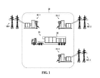
60 to the docking
station 55-2. During the transportation of the energy storage unit 60, the
battery
cells are to be maintained in an operational state as shown in block 670. Upon
arriving at the docking station 55-2 connected to the power distribution
network 100-
2, the energy storage unit 60 is to be connected and provide energy in a
similar
manner as described in blocks 630 to 650. It is to be appreciated by a person
of skill
with the benefit of this description that although the above example describes
moving the energy storage unit 60 from the docking station 55-1 to the docking
station 55-2, that the energy storage unit may be moved between any docking
station 55 to provide energy to different power distribution networks 100.
17
CA 03208748 2023-8- 16
WO 2022/178004
PCT/US2022/016618
Furthermore, while the energy storage unit 60 is connected to a power
distribution
network 100, the energy storage unit 60 may be charged in periods of low power
consumption. Accordingly, the energy storage unit 60 may be generally in a
charged
state such that when the energy storage unit 60 is to be relocated, the energy
storage unit 60 may be connected to the new power distribution network 100
without
charging prior to use.
[0062] Various advantages will now become apparent to a person
of skill with the
benefit of this description. In particular, the system 50 provides for a quick
connection and disconnection from a utility grid through a process that may
typically
that does not involve taking the energy storage unit 60 out of the fully
assembled
state during the disconnection process and re-racking the energy storage unit
60 to
be used at a new location. The allows for users to utilize the benefits of an
energy
storage platform during a defined period of time, such as 100-200 hours per
year,
when energy storage may be beneficial to costs or to supplement electricity
generation during peak demand periods. During periods when the energy storage
unit 60 is not used, the energy storage unit 60 may be easily relocated to
another
location, such as for another user. Accordingly, capital expenditures,
insurance,
electrical carrying costs, and maintenance may be shared by multiple users.
[0063] It should be recognized that features and aspects of the
various examples
provided above may be combined into further examples that also fall within the
scope of the present disclosure.
18
CA 03208748 2023-8- 16