Note: Descriptions are shown in the official language in which they were submitted.
DIELECTRIC COATINGS
CROSS-REFERENCE TO RELATED APPLICATIONS
[0001] This application claims priority to PCT Application No.
PCT/CN2022/113045,
filed on August 17, 2022, entitled "Dielectric Coatings," incorporated herein
by reference in its
entirety.
FIELD
[0002] The present disclosure is directed towards dielectric coatings,
systems for coating
substrates, methods for coating substrates, and coated substrates.
BACKGROUND
[0003] Coatings, including those formed from powder coating compositions,
and
adhesives are utilized in a wide variety of applications, including use as
interface materials to
manage structural integrity and thermal management in heat transfer systems.
SUMMARY
[0004] Disclosed herein are coated substrates comprising a coating layer
and an adhesive
formed on at least a portion of the coating layer, wherein the coating layer
is deposited from a
powder coating composition and comprises a dielectric strength of at least 50
kV/rnm measured
according to ASTM D149-09 (voltage limit 12.0 kV DC, Imax Limit 0.1 mA, 19 sec
ramp, 20
sec dwell, 2 sec fall), such as at least 60 kV/mm, such as no more than 120
kV/min, such as no
more than 100 kV/mm, such as 50 kV/mm to 120 kV/mm, such as 60 kV/mm to 100
kV/mm,
and a thermal conductivity of at least 0.3 W/K m measured according to ASTM
D5470 (steady-
state methods), such as at least 0.35 W/K.m, such as no more than 0.5 W/K.m,
such as no more
than 0.45 W/K.m, such as 0.3 W/K.m to 0.5 W/K.m, such as 0.35 W/K.m to 0.45
W/K.m, and
wherein the adhesive is fon-ned from an adhesive composition and comprises a
thermal
conductivity of at least 0.7 W/K m measured according to ASTM D5470, such as
at least 0.8
W/K.m, such as at least 0.9 W/K.m, such as at least 1.0 W/K.m, such as at
least 1.5 W/K.m, such
as no more than 2.5 W/K.m, such as no more than 2.0 W/K.m, such as 0.7 W/K.m
to 2.5 W/K.m,
such as 0.8 W/K.m to 2.5 W/K.m, such as 0.9 W/K.m to 2.5 W/K.m, such as 1.0
W/K m to 2.5
W/K-m, such as 1.5 W/K.m to 2.5 W/K.m, such as 0.7 W/K.m to 2.0 W/K.m, such as
0.8 W/K.m
to 2.0 W/K.m, such as 0.9 W/K.m to 2.0 W/K.m, such as 1.0 W/K m to 2.0 W/K-m,
such as 1.5
W/K.m to 2.0 W/K.m.
- 1 -
Date Recue/Date Received 2023-08-15
[0005] Also disclosed herein are systems for coating substrates comprising
a powder
coating composition comprising an electrically insulative filler and an
adhesive coating
composition comprising a thermally conductive filler, wherein the two layers,
when deposited on
a substrate and cured, have a thermal resistance of no more than 2.0 C/W as
measured using a
TIM Thermal Resistance and Conductivity Measurement Apparatus (model LW-9389)
in
accordance with ASTM D5470 (steady-state method), such as 0.5 C/VV to 2.0
C/VV.
[0006] Also disclosed are methods of coating a substrate comprising
applying a powder
composition onto a surface of the substrate to form a coating and applying an
adhesive
composition to at least a portion of the coating to form an adhesive.
BRIEF DESCRIPTION OF THE DRAWINGS
[0007] FIG. 1 is a schematic of a top-down view of cylindrical battery
cells.
[0008] FIG. 2 is a schematic of an exploded isometric view of an array of
prismatic
battery cells.
[0009] FIG. 3 is a schematic of a front view of an array of pouch battery
cells.
[0010] FIG. 4 is a schematic of an isometric view of cylindrical cells
positioned in a
battery module.
[0011] FIG. 5 is a schematic of an exploded perspective view of a battery
pack
comprising multiple battery cells.
[0012] FIG. 6 is a schematic of an isometric view of (A) a battery cell,
(B) a battery
module, and (C) a battery pack.
[0013] FIG. 7 is a schematic of a perspective view of a battery pack.
[0014] FIG. 8 is a schematic of a cell to battery pack configuration.
[0015] FIG. 9 is a schematic of an isometric cut-out view of a cell to
chassis battery
assembly.
DETAILED DESCRIPTION
[0016] For purposes of this detailed description, it is to be understood
that the present
disclosure may assume alternative variations and step sequences, except where
expressly
specified to the contrary. Moreover, other than in any operating examples, or
where otherwise
indicated, all numbers expressing, for example, quantities of ingredients used
in the specification
and claims are to be understood as being modified in all instances by the term
"about".
Accordingly, unless indicated to the contrary, the numerical parameters set
forth in the following
- 2 -
Date Recue/Date Received 2023-08-15
specification and attached claims are approximations that may vary depending
upon the desired
properties to be obtained by the present disclosure. At the very least, and
not as an attempt to
limit the application of the doctrine of equivalents to the scope of the
claims, each numerical
parameter should at least be construed in light of the number of reported
significant digits and by
applying ordinary rounding techniques.
[0017] Notwithstanding that the numerical ranges and parameters setting
forth the broad
scope of the present disclosure are approximations, the numerical values set
forth in the specific
examples are reported as precisely as possible. Any numerical value, however,
inherently
contains certain errors necessarily resulting from the standard variation
found in their respective
testing measurements.
[0018] Also, it should be understood that any numerical range recited
herein is intended
to include all sub-ranges subsumed therein. For example, a range of "1 to 10"
is intended to
include all sub-ranges between (and including) the recited minimum value of 1
and the recited
maximum value of 10, that is, having a minimum value equal to or greater than
1 and a
maximum value of equal to or less than 10.
[0019] As used herein, "including," "containing" and like terms are
understood in the
context of this application to be synonymous with "comprising" and are
therefore open-ended
and do not exclude the presence of additional undescribed or unrecited
elements, materials,
ingredients or method steps.
[0020] As used herein, "consisting of" is understood in the context of
this application to
exclude the presence of any unspecified element, ingredient or method step.
[0021] As used herein, "consisting essentially of' is understood in the
context of this
application to include the specified elements, materials, ingredients or
method steps "and those
that do not materially affect the basic and novel characteristic(s)" of what
is being described. As
used herein, open-ended terms include closed terms such as "consisting
essentially" of and
"consisting of."
[0022] In this application, the use of the singular includes the plural
and plural
encompasses singular, unless specifically stated otherwise. For example,
although reference is
made herein to "a" coating or "an" filler material, a combination (i.e., a
plurality) of these
components may be used.
- 3 -
Date Recue/Date Received 2023-08-15
[0023] In addition, in this application, the use of "or" means "and/or"
unless specifically
stated otherwise, even though "and/or" may be explicitly used in certain
instances.
[0024] As used herein, the terms "on," "onto," "applied on," "applied
onto," "formed
on," "deposited on," "deposited onto," and the like mean formed, overlaid,
deposited, or
provided on, but not necessarily in contact with, a substrate surface. For
example, a composition
"applied onto" a substrate surface does not preclude the presence of one or
more other
intervening coating layers or films of the same or different composition
located between the
composition and the substrate surface.
[0025] As used herein, a "coating composition" refers to a composition,
e.g., a mixture or
a dispersion, that is capable of producing a film, layer, or the like on at
least a portion of a
substrate surface.
[0026] As used herein, a "powder coating composition" refers to a coating
composition embodied in solid particulate form as opposed to liquid form.
[0027] As used herein, the term "adhesive" means an adhesive producing a
load-bearing
joint having a lap shear strength of greater than 3.0 MPa, measured according
to ASTM D1002-
using 2024-T3 aluminum substrate of 1.6 mm thickness, as measured by an
INSTRON 5567
machine in tensile mode with a pull rate of 1.3 mm per minute.
[0028] As defined herein, a "1K" or "one-component" coating composition,
is a
composition in which all of the ingredients may be premixed and stored and
wherein the reactive
components do not readily react at ambient or slightly thermal conditions, but
instead only react
upon activation by an external energy source. In the absence of activation
from the external
energy source, the composition will remain largely unreacted (maintaining
sufficient workability
in the uncured state and greater than 70% of the initial lap shear strength of
the composition in
the cured state after storage at 25 C for 8 months). External energy sources
that may be used to
promote the curing reaction (i.e., the crosslinking of the epoxy component and
the curing agent)
include, for example, radiation (i.e., actinic radiation) and/or heat.
[0029] "Ambient" conditions generally refer to room temperature and
humidity
conditions and may be 10 C to 32 C and 20% relative humidity to 80% relative
humidity, while
slightly thermal conditions are slightly above ambient temperature (e.g., 32 C
to 35 C) but, in the
case of a 1K composition, generally are below the curing temperature for the
coating
- 4 -
Date Recue/Date Received 2023-08-15
composition, i.e., are generally below those at which the reactive components
will readily react
and cure.
[0030] As used herein, the term "two-component" or "2K" refers to a
composition in
which at least a portion of the reactive components readily associate to form
an interaction or
react to form a bond (physically or chemically), and at least partially cure
without activation
from an external energy source, such as at ambient or slightly thermal
conditions, when mixed.
One of skill in the art understands that the two components of the composition
are stored
separately from each other and mixed just prior to application of the
composition. Two-
component compositions may optionally be heated or baked, as described below.
[0031] As used herein, the term "cure" or "curing", means that the
components that form
the composition are crosslinked to form a material, such as a coating, a
layer, pottant, pad or the
like. As used herein, the term "at least partially cured" means that at least
a portion of the
components that form the composition interact, react, and/or are crosslinked
to form the material.
The composition is at least partially cured or cured when the components of
the composition are
mixed, resulting in at least a partial reaction of the reactive functional
groups of the components
of the composition.
[0032] The term "curable", as used for example in connection with a
curable
composition, means that the indicated composition is polymerizable or cross
linkable through
functional groups, e.g., by means that include, but are not limited to, cure
under ambient or
slightly thermal conditions and/or catalytic exposure.
[0033] "Curable under ambient conditions" means that the composition
undergoes a
thermosetting reaction at room temperature and humidity conditions, e.g.,
without the aid of heat
or other energy, for example, without baking in an oven, use of forced air, or
the like.
[0034] As used herein, unless indicated otherwise, the term
"substantially free" means
that a particular material is not purposefully added to a mixture or
composition, respectively, and
is only present as an impurity in a trace amount of less than 5% by weight
based on a total
weight of the mixture or composition, respectively. As used herein, unless
indicated otherwise,
the term "essentially free" means that a particular material is only present
in an amount of less
than 2% by weight based on a total weight of the mixture or composition,
respectively. As used
herein, unless indicated otherwise, the term "completely free" means that a
mixture or
- 5 -
Date Recue/Date Received 2023-08-15
composition, respectively, does not comprise a particular material, i.e., the
mixture or
composition comprises 0% by weight of such material.
Coatings and Coated Substrates
[0035] Disclosed herein are coated substrates comprising a coating layer
and an adhesive
formed on at least a portion of the coating layer. As described in more detail
below, the coating
layer may be deposited from a powder coating composition and the adhesive may
be deposited
from an adhesive composition.
[0036] The coating layer may comprise a dielectric strength of at least 50
kV/mm
measured using a Sefelec Dielectric Strength Tester (RMG12AC-DC; voltage limit
12.0 kV DC,
Imax Limit 0.1 mA, 19 sec ramp, 20 sec dwell, 2 sec fall) according to ASTM
D149-09, such as
at least 60 kV/mm. The coating layer may comprise a dielectric strength of no
more than 120
kV/mm measured using a Sefelec Dielectric Strength Tester (RMG12AC-DC; voltage
limit 12.0
kV DC, Imax Limit 0.1 mA, 19 sec ramp, 20 sec dwell, 2 sec fall) according to
ASTM D149-09,
such as no more than 100 kV/mm. The coating layer may comprise a dielectric
strength of 50
kV/mm to 120 kV/mm measured using a Sefelec Dielectric Strength Tester
(RMG12AC-DC;
voltage limit 12.0 kV DC, Imax Limit 0.1 mA, 19 sec ramp, 20 sec dwell, 2 sec
fall) according to
ASTM D149-09, such as 60 kV/mm to 100 kV/min.
[0037] The coating layer may comprise a thermal conductivity of at least
0.3 W/K-m
measured using a TIM Thermal Resistance and Conductivity Measurement Apparatus
(model
LW-9389) according to ASTM D5470 (steady-state methods), such as at least 0.35
W/K m. The
coating layer may comprise a thermal conductivity of no more than 0.5 W/K m
measured using a
TIM Thermal Resistance and Conductivity Measurement Apparatus (model LW-9389)
according
to ASTM D5470 (steady-state methods), such as no more than 0.45 W/K-m. The
coating layer
may comprise a thermal conductivity of 0.3 W/Km to 0.5 W/K-m measured using a
TIM
Thermal Resistance and Conductivity Measurement Apparatus (model LW-9389)
according to
ASTM D5470 (steady-state methods), such as 0.35 W/K m to 0.45 W/K m.
[0038] The coating layer may comprise a dielectric breakdown of at least
12 kV/mm
measured using a Sefelec Dielectric Strength Tester (RMG12AC-DC; voltage limit
12.0 kV DC,
Imax Limit 0.1 mA, 19 sec ramp, 20 sec dwell, 2 sec fall) according to ASTM
D149-09, such as
at least 15 kV/mm, such as at least 20 kV/mm, such as at least 25 kV/mm, such
as at least 30
kV/min.
- 6 -
Date Recue/Date Received 2023-08-15
[0039] The powder coating compositions can be applied by any means
standard in the
art, such as spraying, electrostatic spraying, a fluidized bed process, and
the like. The powder
coating compositions can also be applied in multiple applications over a
substrate (a "multi-
application process"). For instance, a first powder coating composition can be
applied over at
least a portion of a substrate. A second powder coating composition can be
applied over at least
a portion of the first coating composition. The first powder coating
composition can optionally
be cured or at least partially cured before applying the second powder coating
composition.
Alternatively, the second powder coating composition can be applied over at
least a portion of
the first coating composition. The first and second powder coating composition
can then be
cured together at the same time.
[0040] It is appreciated that the powder coating composition can be cured
with multiple
types of heat sources such as both convection heating and infrared radiation.
For example, the
powder coating composition can be partially cured with convection heating or
infrared radiation,
and then completely cured with a different heat source chosen from convection
heating and
infrared radiation.
[0041] In some examples, the powder coating composition can be cured with
heat, such
convection heating within a range of 120 C to 260 C, such as 160 C to 240
C, such as 180 C
to 200 C, for 1 minute to 40 minutes. The powder coating composition can also
be cured with
infrared radiation in which peak metal temperatures can reach 200 C to 260 C
in about 10
seconds. The elevated heat ramping with infrared radiation allows for fast
cure times. In some
examples, the powder coating composition is cured with infrared radiation to
heat the
composition within a range of from 140 C to 180 C for 1 to 20 minutes.
[0042] Coatings formed from a single powder coating composition can be
applied at any
desired dry film thickness. For example, the dry film thickness may be at
least 50 microns, such
as at least 75 microns, such as at least 100 microns, For example, the dry
film thickness may be
no more than 300 microns, such as no more than 250 microns, such as no more
than 200
microns. The dry film thickness may be 50 microns to 300 microns, such as 75
microns to 250
microns, such as 100 microns to 200 microns, such as 100 microns to 220
microns. It is
appreciated that, when multiple powder coating compositions are applied, each
composition can
be applied to separately provide any of the previously described dry film
thicknesses. For
- 7 -
Date Recue/Date Received 2023-08-15
instance, when two separate powder coating compositions are applied, each
individual powder
coating composition can be applied at any of the previously described dry film
thicknesses.
[0043] The adhesive may comprise a thermal conductivity of at least 0.7
W/K m
measured using a TIM Thermal Resistance and Conductivity Measurement Apparatus
(model
LW-9389) according to ASTM D5470 (steady-state methods), such as at least 0.8
W/K.m, such
as at least 0.9 W/K.m, such as at least 1.0 W/K.m, such as at least 1.5 W/K m.
The coating layer
may comprise a thermal conductivity of no more than 2.5 W/K m measured using a
TIM
Thermal Resistance and Conductivity Measurement Apparatus (model LW-9389)
according to
ASTM D5470 (steady-state methods), such as no more than 2.0 W/K m. The coating
layer may
comprise a thermal conductivity of 0.7 W/K m to 2.5 W/Km measured using a TIM
Thermal
Resistance and Conductivity Measurement Apparatus (model LW-9389) according to
ASTM
D5470 (steady-state methods), such as 0.8 W/K-m to 2.5 W/K-m, such as 0.9
W/K.m to 2.5
W/K.m, such as 1.0 W/K.m to 2.5 W/K.m, such as 1.5 to 2.5 W/K.m, such as 0.7
W/K.m to 2.0
W/K.m such as 0.8 W/K m to 2.0 W/K m, such as 0.9 W/K.m to 2.0 W/K.m, such as
1.0 W/K.m
to 2.0 W/K.m, such as 1.5 to 2.0 W/K.m,
[0044] The adhesive may comprise a dielectric breakdown of at least 6
kV/mm measured
using a Sefelec Dielectric Strength Tester (RMG12AC-DC; voltage limit 12.0 kV
DC, Imax
Limit 0.1 mA, 19 sec ramp, 20 sec dwell, 2 sec fall) according to ASTM D149-
09, such as at
least 6 kV/mm. The adhesive may comprise a dielectric breakdown of no more
than 20 kV/mm
measured using a Sefelec Dielectric Strength Tester (RMG12AC-DC; voltage limit
12.0 kV DC,
Imax Limit 0.1 mA, 19 sec ramp, 20 sec dwell, 2 sec fall) according to ASTM
D149-09, such as
no more than 17 kV/mm. The adhesive may comprise a dielectric breakdown of 6
kV/mm to 20
kV/mm measured using a Sefelec Dielectric Strength Tester (RMG12AC-DC; voltage
limit 12.0
kV DC, Imax Limit 0.1 mA, 19 sec ramp, 20 sec dwell, 2 sec fall) according to
ASTM D149-09,
such as 10 kV/mm to 17 kV/mm.
[0045] The adhesive may comprise a lap shear strength of at least 3 MPa
measured
according to ASTM D1002-10 using an Instron 5567 machine in tensile mode with
a pull rate of
1 mm per minute, such as at least 8 MPa. The adhesive may comprise a lap shear
strength of no
more than 30 MPa measured according to ASTM D1002-10 using an Instron 5567
machine in
tensile mode with a pull rate of 1 mm per minute, such as no more than 12 MPa.
The adhesive
may comprise a lap shear strength of 3 MPa to 30 MPa measured according to
ASTM D1002-10
- 8 -
Date Recue/Date Received 2023-08-15
using an Instron 5567 machine in tensile mode with a pull rate of 1 mm per
minute, such as 8
MPa to 12 MPa.
[0046] The adhesive compositions may be applied by any means standard in
the art, such
as brushes, rollers, films, pellets, trowels, spatulas, dips, spray guns and
applicator guns to form a
coating on at least a portion of the coating described above. An adhesive is
typically formed
when a composition that is deposited onto at least a portion of the substrate
surface is at least
partially dried or cured by methods known to those of ordinary skill in the
art (e.g., under
ambient conditions or by exposure to thermal heating).
[0047] For example, the adhesive composition may be allowed to cure at
room
temperature or slightly thermal conditions and/or the composition may be cured
by baking and/or
curing at elevated temperature, such as at a temperature of 180 C or below,
such as 130 C or
below, such as 110 C or below, such as 100 C or below, such as 90 C or below,
such as 80 C or
below, such as 70 C or below, but greater than ambient, such as greater than
40 C, such as
greater than 50 C, and for any desired time period (e.g., from 5 minutes to 1
hour) sufficient to at
least partially cure the composition on the substrate(s). Alternatively, the
adhesive composition
may cure at ambient or slightly above ambient conditions and optionally may be
baked and/or
further cured at elevated temperatures, such as those described above.
[0048] The adhesives formed from an adhesive composition can be applied at
any desired
dry film thickness. For example, the dry film thickness may be at least 0.2
mm, such as at least
0.3 mm, such as at least 0.4 mm. The dry film thickness may be no more than
3.0 mm, such as
no more than 1.5 mm, such as no more than 1.0 mm. The dry film thickness may
be 0.2 mm to
3.0 mm, such as 0.3 mm to 1.5 mm, such as 0.4 mm to 1.0 mm. .
Systems
[0049] Also disclosed herein are systems for coating a substrate
comprising a powder
coating composition and an adhesive composition. As described in more detail
below, the
powder coating composition may comprise an electrically insulative filler and
the adhesive
composition may comprise a thermally conductive filler.
Powder Coating Compositions
[0050] The coating may be deposited from a powder coating composition
comprising, or
consisting essentially of, or consisting of: an electrically insulative
filler; and a (meth)acrylate
- 9 -
Date Recue/Date Received 2023-08-15
resin, a polyurethane, a polyester, a polyamide, a polyether, a polysiloxane,
an epoxy resin, a
vinyl resin, copolymers thereof, and/or combinations thereof.
[0051] The powder coating composition comprises a binder. The binder
comprises one
or more film-forming resins that can be used to form the coating layer. The
powder coating
compositions include any of a variety of thermosetting powder coating
compositions known in
the art. The powder coating compositions can also include thermoplastic powder
coating
compositions.
[0052] Non-limiting examples of suitable film-forming resins that form at
least a portion
of the binder of the powder coating composition include (meth)acrylate resins,
polyurethanes,
polyesters, polyamides, polyethers, polysiloxanes, epoxy resins, vinyl resins,
copolymers thereof,
and combinations thereof. As used herein, "(meth)acrylate" and like terms
refers both to the
acrylate and the corresponding methacrylate. Further, the film-forming resins
can have any of a
variety of functional groups including, but not limited to, carboxylic acid
groups, amine groups,
epoxide groups, hydroxyl groups, thiol groups, carbamate groups, amide groups,
urea groups,
isocyanate groups (including blocked isocyanate groups), ethylenically
unsaturated groups, and
combinations thereof.
[0053] Thermosetting coating compositions typically comprise a
crosslinker that may be
selected from any of the crosslinkers known in the art to react with the
functionality of one or
more film-forming resins used in the powder coating composition. Non-limiting
examples of
crosslinkers include phenolic resins, amino resins, epoxy resins, triglycidyl
isocyanurate, beta-
hydroxy (alkyl) amides, alkylated carbamates, (meth)acrylates, salts of poly
carboxylic acids
with cyclic amidine, o-tolyl biguanide, isocyanates, blocked isocyanates,
polyacids, anhydrides,
organometallic acid-functional materials, polyamines, polyamides, aminoplasts,
carbodiimides,
oxazolines, and combinations thereof.
[0054] Suitable examples of resins useful in the powder coating
compositions are
discussed in PCT Publ. No. WO 2021/173941A1, pars. [0006] to [0042], [0057] to
[0068],
[0088] to [0105] and [0128] to [0139], incorporated herein by reference.
[0055] The electrically insulative filler may be thermally conductive
filler or non-
thermally conductive filler. As used herein, the term "electrically insulative
filler" means a
pigment, filler, or inorganic powder that has a volume resistivity of at least
10 am (measured
according to ASTM D257, C611, or B193). For example, the electrically
insulative filler may
- 10 -
Date Recue/Date Received 2023-08-15
have a volume resistivity of at least 10 am (measured according to ASTM D257,
C611, or
B193), such as at least 20 fl-m, such as at least 30 fl-m, such as at least 40
am, such as at least
50 am, such as at least 60 am, such as at least 60 am, such as at least 70
fl.m, such as at least
80 am, such as at least 80 am, such as at least 90 am, such as at least 100
am.
[0056] The electrically insulative filler may comprise a thermally
conductive, electrically
insulative filler material. As used herein, the term "thermally conductive,
electrically insulative
filler" or "TC/EI filler" means a pigment, filler, or inorganic powder that
has a thermal
conductivity of at least 5 W/m-K at 25 C (measured according to ASTM D7984)
and a volume
resistivity of at least 10 am (measured according to ASTM D257, C611, or
B193). The TC/EI
filler material may comprise organic or inorganic material and may comprise
particles of a single
type of filler material or may comprise particles of two or more types of
TC/EI filler materials.
That is, the TC/EI filler material may comprise particles of a first TC/EI
filler material and may
further comprise particles of at least a second (i.e., a second, a third, a
fourth, etc.) TC/EI filler
material that is different from the first TC/EI filler material. As used
herein with respect to types
of filler material, reference to "first," "second", etc. is for convenience
only and does not refer to
order of addition or the like.
[0057] The TC/EI filler material may have a thermal conductivity of at
least 5 W/m-K at
25 C (measured according to ASTM D7984), such as at least 18 W/m-K, such as at
least 55
W/m K. The TC/EI filler material may have a thermal conductivity of no more
than 3,000
WirruK at 25 C (measured according to ASTM D7984), such as no more than 1,400
W/m-K, such
as no more than 450 W/m K. The TC/EI filler material may have a thermal
conductivity of 5
W/m-K to 3,000 W/m K at 25 C (measured according to ASTM D7984), such as 18
W/m-K to
1,400 W/m K, such as 55 W/m-K to 450 W/m K.
[0058] The TC/EI filler material may have a volume resistivity of at least
10 am
(measured according to ASTM D257, C611, or B193), such as at least 20 am, such
as at least
30 fl-m, such as at least 40 fl-m, such as at least 50 am, such as at least 60
am, such as at least
60 am, such as at least 70 am, such as at least 80 am, such as at least 80 am,
such as at least
90 am, such as at least 100 am.
[0059] Suitable non-limiting examples of TC/EI filler materials include
nitrides, metal
oxides, metalloid oxides, metal hydroxides, arsenides, carbides, minerals,
ceramics, and
diamond. For example, the TC/EI filler material may comprise, consist
essentially of, or consist
- 11 -
Date Recue/Date Received 2023-08-15
of boron nitride, silicon nitride, aluminum nitride, boron arsenide, aluminum
oxide, magnesium
oxide, dead burned magnesium oxide, beryllium oxide, silicon dioxide, titanium
oxide, zinc
oxide, nickel oxide, copper oxide, tin oxide, aluminum hydroxide (i.e.,
aluminum trihydrate),
magnesium hydroxide, boron arsenide, silicon carbide, agate, emery, ceramic
microspheres,
diamond, or any combination thereof. Non-limiting examples of commercially
available TC/EI
filler materials of boron nitride include, for example, CarboTherm from Saint-
Gobain, CoolFlow
and PolarThenu from Momentive, and as hexagonal boron nitride powder available
from
Panadyne; of aluminum nitride, for example, aluminum nitride powder available
from Micron
Metals Inc., and as Toyalnite from Toyal; of aluminum oxide include, for
example, Microgrit
from Micro Abrasives, Nabalox from Nabaltec, Aeroxide from Evonik, and as
Alodur from
Imerys; of dead burned magnesium oxide include, for example, MagChem P98 from
Martin
Marietta Magnesia Specialties; of aluminum hydroxide include, for example,
APYRAL from
Nabaltec GmbH and aluminum hydroxide from Sibelco; and of ceramic microspheres
include,
for example, ceramic microspheres from Zeeospheres Ceramics or 3M. These
fillers can also be
surface modified. For example, surface modified magnesium oxide available as
PYROKISUMA
5301K available from Kyowa Chemical Industry Co., Ltd. Alternatively, the
TC/EI filler
materials may be free of any surface modification.
[0060] As used herein, the term "dead burned magnesium oxide" refers to
magnesium
oxide that has been calcined at high-temperatures (e.g., ranging from 1500 C ¨
2000 C in a high
temperature shaft kiln) yielding a material with very little reactivity
relative to magnesium oxide
that has not been calcined.
[0061] The TC/EI filler material may be included as a single TC/EI filler
material or may
be included as a combination of two or more of the TC/EI filler materials
described above.
[0062] The electrically insulative filler may comprise a non-thermally
conductive,
electrically insulative filler material. As used herein, the term "non-
thermally conductive,
electrically insulative filler" or "NTC/EI filler" means a pigment, filler, or
inorganic powder that
that has a thermal conductivity of less than 5 W/mK at 25 C (measured
according to ASTM
D7984) and a volume resistivity of at least 10 am (measured according to ASTM
D257, C611,
or B193). For example, the NTC/EI filler may have a thermal conductivity of
less than 5 W/mK
at 25 C (measured according to ASTM D7984, such no more than 3 W/mK, such as
no more
than 1 W/mK, such as no more than 0.1 W/mK, such as no more than 0.05 W/mK.
For example,
- 12 -
Date Recue/Date Received 2023-08-15
the NTC/EI filler may have a volume resistivity of at least 10 am (measured
according to
ASTM D257, C611, or B193), such as at least 20 fl-m, such as at least 30 am,
such as at least
40 am, such as at least 50 am, such as at least 60 am, such as at least 60
fl.m, such as at least
70 am, such as at least 80 am, such as at least 80 am, such as at least 90 am,
such as at least
100 fl-m. The NTC/EI filler material may be organic or inorganic.
[0063] Suitable non-limiting examples of NTC/EI filler materials include
but are not
limited to mica, silica, wollastonite, barium sulfate, calcium carbonate,
glass microspheres, clay,
or any combination thereof.
[0064] As used herein, the term "mica" generally refers to sheet silicate
(phyllosilicate)
minerals. The mica may comprise muscovite mica. Muscovite mica comprises a
phyllosilicate
mineral of aluminum and potassium with the formula KAl2(AlSi3010)(F,OH)2 or
(KF)2(A1203)3(Si02)6(H20). Exemplary non-limiting commercially available
muscovite mica
include products sold under the trade name DakotaPURETM, such as DakotaPURETM
700,
DakotaPURETM 1500, DakotaPURETM 2400, DakotaPURETM 3000, DakotaPURETM 3500 and
DakotaPURETM 4000, available from Pacer Minerals.
[0065] The silica (SiO2) may comprise fumed silica which comprises silica
that has been
treated with a flame to form a three-dimensional structure. The fumed silica
may be untreated or
surface treated with a siloxane, such as, for example, polydimethylsiloxane.
Exemplary non-
limiting commercially available fumed silica includes products solder under
the trade name
AEROSIL , such as AEROSIL R 104, AEROSIL R 106, AEROSIL R 202, AEROSIL R
208, AEROSIL R 972 commercially available from Evonik Industries and products
sold under
the trade name HDK such as HDK H17 and HDK H18 commercially available from
Wacker Chemie AG.
[0066] Wollastonite comprises a calcium inosilicate mineral (CaSiO3) that
may contain
small amounts of iron, aluminum, magnesium, manganese, titanium and/or
potassium. For
example, the wollastonite may have a B.E.T. surface area of 1.5 to 2.1 m2/g,
such as 1.8 m2/g and
a median particle size of 6 microns to 10 microns, such as 8 microns. Non-
limiting examples of
commercially available wollastonite include NYAD 400 available from NYCO
Minerals, Inc.
[0067] The calcium carbonate (CaCO3) may comprise a precipitated calcium
carbonate
or a ground calcium carbonate. The calcium carbonate may or may not be surface
treated with
stearic acid. Non-limiting examples of commercially available precipitated
calcium carbonate
- 13 -
Date Recue/Date Received 2023-08-15
include Ultra-Pflex , Albafil , and Albacar HO available from Specialty
Minerals and
Winnofil SPT available from Solvay. Non-limiting examples of commercially
available
ground calcium carbonate include DuramiteTM available from IMERYS and
Marblewhite
available from Specialty Minerals.
[0068] Useful clay minerals include a non-ionic platy filler such as talc,
pyrophyllite,
chlorite, vermiculite, or combinations thereof.
[0069] The glass microspheres may be hollow borosilicate glass. Non-
limiting examples
of commercially available glass microspheres include 3M Glass bubbles type VS,
K series, and S
series available from 3M.
[0070] The electrically insulative filler material may have any particle
shape or
geometry. For example, the electrically insulative filler material may be a
regular or irregular
shape and may be spherical, ellipsoidal, cubical, platy, acicular (elongated
or fibrous), rod-
shaped, disk-shaped, prism-shaped, flake-shaped, rock-like, etc., agglomerates
thereof, and any
combination thereof.
[0071] Particles of electrically insulative filler material may have a
reported average
particle size in at least one dimension of at least 0.01 microns, as reported
by the manufacturer,
such as at least 2 microns, such as at least 10 microns. Particles of
electrically insulative filler
material may have a reported average particle size in at least one dimension
of no more than 500
microns as reported by the manufacturer, such as no more than 300 microns,
such as no more
than 200 microns, such as no more than 150 microns. The particles of
electrically insulative
filler material may have a reported average particle size in at least one
dimension of 0.01
microns to 500 microns as reported by the manufacturer, such as 0.1 microns to
300 microns,
such as 2 microns to 200 microns, such as 10 microns to 150 microns. Suitable
methods of
measuring average particle size include measurement using an instrument such
as the Quanta
250 FEG SEM or an equivalent instrument.
[0072] Particles of electrically insulative filler material of the powder
coating
composition may have a reported Mohs hardness of at least 1 (based on the Mohs
Hardness
Scale), such as at least 2, such as at least 3. Particles of electrically
insulative filler material of
the powder coating composition may have a reported Mohs hardness of no more
than 10, such as
no more than 8, such as no more than 7. Particles of electrically insulative
filler material of the
- 14 -
Date Recue/Date Received 2023-08-15
powder coating composition may have a reported Mohs hardness of 1 to 10, such
as 2 to 8, such
as 3 to 7.
[0073] The powder coating composition may comprise the electrically
insulative filler
material in an amount of at least 30 percent by weight based on total weight
of the powder
coating composition, such as at least 45 percent by weight, such as at least
50 percent by weight.
The powder coating composition may comprise the electrically insulative filler
material in an
amount of no more than 60 percent by weight based on total weight of the
powder coating
composition, such as no more than 55 percent by weight, such as no more than
50 percent by
weight. The powder coating composition may comprise the electrically
insulative filler material
in an amount of 30 percent by weight to 60 percent by weight based on total
weight of the
powder coating composition, such as 45 percent by weight to 55 percent by
weight, such as 45
percent by weight to 50 percent by weight, such as 50 percent by weight to 55
percent by weight.
[0074] Powder coating compositions can comprise a flame retardant or
combination of
flame retardants. Certain TC materials described above such as aluminum
hydroxide and
magnesium hydroxide, for example, also may be flame retardants. As used
herein, "flame
retardant" refers to a material that slows down or stops the spread of fire or
reduces its intensity.
Flame retardants may be available as a powder that may be mixed with a
composition, a foam, or
a gel. In examples, when the powder coating compositions include a flame
retardant, such
compositions may form a coating on a substrate surface and such coating may
function as a
flame retardant.
[0075] As set forth in more detail below, a flame retardant can include a
mineral, an
organic compound, an organohalogen compound, an organophosphorous compound, or
a
combination thereof. Suitable examples of minerals include huntite,
hydromagnesite, various
hydrates, red phosphorous, boron compounds such as borates, carbonates such as
calcium
carbonate and magnesium carbonate, and combinations thereof. Suitable examples
of
organohalogen compounds include organochlorines such as chlorendic acid
derivatives
and chlorinated paraffins; organobromines such as decabromodiphenyl ether
(decaBDE),
decabromodiphenyl ethane (a replacement for decaBDE), polymeric brominated
compounds
such as brominated polystyrenes, brominated carbonate oligomers (BC0s),
brominated epoxy
oligomers (BE0s), tetrabromophthalic anyhydride, tetrabromobisphenol A (TBBPA)
and hexabromocyclododecane (HBCD). Such halogenated flame retardants may be
used in
- 15 -
Date Recue/Date Received 2023-08-15
conjunction with a synergist to enhance their efficiency. Other suitable
examples include
antimony trioxide, antimony pentaoxide, and sodium antimonate. Suitable
examples of
organophosphorous compounds include triphenyl phosphate (TPP), resorcinol
bis(diphenylphosphate) (RDP), bisphenol A diphenyl phosphate (BADP), and
tricresyl
phosphate (TCP); phosphonates such as dimethyl methylphosphonate (DMMP);
and phosphinates such as aluminum diethyl phosphinate. In one important class
of flame
retardants, compounds contain both phosphorus and a halogen. Such compounds
include tris(2,3-
dibromopropyl) phosphate (brominated tris) and chlorinated organophosphates
such as tris(1,3-
dichloro-2-propyl)phosphate (chlorinated tris or TDCPP) and tetrakis(2-
chlorethyl)dichloroisopentyldiphosphate (V6). Suitable examples of organic
compounds include
carboxylic acid, dicarboxylic acid, melamine, and organonitrogen compounds.
Other suitable
flame retardants include ammonium polyphosphate and barium sulfate.
Adhesive Compositions
[0076] The adhesive may be deposited from an adhesive composition
comprising, or
consisting essentially of, or consisting of: a thermally conductive filler;
and a compound
comprising an electrophilic functional group, a thiol-terminated compound, a
thermoplastic
polymer or any combination thereof.
[0077] The adhesive composition may be a one-component adhesive
composition, a two-
component composition, or a multi-component composition (i.e., more than two
components).
[0078] Suitable electrophilic functional groups useful in the adhesive
compositions
disclosed herein include epoxide functional groups, carbonate functional
groups, isocyanate
functional groups, keto functional groups, aziridine functional groups,
thiirane functional groups,
cyclic lactone functional groups, and carbodiimide functional groups. The
adhesive composition
may further comprise a second compound comprising a nucleophilic functional
group. The
second molecule may be monofunctional or polyfunctional. The second molecule
may be a
monomer, a small molecule, or a polymer. Suitable nucleophilic functional
groups include active
hydrogen functional groups including amine functional groups, hydroxy
functional groups, thiol
functional groups, carboxy functional groups, anhydride functional groups,
acetoacetate (ACAC)
functional groups, and combinations thereof. Suitable molecules comprising
nucleophilic
functional groups may comprise an amine, a thiol, an alcohol, a polyol, a
carboxylic acid, an
- 16 -
Date Recue/Date Received 2023-08-15
anhydride, or combinations thereof. The nucleophilic functional group may be
blocked or
unblocked or encapsulated or unencapsulated.
[0079] Suitable thiol-terminated compounds that may be used in the
adhesive
compositions include monomers, polymers and/or oligomers.
[0080] The composition may comprise a thermoplastic polymer. Suitable
thermoplastic
polymers include polyamides, such as nylon and aramid; polyolefins, such as
polybutadiene,
polyisobutylene, polybutene, polymethylpentene, amorphous polypropylene,
polyethylene
terephthalate, polyethylene, polystyrene, ethylene propylene copolymer,
polyvinyl chloride, and
vinyl chloride copolymer; polyurethanes; styrene block copolymers, such as
styrene-butadiene,
styrene-isoprene, styrene- butadiene- styrene, styrene-isoprene-styrene,
styrene-
ethylene/butylene-styrene, styrene- ethylene/propylene; polyethers such as
polyethylene oxide,
polypropylene oxide, polyoxymethylene, poly(p-phenylene ether); ethylene-
vinylacetate;
polybenzimidazole; polyphenylene sulfide; polyether sulfone; polyether ether
ketone;
chloroprene; acrylonitrile butadiene; polycarbonate; polyacrylates such as
poly(meth)acrylate; or
combinations thereof. In examples, useful non-reactive elastomers include
Polyvest
polybutadiene available from Evonik. Examples of reactive elastomers include
Hypro ATBN
amine-functional butadiene copolymer available from Emerald Performance
Materials. Suitable
examples of thermoplastic elastomers include olefmic thermoplastic elastomers,
polyether block
amides polybutadiene thermoplastics elastomer, polyester thermoplastic
elastomer, styrenic
thermoplastic elastomer, and vinyl thermoplastic elastomers, and rubbers such
as butadiene
rubber, butyl rubber, bromobutyl rubber, chlorobutyl rubber, polyisobutylene
rubber,
chlorosuflonated polyethylene rubber, epichlorohydrin rubber, ethylene-
propylene rubber,
fluoroelastomer (vinylidene fluoride-hexafluoropropylene copolymer), natural
rubber, neoprene
rubber, nitrile rubber, polysulfide rubber, polyurethane rubber, silicone
rubber, styrene-butadiene
rubber.
[0081] The adhesive composition may comprise a hydrolysable component.
The
hydrolysable component may comprise a silane-containing polymer, a silyl-
containing polymer,
an imine, or combinations thereof. The silane-containing polymer may comprise
a polythioether,
a polyester, a polyether, a polyisocyanate, a poly(meth)acrylate, a
polyolefin, a polyurea, a
polyurethane, or combinations thereof. The silane-containing polymer may
comprise an alkoxy
group, an acyloxy group, a halogen group, an amino group, or combinations
thereof. The silyl-
- 17 -
Date Recue/Date Received 2023-08-15
containing polymer may comprise an alkyl group, a phenyl group, or
combinations thereof. The
silyl-containing polymer may comprise a polythioether, a polysulfide, a thiol
ester, a thiol
polyacrylate, or combinations thereof. The imine may comprise a ketimine, an
aldimine, or
combinations thereof.
[0082] The adhesive compositions optionally may comprise any of a variety
of
accelerators, elastomeric particles, additives, plasticizers, solvents and the
like known in the art.
[0083] Suitable examples of compounds useful in the adhesive composition
are discussed
in: PCT Publ. No. WO 2021/211694A1, pars. [0022] to [0046], [0055] to [0059],
[0062] to
[0138], [0204] and [0206]; PCT Publ. No. WO 2021/211184A1, pars. [0019] to
[0035], [0044] to
[0051], [0056], [0061] to [0080], [0110] to [0127], [0135] to [0141], [0144]
to [0146] and [0150]
to [0152]; PCT Publ. No. WO 2021/211183A1, pars. [0017] to [0030], [0040] to
[0043], [0046]
to [0050], [0081] to [0093], [0101] to [0107], and [0111] to [0113]; and PCT
Publ. No. WO
2021/211722A1, pars. [0018] to [0035], [0044] to [0056], [0061], [0062],
[0068] to [0172],
[0203] to [0225], [0233] to [0240] and [0245]; all of which are incorporated
herein by reference.
[0084] The adhesive composition may comprise a thermally conductive
filler. The
thermally conductive filler may be an electrically insulative filler. Suitable
TC/EI filler include
any of those described above with respect to the powder coating compositions.
[0085] The thermally conductive filler may be present in the adhesive
composition in an
amount of at least 60 percent by weight based on total weight of the adhesive
composition, such
as at least 75 percent by weight. The thermally conductive filler may be
present in the adhesive
composition in an amount of no more than 90 percent by weight based on total
weight of the
composition, such as no more than 86 percent by weight. The thermally
conductive filler may be
present in the adhesive composition in an amount of 60 percent by weight to 90
percent by
weight based on total weight of the adhesive composition, such as 75 percent
by weight to 86
percent by weight.
[0086] The adhesive composition may further comprise non-thermally
conductive,
electrically insulative filler. Suitable NTC/EI filler useful in the adhesive
compositions include
any of the NTC/EI filler described above with respect to the powder coating
compositions.
[0087] The adhesive composition may further comprise flame retardants.
Suitable flame
retardants for use in the adhesive compositions include any of the flame
retardants described
above with respect to the powder coating compositions.
- 18 -
Date Recue/Date Received 2023-08-15
Substrates
[0088] The substrate may be selected from a wide variety of substrates and
combinations
thereof. Non-limiting examples of substrates include vehicles including
automotive substrates,
industrial substrates, marine substrates and components such as ships,
vessels, and on-shore and
off-shore installations, storage tanks, packaging substrates, architectural
substrates, aerocraft and
aerospace components, electrical storage devices, batteries and battery
components, bus bars,
metal wires, copper or aluminum conductors, nickel conductors, wood flooring
and furniture,
fasteners, coiled metals, heat exchangers, vents, an extrusion, roofing,
wheels, grates, belts,
conveyors, grain or seed silos, wire mesh, bolts or nuts, a screen or grid,
HVAC equipment,
frames, tanks, cords, wires, apparel, electronics and electronic components
including housings
and circuit boards, glass, sports equipment, including golf balls, stadiums,
buildings, bridges,
containers such as a food and beverage containers, and the like.
[0089] The substrates, including any of the substrates previously
described, can be
metallic or non-metallic. Metallic substrates include, but are not limited to,
tin, steel, cold rolled
61 steel, hot rolled steel, steel coated with zinc metal, zinc compounds, zinc
alloys,
electrogalvanized steel, hot-dipped galvanized steel, galvanealed steel,
galvalume, steel plated
with zinc alloy, stainless steel, zinc-aluminum-magnesium alloy coated steel,
zinc-aluminum
alloys, aluminum, aluminum alloys, aluminum plated steel, aluminum alloy
plated steel, steel
coated with a zinc-aluminum alloy, magnesium, magnesium alloys, nickel, nickel
plating,
bronze, tinplate, clad, titanium, brass, copper, silver, gold, 3-D printed
metals, cast or forged
metals and alloys, or combinations thereof.
[0090] As used herein, "vehicle" or variations thereof include, but are
not limited to,
civilian, commercial and military aircraft, and/or land vehicles such as
airplanes, helicopters,
cars, motorcycles, trucks and/or bicycles, such as electronic bicycles. The
shape of the substrate
can be in the form of a sheet, plate, bar, rod or any shape desired.
[0091] As discussed above, the substrate may comprise a battery or a
battery component.
The battery may be, for example, an electric vehicle battery, and the battery
component may be
an electric vehicle battery component. The battery component may comprise, but
is not limited
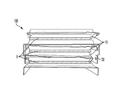
thereto, a battery cell, a battery shell, a battery module, a battery pack, a
battery box, a battery
cell casing, a pack shell, a battery lid and tray, a thermal management
system, an inverter, a
battery housing, a module housing, a module racking, a battery side plate, a
battery cell
- 19 -
Date Recue/Date Received 2023-08-15
enclosure, a cooling module, a cooling tube, a cooling fin, a cooling plate, a
bus bar, a battery
frame, an electrical connection, metal wires, copper or aluminum conductors or
cables, any part
of a stationary energy storage system, or any combination thereof.
[0092] As described above, the adhesive coating composition and powder
coating
composition may be applied over any of these substrates to form an
electrically insulating
coating (i.e., dielectric coating), a thermally conductive coating, or an
electrically insulating and
thermally conductive coating, as described herein.
[0093] As illustrated in FIGS. 1 to 9, a coating layer may be deposited
onto surface of a
substrate from one of the powder coating compositions disclosed herein. An
adhesive may be
formed from the application of one of the adhesive compositions disclosed
herein on at least a
portion of the coating layer such that the adhesive is between the coating
layer and a surface of a
second substrate.
[0094] FIGS. 1 to 9 illustrate non-limiting examples of battery assembly
components and
constructions as well as non-limiting applications or use of compositions as
disclosed herein in
said battery assemblies. Although FIGS. 1 to 9 illustrate specific examples of
cell shapes and
cell arrangements, cells may be arranged in any configuration known to those
skilled in the art.
Additionally, the cured compositions may be used to form pads, adhesives,
coatings, pottants and
the like, to provide thermal protection between battery cells, within battery
modules and/or
within battery packs. These materials may be used on any surface or in any
space within such
battery assemblies. For example, compositions disclosed herein also may be
useful in battery
assemblies including, but not limited to, cell to module (FIGS. 3, 4, 6B),
module to pack (FIGS.
6C, 7), cell to pack (FIG. 8), and cell to chassis battery assemblies (FIG.
9). Such battery
assemblies may be used in, but not limited to, any aforementioned application.
[0095] Battery assemblies may be any combination of one or more battery
cells, the
interconnects which provide electrical conductivity between them, as well as
ancillary
components such as, in non-limiting examples, control electronics and
components that ensure
the necessary structural mechanical and environmental requirements for the
operation of a
specific battery (for example, without limitation, cell interconnectors such
as wires, battery pack
enclosures including trays and lids, module enclosures, module frames and
frame plates, module
racking, cooling and heating components including cooling plates, cooling
fins, and cooling
- 20 -
Date Recue/Date Received 2023-08-15
tubes, electrical busbars, battery management systems, battery thermal
management systems,
chargers, inverters and converters).
[0096] Battery cells 10 are generally single unit energy storage
containers that may be
connected in series or in parallel. Battery cells may be any suitable size or
shape known to those
skilled in the art, such as but not limited to, cylindrical (FIGS. 1, 4 and
9), prismatic (FIGS. 2, 5-
8) and/or pouch (FIG. 3). Battery cells 10 are enclosed to provide desired
mechanical protection
and environmental isolation of the cell. For example, cylindrical and
prismatic cells may be
encased in metal cans, cases, and lids, while pouch cells may be enclosed in
multilayer laminate
foils. Battery terminals 1 connect the electrodes inside the battery cell to
the electrical circuit
outside the battery cell, with one being a positive terminal and the other
being a negative
terminal. As illustrated in FIG. 4, battery cells 10 may be connected by
interconnector wires 5
with other battery cells 10 in series or in parallel to enable an electric
current to flow between
cells 10.
[0097] As illustrated in FTGS. 3, 4, 5, 6B, 6C, and 7, battery cells 10
may be arranged in
modules 100 comprising multiple cells 10 connected in series or in parallel.
The modules 100
may include a partial enclosure of the arranged cells 10. Ancillary
components, such as those
aforementioned, may be included. Spaces of any dimensions may be located
between the
plurality of cells, ancillary components, base, and/or any interior surface of
the module wall or
other enclosure 120.
[0098] FIG.1 illustrates a top-down view of cylindrical battery cells 10
having terminals
1. As shown, the cells are arranged in rows with either cooling tubes 3 or
dielectric and thermal
insulation paper (insulation paper) 4 between them. As shown, materials, such
as powder
coatings and adhesive 6 formed from the compositions disclosed herein,
respectively, may be
positioned between the cells 10, cooling tubes 3 and/or insulation paper 4.
[0099] FIG.2 illustrates an exploded isometric view of an array of
prismatic battery cells
10. As shown, each prismatic cell 10 may comprise a top 11, a bottom, and
walls 13 positioned
between the top and bottom and each having a surface. As shown, coatings
(i.e., powder
coatings and adhesives) 8 formed from the compositions disclosed herein, may
be positioned
between surfaces of cell walls 13 of adjacent cells 10.
[0100] FIG.3 illustrates a cut-out front view of an array of pouch battery
cells 10 in a
module 100. The module walls 120 may partially encase the cells 10. As shown,
materials such
-21 -
Date Recue/Date Received 2023-08-15
as coatings (i.e., powder coatings and adhesives) 8 formed from the
compositions disclosed
herein, may be positioned between surfaces of cells 10.
[0101] FIG.4 illustrates an isometric view of cylindrical cells 10 in a
battery module 100.
Each cell may comprise a top 11, a bottom 12, and walls 13 positioned between
the top and
bottom and each having a surface. The top 11 and the bottom 12 may be
oppositely charged
terminals with one being a positive terminal 1 and the other being a negative
terminal (not
shown). The battery cells may be connected at their terminals by
interconnectors such as wires 5
and the like to enable an electric current to flow between the electric cells.
The module 100 or
module walls 120 may form a space having a volume. The cells 10 may be
positioned within the
space to consume a portion of the volume. The material, such as powder
coatings and adhesives
7 formed from the compositions disclosed herein, may be positioned within the
space to
consume a portion of the volume such that the material is adjacent to a
surface of a cell wall 13
and/or an interior surface of one of the walls 120 of the module 100.
[0102] FIG.5 illustrates an exploded perspective view of a battery module
100 comprised
of one or more arrays of battery cells 10, a cooling fin 230, and/or a cooling
plate 240.
Materials, such as coatings (i.e., powder coatings and adhesives) 8 formed
from the compositions
disclosed herein, may be positioned between cells 10. Additional coatings 8
may be positioned
between the cells 10, the cooling fin 230 and/or the cooling plate 240.
Additional coatings may
be positioned between the battery cell array and an interior surface of walls
120. Other coatings
8 may be positioned adjacent to an exterior surface of the walls 120.
[0103] FIG.6 illustrates an isometric view of a battery cell 10 (FIG. 6A)
to battery
module 100 (FIG. 6B) to battery pack 200 (FIG. 6C) battery assembly. The
battery module 100
comprises a plurality of battery cells 10 and the battery pack 200 comprises a
plurality of battery
modules 100.
[0104] FIG.7 illustrates a perspective view of a battery pack 200 cutout.
The battery
pack includes a plurality of battery modules 100 and cells 10 within each
module 100. The base
of the battery pack 200 comprises a cooling plate 240. Materials, such as
powder coatings and
adhesives, 9 formed from the compositions disclosed herein, may be positioned
between the
cooling plate 240 and interior surface of a wall of the battery pack 200.
Materials, such as
powder coatings and adhesives 8 formed from the compositions disclosed herein,
may be
positioned between cells 10 within modules 100.
- 22 -
Date Recue/Date Received 2023-08-15
[0105] FIG.8 illustrates an isometric view of a cell 10 to pack battery
200 assembly.
Cells 10 are arranged within the pack 200 (without being in separate modules).
[0106] In other cases, the battery cells may be arranged on or within an
article such as,
but not limited to, a cell to chassis battery assembly, as illustrated in FIG.
9, wherein one or more
cells is used to construct the battery assembly without prior assembly of the
cells into modules
and/or packs. FIG. 9 illustrates an isometric cut-out view of a cell to
chassis battery assembly
300. Cells 10 are arranged on a base comprising the undercarriage 55 and
supported by the
vehicle frame 45 and under the vehicle interior floor 35.
[0107] Any battery assembly may further comprise a thermal management
system (not
shown) comprising air or fluid circuits which may be liquid based (for example
glycol solutions)
or direct refrigerant based. The fire-retardant material may be adjacent to
any of these
components of the battery assembly.
[0108] It has been surprisingly discovered that the coated substrate may
have a thermal
resistance of no more than 2.0 C/VV as measured using a TIM Thermal
Resistance and
Conductivity Measurement Apparatus (model LW-9389) in accordance with ASTM
D5470
(steady-state method), such as 0.5 C/W to 2.0 C/VV.
[0109] The following examples are for illustration purposes only, which,
however, are
not to be considered as limiting.
EXAMPLES
Powder Coating Compositions
[0110] For Example 1, 0.6 grams of carbon black, 25.44 grams of barium
sulfate, and
0.15 grams of aluminum oxide were added to an epoxy-containing powder coating
composition
crosslinked with a phenolic curative. For Example 2, 0.6 grams of carbon
black, 50 grams of
aluminum trihydroxide, and 0.15 grams of aluminum oxide were added to an epoxy-
containing
powder coating composition crosslinked with a phenolic curative.
[0111] The electrically insulative fillers were incorporated into the
chips of the powder
coating compositions. The chips were then milled in a Dongyuan ACM -05 Air
Classifying
Mill to obtain a fine powder, followed by tap-sieving with a 160 mesh to
achieve final particle
size ranging between 5 to 100 microns with a majority of the particles being
from 30 to 52
microns by volume. The resulting coating composition for each of Examples 1
and 2 was solid
particulate powder coating composition that was free flowing.
- 23 -
Date Recue/Date Received 2023-08-15
Evaluation of Dielectric Performance.
[0112] The powder coating compositions of each of Examples 1 and 2 was
electrostatically applied with an Encore Nordson powder coating cup gun with a
3mm flat spray
nozzle onto aluminum substrates (AQT-412 panels of alloy 3003, bare mill
finish from Q-LAB)
at the following parameters: voltage at of 60kV, amperage restriction at
201iA, 10 psi atomizing
and 10 psi conveying flow air.
[0113] For testing Dielectric Breakdown Voltage, a coating with a dry film
thickness of
150-200 gm was formed on the aluminum panel from the powder coating
composition of
Example 1 or Example 2. The panels were baked at 190 C for 20 minutes, and
then cooled down
at room temperature to get the final sample. The Dielectric Breakdown Voltage
of each sample
was measured using a Sefelec Dielectric Strength Tester RMG12AC-DC in
accordance with
ASTM D149-09 Dielectric Breakdown Voltage and Dielectric Strength test. The
measurement
adopted the following parameters: Voltage limit 12.0 kV DC, Imax Limit: 0.1
mA, 10 second
ramp, 20 second dwell, and 2 second fall.
[0114] Specifically, the measurement included the following steps: (1) the
sample (the
coated aluminum panel) was placed in the electrically insulated box of the
Dielectric Strength
Tester and on the brass flat top cylinder electrical contact, with the coating
side of the sample
facing the contact; (2) the brass convex tip was lowered and rested on the
sample's backside (the
opposite side of the coating side), and then the box was sealed; (3) the
Dielectric Strength Tester
was run three times and the values were averaged (reported in Table 2).
Evaluation of Thermal Conductivity.
[0115] The powder coating compositions of each of Examples 1 and 2 was
electrostatically applied with an Encore Nordson powder coating cup gun with a
3mm flat spray
nozzle onto aluminum substrates (AQT-412 panels of alloy 3003, bare mill
finish from Q-LAB)
at the following parameters: voltage at of 60kV, amperage restriction at 20 A,
10 psi atomizing
and 10 psi conveying flow air.
[0116] For testing Thermal Conductivity, a powder coating with a dry film
thickness of
100 pm, 160 i_tm or 220 i_tm was formed on the aluminum panels from the powder
coating
compositions of Examples 1 or 2. Powder coatings having a thickness of either
160 pm or 220
gm were formed using a two-step application process to arrive at the final
desired coating
thickness. All panels were baked at 190 C for 20 minutes, and then cooled down
at room
- 24 -
Date Recue/Date Received 2023-08-15
temperature. Formed coatings were removed from the panels to obtain "free"
films, which were
cut into square samples of 26mm*26mm for measurement.
[0117] The Thermal Conductivity of each sample was measured by TIM Thermal
Resistance and Conductivity Measurement Apparatus (model is LW-9389) and in
accordance
with ASTM D5470 (steady-state methods). The test results of Dielectric
Breakdown Voltage
and Thermal Conductivity of the Examples 1 and 2 are summarized in Table 2.
TABLE 2: Dielectric Breakdown Voltage and Thermal Conductivity of Coatings
Formed
From Powder Compositions
Example 1 Example 2
Thermal Conductivity W/K-m 0.292 0.719
Dielectric Breakdown (kV) 12 12
Thermal Conductive Adhesives (TCA)
[0118] For Example 3, 194.65 grams of aluminum oxide were added to part A
(isocyanate-containing component) of a two-component polyurethane-based
adhesive
composition. Part B comprised a polyol and an accelerator. For Example 4, 40
grams of
aluminum oxide and 40 grams of aluminum hydroxide were added to part A
(isocyanate-
containing component) of a two-component polyurethane-based adhesive
composition. Part B
comprised a polyol and an accelerator.
[0119] The method for preparing the TCA compositions comprised:
[0120] (i) Dehydration of thermally conductive fillers: The thermally
conductive fillers
S403Z and APYRAL 20X were dehydrated before use: weighed and deposed S403Z and
APYRAL 20X in an oven at 105 C,until the moisture content in each filler <
1000ppm.
[0121] (ii) Mixing process of Part A: The adhesive components and the
thermally
conductive fillers were weighed in a planetary stirring kettle and mixed in
the kettle for 25
minutes with the speed of the stirring paddle of 35 RPM and the speed of the
dispersing plate of
359RPM. From 5 minutes of stirring, the kettle was vacuumized to a vacuum
degree of -0.99-1
through a vacuum pump. After stirring, the vacuum pump was turned off and
nitrogen gas was
introduced into the kettle to make up the air pressure balance. Then, the
mixture A was removed
from the kettle and packed into cartridges by a press machine.
[0122] (iii) Mixing process of Part B: The adhesive components were
weighed in a
planetary stirring kettle and mixed in the kettle for 25 minutes with the
speed of the stirring
- 25 -
Date Recue/Date Received 2023-08-15
paddle of 35 RPM and the speed of the dispersing plate of 359RPM. From 5
minutes of stirring,
the kettle was vacuumized to a vacuum degree of -0.99-1 through a vacuum pump.
After
stirring, the vacuum pump was turned off and nitrogen gas was introduced into
the kettle to make
up the air pressure balance. Then, the mixture B was removed from the kettle
and packed into
cartridges by a press machine.
- 26 -
Date Recue/Date Received 2023-08-15
Evaluation of Thermal Conductivity.
[0123] The cartridges of Part A and Part B were applied with a SULZER
DP2X400 glue
gun at 3-6bar air pressure onto PET film, and covered with another PET film.
Samples were put
into a tablet machine for pressure and control the thickness with 0.2-3.0mm
thickness frame as
spacer. After the films were fully cured, they were removed and the thermal
conductivity was
tested with a thermal conductivity tester in accordance with ASTM D5470.
Two-layer system
[0124] The powder coatings of Examples 1 and 2 were applied to substrates
(A13003
Panel) according to the same procedure described above, and the thermal
conductive adhesive
coatings of Examples 3 and 4 were applied above the powder coatings according
to the same
procedure as described above. During the application of the thermal conductive
adhesive
coatings, stainless steel balls of diameter of 0.5 mm were used as spacer to
control the thickness
of the thermal conductive adhesive coatings. Another A13003 panel was covered
on the thermal
conductive adhesive coatings, and clamps were used to combine the two A13003
panels tightly
till the coatings were fully cured.
[0125] The lap shear strength of the thermally conductive adhesive was
measured
according to ASTM D1002-10 using 2024-T3 aluminum substrate of 1.6 mm
thickness, as
measured by an INSTRON 5567 machine in tensile mode with a pull rate of 1.3 mm
per minute.
Bond strength was measured according to GB/T5210 using an aluminum column of
100*10*10
mm by a universal tensile testing machine with a pull rate of 5 mm per minute.
[0126] The Thermal Resistance of the two layer systems were measured by
TIM Thermal
Resistance and Conductivity Measurement Apparatus (model is LW-9389) and in
accordance
with ASTM D5470 (steady-state methods).
Table 3. Coated Substrates
Examples Thermal Lap Shear Bond Thermal Thermal
(Powder + Conductivity Strength of Strength of Conductivity of
Resistance
Adhesive) of Powder Adhesive Adhesive Adhesive of Adhesive
(W/mK) (MPa) (MPa) (W/mK) + Powder
Coating
( C/w)
-27 -
Date Recue/Date Received 2023-08-15
1 + 3 0.292 13.75 10.1 1.4 1.520
1 + 4 0.292 9.89 9.27 2.0 1.382
2 + 3 0.719 15.07 12.54 1.4 1.064
2 + 4 0.719 13.01 12.54 2.0 0.928
[0127] These data demonstrate that the combination of thermally conductive
dielectric
powder coating with a lower thermally conductive adhesive results in a coating
stack having
good adhesive performance (lap shear and bond strength) and a low thermal
resistance (i.e.,
Examples 2+3) compared to more highly filled systems (Examples 2+4), which had
lower lap
shear performance.
[0128] Whereas particular examples of this disclosure have been described
above for
purposes of illustration, it will be evident to those skilled in the art that
numerous variations of
the details of the present disclosure may be made without departing from what
is defined in the
appended claims.
- 28 -
Date Recue/Date Received 2023-08-15