Note: Descriptions are shown in the official language in which they were submitted.
LED LIGHT SOURCE
FIELD
[0001] This application relates to the field of LED light sources and
apparatus
including the same.
INTRODUCTION
[0002] A light-emitting diode (LED) is a semiconductor light source
that emits
light when activated. Generally, LEDs have lower energy consumption and longer
lifespans as compared with traditional light sources, such as incandescent and
halogen lights.
SUMMARY
[0003] In one aspect, a LED light source is provided. The LED light
source,
may include a longitudinally extending first light guide, a housing, and a
cartridge.
The first light guide having a longitudinally extending light emitting face,
the light
emitting face having a first end face and a longitudinally spaced apart second
end
face. The housing having a first recess, the recess having a first side
proximate the
first end face of the first light guide and a longitudinally spaced apart
opposed face,
the first recess extending generally transverse to the first light guide from
an
insertion end to a transversely spaced apart inner end. The cartridge
slideably
receivable in the first recess and having a plurality of LEDs on a first face
of the
cartridge, the first face extending generally transverse to the first light
guide when
the cartridge has been inserted into the first recess, the first face having
an inner
end and an outer end. The cartridge may be movable from an insertion position
in
which the inner end of the first face of the cartridge is spaced from the
first side of
the first recess when the inner end of the first face of the cartridge is
positioned at
the insertion end, to an inserted position in which the first face of the
cartridge is
adjacent the first side of the first recess when the cartridge is inserted
into the first
recess.
[0004] In some embodiment, the LED light source further includes a
biasing
member biasing the cartridge to the inserted position.
[0005] In some embodiments, the first recess includes a cam member
whereby, as the cartridge is inserted into the first recess, the cartridge is
guided
towards the inserted position.
- 1 -
Date Recue/Date Received 2023-08-23
[0006] In some embodiments, the LED light source may further include
a
biasing member biasing the cartridge to the inserted position.
[0007] In some embodiments, the cartridge is rigid and the biasing
member
is provided at the inner end of the first recess whereby a biasing force
provided by
the biasing member when the cartridge is in the inserted position biases the
outer
end of the cartridge to a position proximate the light guide.
[0008] In some embodiments, the LED light source may further include
a
driving member moveably mounted in the housing and driving the cartridge from
a
position in which the first face of the cartridge is spaced from the first
side of the
first recess to the inserted position.
[0009] In some embodiments, the LEDs are provided only on the first
face of
the cartridge.
[0010] In some embodiments, the LED light source may further include
a
second light guide having an first end face and a longitudinally extending
light
emitting face, wherein the first recess has a third side proximate the first
end face
of the second light guide and the LEDs are also provided on a second face of
the
cartridge, wherein when the cartridge is in the inserted position, the second
face of
the cartridge is adjacent the third side of the first recess.
[0011] In some embodiments, the light guides extend in different
directions.
[0012] In some embodiments, the light guides extend in different directions
that re about 90 apart.
[0013] In some embodiments, the cartridge further includes a heat
sink.
[0014] In some embodiments, the cartridge further includes the heat
sink.
[0015] In some embodiments, the cartridge further includes a
substrate, the
LEDs are provided on the substrate and the substrate is removable from the
heat
sink.
[0016] In some embodiments, the heat sink is provided in the housing
and
the cartridge has a side in thermal contact with the heat sink when the
cartridge is
in the inserted position.
[0017] In some embodiments, the LED light source may further include a
second light guide extending in the same direction as the first light guide,
the second
- 2 -
Date Recue/Date Received 2023-08-23
light guide having a first end face and a longitudinally extending light
emitting face
oriented in the same direction as the light emitting face of the first light
guide, and
the housing further includes a second recess which slideably receives another
cartridge having LEDs on a face thereof.
[0018] In some embodiments, the second recess is positioned proximate the
first recess and, when inserted the LEDs of the first cartridge face an
opposed
direction to the LEDs of the second cartridge.
[0019] In some embodiments, the second recess is positioned spaced
from
the first recess and, when inserted the LEDs of the first cartridge face a
first direction
and the LEDs of the second cartridge face the first direction.
[0020] In some embodiments, the LED light source may further include
a
second recess positioned at the second end face of the first light emitting
member
and, when inserted, the LEDs of the first cartridge face an opposed direction
to the
LEDs of the second cartridge.
[0021] In another aspect, a LED light source is provided. The LED light
source includes a longitudinally extending first light guide, a housing, and a
cartridge. The first light guide has a longitudinally extending light emitting
face, the
light emitting face having a first end face and a longitudinally spaced apart
second
end face. The housing has a first side proximate the first end face of the
first light
.. guide. The cartridge is mountable to the first side of the housing and has
at least
one LED on a first face of the cartridge, the first face extending generally
transverse
to the first light guide when the cartridge has been mounted to the housing.
When
the cartridge is mounted to the first side of the housing, the first face of
the cartridge
is adjacent the first end face.
[0022] In some embodiments, the cartridge has mechanical engagement
members which are releasably securable to mating mechanical engagement
members of the housing.
[0023] In some embodiments, the LED light source may further include
at
least one screw member that releasably secures the cartridge to the first side
of the
housing.
[0024] In some embodiments, the screw members are non-removably
secured to the housing.
- 3 -
Date Recue/Date Received 2023-08-23
[0025] In another aspect, a LED light bulb is provided. The LED light
bulb
may include an engagement end electrically connectable to a socket; a housing
having a light transmitting surface and an interior; and, a cartridge
removably
receivable in the interior and having a plurality of LEDs.
[0026] In some embodiments, the LED light bulb has a first recess, the
recess having an insertion end proximate an outer surface of the LED light
bulb and
a longitudinally spaced apart inner end and the cartridge is slideably
receivable in
the first recess.
[0027] In some embodiments, the plurality of LEDs are provided on a
first
face of the cartridge.
[0028] In some embodiments, the LEDs are provided on a plurality of
faces
of the cartridge.
[0029] In some embodiments, the cartridge is generally cylindrical in
shape.
[0030] In some embodiments, the recess is provided in the engagement
end.
[0031] In some embodiments, the recess is provided in the housing.
[0032] In some embodiments, the housing includes a light guide and
the
LEDs are positioned against an end of the light guide when installed in the
LED light
bulb.
[0033] In some embodiments, all of an exterior of the housing is made
of a
material having a light transmitting surface.
[0034] In some embodiments, the LED light bulb is in the shape of an
incandescent or halogen light bulb.
[0035] In another aspect, a LED light source is provided. The LED
light
source may include a longitudinally extending light guide having a
longitudinally
extending light emitting face having a length, a first end face and a
longitudinally
spaced apart second end face and a LED light source is provided at least at
the
first end face. The light emitting face has a plurality of light emitting
locations
provided thereon. The density of the light emitting locations increases from
the first
end face towards the second end face.
[0036] In some embodiments, a first LED light source is provided at the
first
end face and a second LED light source is provided at the second end face
wherein
- 4 -
Date Recue/Date Received 2023-08-23
the density of the light emitting locations increases from each of the first
end face
and the second end face to a middle of the light emitting face.
[0037] In some embodiments, the light emitting locations are
positioned to
provide a generally even level of illumination along the length of the light
emitting
surface.
[0038] In some embodiments, a level of illumination provided at the
middle
of the light emitting surface is 20% of a level of illumination provided at
the first
end face.
[0039] In some embodiments, a level of illumination provided at the
middle
of the light emitting surface is 10% of a level of illumination provided at
the first
end face.
[0040] In some embodiments, an image is provided in front of at least
a
portion of the light emitting face and the light emitting locations are
positioned such
that a person viewing the image views a generally evenly illuminated image.
[0041] In some embodiments, the image has at least area that has at least
one of a different colour or a different density of the image and the light
emitting
locations are positioned such that a person viewing the image views a
generally
evenly illuminated image.
[0042] In some embodiments, the LED light source is provided only at
the
first end face wherein the density of the light emitting locations increases
from the
first end face to the second end face.
[0043] In some embodiments, the light emitting locations are
positioned to
provide a generally even level of illumination along the length of the light
emitting
surface.
[0044] In some embodiments, a level of illumination provided at the second
end face of the light emitting surface is 20% of a level of illumination
provided at
the first end face.
[0045] In some embodiments, a level of illumination provided at the
second
end face of the light emitting surface is 10% of a level of illumination
provided at
the first end face.
[0046] In some embodiments, the light emitting locations comprise
discontinuities provided in the light emitting face.
- 5 -
Date Recue/Date Received 2023-08-23
[0047] In some embodiments, the light emitting locations comprise a
light
scattering material applied to the light emitting surface.
[0048] In some embodiments, the light emitting locations comprise a
fluorescent material.
[0049] In another aspect, a frame for a work of art is provided. The frame
may include at least one side panel extending around a perimeter and defining
an
inner opening in which the work of art is displayable. The at least one side
panel
may include a longitudinally extending light guide having a longitudinally
extending
light emitting face that faces inwards towards another portion of the at least
one
side panel. The longitudinally extending light emitting face has a length, a
first end
face and a longitudinally spaced apart second end face and a LED light source
is
provided at least at the first end face. The light emitting face has a
plurality of light
emitting locations provided thereon. The density of the light emitting
locations
increases from the first end face towards the second end face.
[0050] In some embodiments, the fame is in the shape of a parallelogram
and includes four side panels, each of which includes a longitudinally
extending
light guide having a light emitting face that faces onwards.
[0051] In some embodiments, each light emitting face has an inner
side
positioned proximate a plane in which the work of art seats when mounted in
the
frame and a spaced apart outer side and the inner side is position forward of
the
plane.
[0052] In some embodiments, the light emitting face has an inner side
positioned proximate a plane in which the work of art seats when mounted in
the
frame and a spaced apart outer side and the inner side is position forward of
the
plane.
[0053] In some embodiments, a first LED light source is provided at
the first
end face and a second LED light source is provided at the second end face
wherein
the density of the light emitting locations increases from each of the first
end face
and the second end face to a middle of the light emitting face.
[0054] In some embodiments, the LED light source is provided only at the
first end face wherein the density of the light emitting locations increases
from the
first end face to the second end face.
- 6 -
Date Recue/Date Received 2023-08-23
[0055] In another aspect, a backlight frame for a work of art is
provided. The
backlight frame may include a frame member extending around a perimeter and
defining an inner opening in which the work of art is displayable, and a
longitudinally
extending light guide positioned rearward of the opening and facing towards
the
opening. The longitudinally extending light guide has a longitudinally
extending light
emitting face having a length, a first end face and a longitudinally spaced
apart
second end face and a LED light source is provided at least at the first end
face.
The light emitting face has a plurality of light emitting locations provided
thereon.
The density of the light emitting locations increases from the first end face
towards
the second end face.
[0056] In some embodiments, a first LED light source is provided at
the first
end face and a second LED light source is provided at the second end face
wherein
the density of the light emitting locations increases from each of the first
end face
and the second end face to a middle of the light emitting face.
[0057] In some embodiments, the LED light source is provided only at the
first end face wherein the density of the light emitting locations increases
from the
first end face to the second end face.
[0058] In some embodiments, the work of art that transmits light is
provided
in front of at least a portion of the light emitting face and the light
emitting locations
are positioned such that a person viewing the work of art views a generally
evenly
illuminated work of art.
[0059] In some embodiments, the work of art has at least area that
has at
least one of a different colour or a different density of the image and the
light
emitting locations are positioned such that a person viewing the work of art
views a
generally evenly illuminated work of art.
[0060] In some embodiments, the light emitting locations comprise a
fluorescent material.
[0061] In another aspect, a frame for a work of art is provided. The
frame
may include at least one side panel defining an inner opening in which the
work of
art is displayable, the inner opening extending in a plane, the at least one
side panel
including a longitudinally extending light guide having a longitudinally
extending
light emitting face that faces inwards towards the inner opening in a
direction
generally parallel to the plane. The light emitting face has an inner side
positioned
- 7 -
Date Recue/Date Received 2023-08-23
proximate the plane and a spaced apart outer side and at least one LED
providing
a light source for the light guide.
[0062] In some embodiments, the inner side of the light emitting face
is
spaced from the plane.
[0063] In some embodiments, the inner side of the light emitting face is
spaced from 0.25 to 1 inch from the plane.
[0064] In some embodiments, the light guide has a first end face and
a
longitudinally spaced apart second end face and the light source is provided
at least
at the first end face.
[0065] In some embodiments, a first light source is provided at the first
end
face and a second light source is provided at the second end face.
[0066] In some embodiments, the fame is in the shape of a
parallelogram
and includes four side panels, each of which includes a longitudinally
extending
light guide having a longitudinally extending light emitting face that faces
inwards
towards the inner opening in a direction generally parallel to the plane, each
light
emitting face has an inner side positioned proximate the plane and a spaced
apart
outer side.
[0067] In some embodiments, the light emitting faces are positioned
forward
of the plane.
[0068] In some embodiments, the fame includes a plurality of side panels
which meet at corners, at least some of the side panels comprise a
longitudinally
extending light guide having a longitudinally extending light emitting face
that faces
inwards towards the inner opening in a direction generally parallel to the
plane, each
light emitting face has a first end face and a longitudinally spaced apart
second end
face and the light source is provided at least at the first end face, wherein
the light
sources are provided in corners of the parallelogram.
[0069] In some embodiments, the fame is in the shape of a
parallelogram,
each of the side panels includes a longitudinally extending light guide and
the light
sources are provided in the corners of the parallelogram.
[0070] In some embodiments, the frame may further include a sensor that
detects a condition in a space in front of a location in which the frame is
located and
a controller that adjusts at least one of a level of intensity of light
emitted by the light
- 8 -
Date Recue/Date Received 2023-08-23
source and the colour of light emitted by the light source based upon a signal
provided by the sensor.
[0071] In some embodiments, the condition includes at least one of a
level
of illumination, a colour of illumination, motion of a body, a noise level, a
signal
issued by a person.
[0072] In some embodiments, the light source includes LEDs of at
least two
different colours.
[0073] In some embodiments, the frame may further include a manually
actuatable switch operatively connected to the light source wherein operation
of the
switch adjusts at least one of a level of intensity of light emitted by the
light source
and the colour of light emitted by the light source based upon a signal
provided by
the switch.
[0074] In some embodiments, the frame may further include an energy
storage member.
[0075] In some embodiments, the energy storage member includes a
rechargeable battery.
[0076] In some embodiments, the at least one LED is operable to
selectively
emit one or more colours of light.
[0077] In some embodiments, the at least one LED is operable to
selectively
illuminate part of a work of art placed in the fame.
[0078] In another aspect, a backlight frame for a work of art is
provided. The
backlight frame may include a frame member that defines an inner opening in
which
the work of art is displayable, the inner opening extending in a plane, and a
longitudinally extending light guide positioned rearward of the opening and
facing
towards the opening. The longitudinally extending light guide has a
longitudinally
extending light emitting face spaced rearward of the plane and having a
length, a
first end face and a longitudinally spaced apart second end face and a LED
light
source is provided at least at the first end face.
[0079] In some embodiments, the light emitting face is spaced
rearward from
the plane.
[0080] In some embodiments, the light emitting face is spaced from
0.25 to
1 inch from the plane.
- 9 -
Date Recue/Date Received 2023-08-23
[0081] In some embodiments, the light guide has a first end face and
a
longitudinally spaced apart second end face and the LED light source is
provided
at least at the first end face.
[0082] In some embodiments, a first light source is provided at the
first end
face and a second light source is provided at the second end face.
[0083] In some embodiments, the frame may further include a sensor
that
detects a condition in a space in front of a location in which the frame is
located and
a controller that adjusts at least one of a level of intensity of light
emitted by the light
source and the colour of light emitted by the light source based upon a signal
provided by the sensor.
[0084] In some embodiments, the condition includes at least one of a
level
of illumination, a colour of illumination, motion of a body, a noise level, a
signal
issued by a person.
[0085] In some embodiments, the light source includes LEDs of at
least two
different colours and
[0086] In some embodiments, the frame may further include a manually
actuatable switch operatively connected to the light source wherein operation
of the
switch adjusts at least one of a level of intensity of light emitted by the
light source
and the colour of light emitted by the light source based upon a signal
provided by
the switch.
[0087] In some embodiments, the frame may further include an energy
storage member.
[0088] In some embodiments, the energy storage member includes a
rechargeable battery.
[0089] In some embodiments, the at least one LED is operable to selectively
emit one or more colours of light.
[0090] In some embodiments, the at least one LED is operable to
selectively
illuminate part of a work of art placed in the fame.
[0091] In another aspect, a LED light source is provided. The LED
light
source may include a longitudinally extending light guide, at least one LED,
and a
diffuser. The longitudinally extending light guide may have a first
longitudinally
extending light emitting face, the first light emitting face having a first
end face, a
- 10 -
Date Recue/Date Received 2023-08-23
longitudinally spaced apart second end face, and first and second side faces
extending between the first and second end faces. The at least one LED is
provided
at the first end face. The diffuser includes a central panel that is spaced
from and
facing the first light emitting face.
[0092] In some embodiments, the central panel of the diffuser is positioned
from 0.25 to 3 inches from the light emitting surface.
[0093] In some embodiments, the diffuser is composed of at least one
of
acrylic, polypropylene and polycarbonate, wherein the diffuser is at least
translucent.
[0094] In some embodiments, the diffuser extends over the first and second
side faces and the light emitting face.
[0095] In some embodiments, the diffuser is white.
[0096] In some embodiments, the central panel has a first end, a
longitudinally spaced apart second end, and first and second sides each of
which
extends longitudinally between the first and second ends, and the diffuser
further
includes a first side panel extending between the first and second ends the
central
panel and provided on the first side of the central panel and a second side
panel
extending between the first and second ends the central panel and provided on
the
second side of the central panel.
[0097] In some embodiments, the light guide has a second light emitting
face
spaced from and opposed to the first light emitting face and facing in a
direction
opposed to a direction that the first light emitting member faces.
[0098] In some embodiments, the light guide has a longitudinally
extending
rear face spaced from and opposed to the first light emitting face, and the
LED light
source further includes a reflector facing the rear face.
[0099] In some embodiments, the reflector is spaced from the rear
face.
[00100] In some embodiments, the reflector abuts the rear face.
[00101] In some embodiments, the reflector has a surface facing the
rear face,
wherein the surface is provided with a white coating.
[00102] In some embodiments, the white coating includes titanium dioxide.
-11 -
Date Recue/Date Received 2023-08-23
[00103] In some embodiments, the LED light source may further include
an
image provided in front of the light emitting face, the image having at least
one
portion that has one or more of a different colour or light transmissivity,
wherein a
surface of the reflector facing the light guide has more than one colour and
the
colours are positioned to enhance the image when viewed by a user.
[00104] In some embodiments, a portion of the reflector has a colour
selected
to increase the visibility of the portion of the image.
[00105] In some embodiments, the reflector has a surface facing the
rear face,
wherein the surface is provided with a UV paint or fluorescent paint.
[00106] In some embodiments, the at least one LED is operable to
selectively
emit one or more colours of light.
[00107] In another aspect, a LED light source is provided. The LED
light
source includes a longitudinally extending light guide, at least one LED, and
a
reflector. The longitudinally extending light guide having a first
longitudinally
extending light emitting face, a longitudinally extending rear face spaced
from and
opposed to the first light emitting face, the first light emitting face having
a first end
face, a longitudinally spaced apart second end face, and first and second side
faces
extending between the first and second end faces. The at least one LED is
provided
at the first end face. The reflector faces the rear face.
[00108] In some embodiments, the reflector is spaced from the rear face.
[00109] In some embodiments, the reflector abuts the rear face.
[00110] In some embodiments, the reflector has a surface facing the
rear face,
wherein the surface is provided with a white coating.
[00111] In some embodiments, the white coating includes titanium
dioxide.
[00112] In some embodiments, the white reflector has a surface facing the
rear face, wherein the surface is provided with a UV paint.
[00113] In some embodiments, the LED light source may further include
an
image provided in front of the light emitting face, the image having at least
one
portion that has one or more of a different colour or light transmissivity,
wherein a
surface of the reflector facing the light guide has more than one colour and
the
colours are positioned to enhance the image when viewed by a user.
- 12 -
Date Recue/Date Received 2023-08-23
[00114] In some embodiments, a portion of the reflector has a colour
selected
to increase the visibility of the portion of the image.
[00115] In some embodiments, the at least one LED is operable to
selectively
emit one or more colours of light.
[00116] In another aspect, a LED light source is provided including a
longitudinally extending light guide, and a power supply. The longitudinally
extending light guide has a first end face and a longitudinally spaced apart
second
end face and at least one LED provided at the first end face. The power supply
includes a plurality of batteries operatively connected to the at least one
LED in a
first mode in which the power supply provides a first power to the at least
one LED
and a second mode in which the power supply provides a second power different
to the first power to the at least one LED.
[00117] In some embodimentsõ in the first mode, two or more of the
batteries
are connected in series.
[00118] In some embodimentsõ in the second mode, two or more of the
batteries are connected in parallel.
[00119] In some embodiments, the plurality of batteries comprise a
first
battery and a second battery and, in the first mode, the first and second
batteries
are connected in series.
[00120] In some embodimentsõ in the second mode, the first and second the
batteries are connected in parallel.
[00121] In some embodiments, the LED light source may further include
a
circuit which includes a sensor and the power supply whereby, when the sensor
senses a condition, the sensor issues a signal which causes the power supply
to
change from the first mode to the second mode.
[00122] In some embodiments, the sensor includes a motion sensor.
[00123] In some embodiments, the sensor includes a noise sensor.
[00124] In some embodiments, the sensor includes a light intensity
sensor.
[00125] In some embodiments, the LED light source may further include
a
manually operable switch operatively connected to the power supply, the switch
- 13 -
Date Recue/Date Received 2023-08-23
having a first position in which the power supply is in the first mode and a
second
position in which the power supply is in the second mode.
[00126] In another aspect, a LED light source is provided. The LED
light
source includes a circuit including a plurality of LEDs. The LEDs are
connected in
parallel and each of the plurality of LEDs is individually electrically
connected to the
circuit by a meltable electrically conductive member.
[00127] In some embodiments, the meltable electrically conductive
member
includes fuse wire.
[00128] In some embodiments, the meltable electrically conductive
member
melts at a temperature corresponding to a temperature produced by a current
drawn by a failed LED through the meltable electrically conductive member.
[00129] In some embodiments, the meltable electrically conductive
member
melts at a temperature above about 80 C.
[00130] In some embodiments, the meltable electrically conductive
member
includes fuse wire.
BRIEF DESCRIPTION OF THE DRAWINGS
[00131] FIG. 1 is a perspective view of an LED light source in
accordance with
an embodiment;
[00132] FIG. 2 is an exploded view of the LED light source of FIG. 1;
[00133] FIG. 3 is an exploded view of a housing end member of the LED light
source of FIG. 1;
[00134] FIG. 4 is a cross-sectional view taken along line 4-4 in FIG.
1;
[00135] FIG. 5 is a cross-sectional view taken along line 5-5 in FIG.
1 and
showing a cartridge in an inserted position;
[00136] FIG. 6 is a cross-sectional view taken along line 5-5 in FIG. 1 and
showing the cartridge in an insertion position;
[00137] FIG. 7 is a cross-sectional view taken along line 5-5 in FIG.
1 and
showing the cartridge being removed;
[00138] FIG. 8 is an exploded view of a housing end member in
accordance
with another embodiment;
- 14 -
Date Recue/Date Received 2023-08-23
[00139] FIG. 9 is a cross-sectional view of the housing end member of
FIG. 8,
showing the cartridge in an inserted position;
[00140] FIG. 10 is a cross-sectional view of the housing end member of
FIG.
8, showing the cartridge in an insertion position;
[00141] FIG. 11 is a cross-sectional view of the housing end member of FIG.
8, showing the cartridge being removed;
[00142] FIG. 12 is a cross-sectional view of an LED light source
having the
housing end member of FIG. 8, and showing the cartridge in an inserted
position.
[00143] FIG. 13A is a perspective view of a housing end member in
accordance with another embodiment;
[00144] FIG. 13B is an exploded view of the housing end member of FIG.
13A;
[00145] FIG. 14 is a cross-sectional view taken along line 14-14 in
FIG. 13A,
showing a cartridge in an inserted position and a driving member in a first
position;
[00146] FIG. 15 is a cross-sectional view taken along line 14-14 in
FIG. 13A,
showing the cartridge in an insertion position and the driving member in a
second
position;
[00147] FIG. 16 is a perspective view of the housing end member of
FIG. 13A
showing the driving member in the second position and the cartridge removed;
[00148] FIG. 17 is an exploded view of a housing end member in
accordance
.. with another embodiment;
[00149] FIG. 18 is a cross-sectional view of the housing end member of
FIG.
17, showing a cartridge in an inserted position and a driving member in a
first
position;
[00150] FIG. 19 is a cross-sectional view of the housing end member of
FIG.
17, showing the cartridge in an insertion position and the driving member in a
second position;
[00151] FIG. 20 is a cross-sectional view of an LED light source in
accordance
with another embodiment;
[00152] FIG. 21 is an exploded view of a housing end member of the LED
light
source of FIG. 20;
- 15 -
Date Recue/Date Received 2023-08-23
[00153] FIG. 22 is a cross-sectional view of the housing end member,
taken
along line 22-22 in FIG. 20, showing a cartridge in an inserted position and a
driving
member in a first position;
[00154] FIG. 23 is a cross-sectional view of the housing end member,
taken
along line 23-23 in FIG. 20, showing the cartridge in the inserted position
and the
driving member in the first position;
[00155] FIG. 24 is a cross-sectional view of the housing end member,
taken
along line 23-23 in FIG. 20, showing the cartridge in the inserted position
and the
driving member in an intermediate position;
[00156] FIG. 25 is a cross-sectional view of the housing end member, taken
along line 23-23 in FIG. 20, showing the cartridge in the inserted position
and the
driving member in a second position;
[00157] FIG. 26 is a perspective view of the housing end member of the
LED
light source of FIG. 20, showing the driving member in the second position and
the
cartridge removed;
[00158] FIG. 27 is a cross-sectional view of an LED light source in
accordance
with another embodiment;
[00159] FIG. 28 is an exploded view of a housing end member of the LED
light
source of FIG. 27;
[00160] FIGS. 29-30 are cross-sectional views of the housing end member,
taken along line 29-29 in FIG. 27, showing a cartridge in the inserted
position and
a driving member in a first position;
[00161] FIG. 31 is a cross-sectional view of the housing end member,
taken
along line 29-29 in FIG. 27, showing the cartridge in the inserted position
and the
driving member in a second position;
[00162] FIG. 32 is a perspective view of the housing end member of the
LED
light source of FIG. 27, showing the driving member in the second position and
the
cartridge removed;
[00163] FIG. 33 is a cross-sectional view of an LED light source in
accordance
with another embodiment;
- 16 -
Date Recue/Date Received 2023-08-23
[00164] FIG. 34 is an exploded view of a housing end member of the LED
light
source of FIG. 33;
[00165] FIG. 35 is a perspective view of the housing end member of
FIG. 34
in an open condition;
[00166] FIG. 36 is a perspective view of a housing end member in a closed
condition in accordance with another embodiment;
[00167] FIG. 37 is a perspective view of the housing end member of
FIG. 36
in an open condition;
[00168] FIG. 38 is a cross-sectional view of an LED light source
including the
housing end member of FIG. 36;
[00169] FIG. 39 is a perspective view of a housing end member in a
closed
condition, in accordance with another embodiment;
[00170] FIGS. 40-41 are perspective views of the housing end member of
FIG.
39 in an open condition;
[00171] FIG. 42 is a cross-sectional view of an LED light source in
accordance
with another embodiment;
[00172] FIG. 43 is an exploded view of a housing end member of the LED
light
source of FIG. 42;
[00173] FIG. 44 is a cross-sectional view of the housing end member of
FIG.
43 showing a cartridge in an inserted position;
[00174] FIG. 45 is a cross-sectional view of the housing end member of
FIG.
43 showing the cartridge in an insertion position;
[00175] FIG. 46 is a cross-sectional view of the housing end member of
FIG.
43 showing the cartridge being removed;
[00176] FIG. 47 is a schematic view of a LED light source including one
cartridge in one housing end member, in accordance with an embodiment;
[00177] FIG. 48 is a schematic view of a LED light source including
one
cartridge in each of two housing end members, in accordance with an
embodiment;
[00178] FIG. 49 is a schematic view of a LED light source including
two
cartridges in one housing end member, in accordance with an embodiment;
- 17 -
Date Recue/Date Received 2023-08-23
[00179] FIG. 50 is a schematic view of a LED light source including
four
cartridges in three housing end members, in accordance with an embodiment;
[00180] FIG. 51 is a schematic view of a LED light source including
four
cartridges in four housing end members, in accordance with an embodiment;
[00181] FIG. 52 is a schematic view of a LED light source including four
cartridges in two housing end members, in accordance with an embodiment;
[00182] FIG. 53 is a schematic view of a LED light source including
eight
cartridges in two housing end members, in accordance with an embodiment;
[00183] FIG. 54 is a schematic view of a LED light source including
four
cartridges in two housing end members, each housing end member including a
heat
sink, in accordance with an embodiment;
[00184] FIG. 55 is a perspective view of a LED light source formed as
a
lightbulb in accordance with an embodiment;
[00185] FIG. 56 is an exploded view of the LED light source of FIG.
55;
[00186] FIG. 57 is a cross-sectional view taken along line 57-57 in FIG. 55
showing an open condition and a cartridge removed;
[00187] FIG. 58 is a cross-sectional view taken along line 57-57 in
FIG. 55
showing a closed condition;
[00188] FIG. 59 is a cross-sectional view taken along line 57-57 in
FIG. 55
showing the open condition;
[00189] FIG. 60 is a perspective view of a LED light source formed as
a light
bulb in accordance with another embodiment;
[00190] FIG. 61 is a perspective view of the LED light source of FIG.
60 with
a cartridge removed;
[00191] FIG. 62 is a cross-sectional view taken along line 62-62 in FIG.
60;
[00192] FIG. 63 is a perspective view of a LED light source formed as
a light
bulb in accordance with another embodiment;
[00193] FIG. 64 is a perspective view of the LED light source of FIG.
63 with
a cartridge removed;
[00194] FIG. 65 is a cross-sectional view taken along line 65-65 in FIG.
63;
- 18 -
Date Recue/Date Received 2023-08-23
[00195] FIG. 66 is a perspective view of a LED light source formed as
a light
bulb in accordance with another embodiment;
[00196] FIG. 67 is a perspective view of the LED light source of FIG.
66 with
a cartridge removed;
[00197] FIG. 68 is a cross-sectional view taken along line 68-68 in FIG.
66;
[00198] FIG. 69 is a perspective view of a LED light source formed as
a light
bulb in accordance with another embodiment;
[00199] FIG. 70 is a perspective view of the LED light source of FIG.
69 with
a cartridge removed;
[00200] FIG. 71 is a cross-sectional view taken along line 71-71 in FIG.
69;
[00201] FIG. 72 is a perspective view of a LED light source formed as
a light
bulb in accordance with another embodiment;
[00202] FIG. 73 is a perspective view of the LED light source of FIG.
72 with
a diffuser removed;
[00203] FIG. 74 is a cross-sectional view taken along line 74-74 in FIG.
72;
[00204] FIG. 75 is a perspective view of a LED light source formed as
a light
bulb in accordance with another embodiment;
[00205] FIG. 76 is a perspective view of the LED light source of FIG.
75 with
a diffuser removed;
[00206] FIG. 77 is a cross-sectional view taken along line 77-77 in FIG.
75;
[00207] FIG. 78 is a perspective view of a LED light source formed as
a light
bulb in accordance with another embodiment;
[00208] FIG. 79 is a perspective view of the LED light source of FIG.
78 with
a cartridge removed;
[00209] FIG. 80 is a cross-sectional view taken along line 80-80 in FIG.
78;
[00210] FIG. 81 is a perspective view of a LED light source formed as
a light
bulb in accordance with another embodiment;
[00211] FIG. 82 is a perspective view of the LED light source of FIG.
81 with
a cartridge removed;
[00212] FIG. 83 is a cross-sectional view taken along line 83-83 in FIG.
81;
- 19 -
Date Recue/Date Received 2023-08-23
[00213] FIG. 84 is a perspective view of a LED light source formed as
a light
bulb in accordance with another embodiment;
[00214] FIG. 85 is a perspective view of the LED light source of FIG.
84 with
a cartridge removed;
[00215] FIG. 86 is a cross-sectional view taken along line 86-86 in FIG.
84;
[00216] FIG. 87 is a perspective view of a LED light source formed as
a light
bulb in accordance with another embodiment;
[00217] FIG. 88 is a perspective view of the LED light source of FIG.
87 with
two cartridges removed;
[00218] FIG. 89 is a cross-sectional view taken along line 89-89 in FIG.
87;
[00219] FIG. 90 is a perspective view of a LED light source in
accordance with
an embodiment;
[00220] FIG. 91 is a perspective view of the LED light source of FIG.
90 with
a cartridge removed;
[00221] FIG. 92 is a cross-sectional view taken along line 92-92 in FIG.
90;
[00222] FIG. 93 is a cross-sectional view taken along line 93-93 in
FIG. 90;
[00223] FIG. 94 is a perspective view of a LED light source in
accordance with
an embodiment;
[00224] FIG. 95 is a perspective view of the LED light source of FIG.
94 with
three cartridges removed;
[00225] FIG. 96 is a cross-sectional view taken along line 96-96 in
FIG. 94;
[00226] FIG. 97 is a cross-sectional view taken along line 97-97 in
FIG. 94;
[00227] FIG. 98 is a perspective view of a LED light source in
accordance with
an embodiment;
[00228] FIG. 99 is a perspective view of the LED light source of FIG. 98
with
three cartridges removed;
[00229] FIG. 100 is a cross-sectional view taken along line A-A in
FIG. 98;
[00230] FIG. 101 is a perspective view of a LED light source including
a
mounting member, in accordance with an embodiment;
-20 -
Date Recue/Date Received 2023-08-23
[00231] FIG. 102 is a cross-sectional view taken along line B-B in
FIG. 101;
[00232] FIG. 103 is an exploded view of the cross-section of FIG. 102;
[00233] FIG. 104 is a perspective view of a LED light source including
a
mounting member in accordance with another embodiment;
[00234] FIG. 105 is a perspective view of a LED light source including a
mounting member in accordance with another embodiment;
[00235] FIG. 106 is a cross-sectional view taken along line C-C in
FIG. 101 in
accordance with an embodiment;
[00236] FIG. 107 is a cross-sectional view of a LED light source
including a
mounting member in accordance with another embodiment;
[00237] FIG. 108 is an exploded view of the cross-section of FIG. 107;
[00238] FIG. 109 is a perspective view of a frame in accordance with
an
embodiment;
[00239] FIG. 110 is a rear perspective view of the frame of FIG. 109
with a
backing removed;
[00240] FIG. 111 is an exploded view of the frame of FIG. 109;
[00241] FIG. 112 is a cross-sectional view taken along line D-D in
FIG. 109,
in accordance with an embodiment;
[00242] FIG. 113A is a partial cross-sectional view taken along line D-
D in
FIG. 109, in accordance with an embodiment;
[00243] FIG. 113B is a partial cross-sectional view taken along line D-
D in
FIG. 109 in accordance with another embodiment;
[00244] FIG. 114 is a schematic view of a frame in accordance with an
embodiment;
[00245] FIG. 115 is an enlarged portion of one of the corners of the
schematic
of FIG. 114;
[00246] FIGS. 116-132 are partial cross-sectional and cross-sectional
perspective views taken along line E-E in FIG. 109, in accordance with various
embodiments;
- 21 -
Date Recue/Date Received 2023-08-23
[00247] FIG. 133 is an exploded view of the frame of FIG. 109 in
accordance
with another embodiment;
[00248] FIG. 134 is a cross-sectional view taken along line E-E in
FIG. 109 in
accordance with an embodiment;
[00249] FIG. 135 is a partial cross-sectional view taken along line E-E in
FIG.
109, in accordance with an embodiment;
[00250] FIG. 136 is a partial cross-sectional view taken along line E-
E in FIG.
109, in accordance with an embodiment;
[00251] FIGS. 137-139 are schematic views of a frame in accordance
with
various embodiments;
[00252] FIG. 140 is an exploded view of the frame of FIG. 139;
[00253] FIG. 141 is a cross-sectional view of a LED light source in
accordance
with an embodiment;
[00254] FIG. 142 is a cross-sectional view of a LED light source in
accordance
with another embodiment;
[00255] FIG. 143 is an exploded view of a LED light source in
accordance with
another embodiment;
[00256] FIG. 144 is an exploded view of a LED light source in
accordance with
another embodiment;
[00257] FIG. 145 is a side view of a LED light source in accordance with
another embodiment;
[00258] FIG. 146 is a side view of a LED light source in accordance
with
another embodiment;
[00259] FIG. 147 is an exploded view of a frame in accordance with
another
embodiment;
[00260] FIG. 148 is a partial cross-sectional view of the frame of
FIG. 147;
[00261] FIG. 149 is another partial cross-sectional view of the frame
of FIG.
147;
[00262] FIG. 150 is a partial cross-sectional view of a frame showing
a
cartridge in an inserted position, in accordance with another embodiment;
-22 -
Date Recue/Date Received 2023-08-23
[00263] FIG. 151 is the partial cross-section of FIG. 150 showing the
cartridge
being removed;
[00264] FIG. 152 is a schematic illustration of a circuit of an LED
light source
in accordance with an embodiment;
[00265] FIG. 153A is a schematic illustration of another circuit of an LED
light
source, showing energy storage members connected in parallel;
[00266] FIG. 153B is the schematic illustration of FIG. 153 showing
the energy
storage members connected in series;
[00267] FIG. 154 is a perspective view of a frame in accordance with
another
embodiment;
[00268] FIG. 155 is a schematic view of a circuit of a LED light
source in
accordance with another embodiment;
[00269] FIG. 156 is a perspective cross-sectional view of a shelving
unit in
accordance with an embodiment;
[00270] FIG. 157 is a cross-sectional view of a shelving unit in accordance
with another embodiment;
[00271] FIG. 158 is a cross-sectional view of a shelving unit in
accordance
with another embodiment;
[00272] FIG. 159 is a perspective cross-sectional view of a shelving
unit
showing a door in a closed position in accordance with an embodiment;
[00273] FIG. 160 is the perspective cross-section of FIG. 159 showing
the
door in an open position;
[00274] FIG. 161 is a perspective cross-sectional view of a shelving
unit
showing a door in a closed position in accordance with an embodiment;
[00275] FIG. 162 is the perspective cross-section of FIG. 161 showing the
door in an open position;
[00276] FIG. 163 is a perspective cross-sectional view of a shelving
unit
showing a door in an open position and a shelf installed;
[00277] FIG. 164 is the perspective cross-section of FIG. 163 showing
the
shelf removed;
-23 -
Date Recue/Date Received 2023-08-23
[00278] FIG. 165 is a perspective cross-sectional view of a shelving
unit in
accordance with another embodiment;
[00279] FIG. 166 is a perspective cross-sectional view of the shelving
unit of
FIG. 165 showing a door in a closed position;
[00280] FIG. 167 is a perspective cross-sectional view of the shelving unit
of
FIG. 165 showing the door in an open position;
[00281] FIG. 168 is a perspective view of a shelving unit in
accordance with
an embodiment;
[00282] FIG. 169 is a perspective cross-sectional view taken along
line F-F in
FIG. 168;
[00283] FIG. 170 is a perspective view of a shelving unit in
accordance with
another embodiment;
[00284] FIG. 171 is a perspective cross-sectional view taken along
line G-G
in FIG. 170;
[00285] FIG. 172 is a perspective view of a shelving unit in accordance
with
another embodiment;
[00286] FIG. 173 is a perspective view of a drawer in accordance with
an
embodiment;
[00287] FIG. 174 is a perspective view of a shelving unit in
accordance with
another embodiment;
[00288] FIG. 175 is a cross-sectional view taken along line H-H in
FIG. 174;
[00289] FIGS. 176-177 are cross-sectional and perspective cross-
sectional
views of a LED light source in accordance with an embodiment;
[00290] FIG. 178 is a perspective view of a walkway in accordance with
an
embodiment;
[00291] FIG. 179 is a perspective view of a floor tile in accordance
with an
embodiment;
[00292] FIG. 180 is a front elevation view of a garage door in
accordance with
an embodiment;
-24 -
Date Recue/Date Received 2023-08-23
[00293] FIG. 181 is a perspective view of a window in accordance with
an
embodiment;
[00294] FIG. 182 is a partial cross-sectional view taken along line J-
J in FIG.
181;
[00295] FIG. 183 is a perspective view of a doorway in accordance with an
embodiment;
[00296] FIG. 184 is a cross-sectional view taken along line K-K in
FIG. 183;
[00297] FIG. 185 is a perspective view of a staircase in accordance
with an
embodiment;
[00298] FIG. 186 is a partial cross-sectional view taken along line L-L in
FIG.
185;
[00299] FIG. 187 is a perspective cross-sectional view of a closet in
accordance with an embodiment;
[00300] FIG. 188 is a partial cross-sectional view of a closet in
accordance
with another embodiment;
[00301] FIG. 189 is a perspective view of a floor mat in accordance
with an
embodiment;
[00302] FIG. 190 is a side elevation view of the floor mat of FIG. 189
in a flat
configuration;
[00303] FIG. 191 is a side elevation view of the floor mat of FIG. 189 in a
partially rolled configuration;
[00304] FIG. 192 is a cross-sectional view of a food container
supported on a
supporting member, in accordance with an embodiment;
[00305] FIG. 193 is a perspective view of an art display in accordance
with an
embodiment;
[00306] FIG. 194 is a cross-sectional view taken along line M-M in
FIG. 193;
[00307] FIG. 195 is a perspective view of furniture in accordance with
an
embodiment;
[00308] FIG. 196 is a perspective cross-sectional view taken along
line N-N in
.. FIG. 195, in accordance with an embodiment;
-25 -
Date Recue/Date Received 2023-08-23
[00309] FIG. 197 is a perspective cross-sectional view taken along
line N-N in
FIG. 195, in accordance with another embodiment;
[00310] FIG. 198 is a perspective view of furniture in accordance with
another
embodiment;
[00311] FIG. 199 is a perspective cross-sectional view taken along line P-P
in
accordance with an embodiment;
[00312] FIG. 200 is a perspective view of a bicycle equipped with an
LED light
source in accordance with an embodiment;
[00313] FIG. 201 is a partial cross-sectional view taken along like Q-
Q in FIG.
200;
[00314] FIG. 202 is a perspective view of a bicycle equipped with an
LED light
source in accordance with another embodiment;
[00315] FIG. 203 is a partial cross-sectional view taken along line R-
R in FIG.
202;
[00316] FIG. 204 is a side elevation view of a user wearing a helmet having
an LED light source in accordance with an embodiment; and,
[00317] FIG. 205 is a partial side elevation view of the user wearing
the helmet
of FIG. 204, showing a cross-section of the LED light source.
DESCRIPTION OF VARIOUS EMBODIMENTS
[00318] Numerous embodiments are described in this application, and are
presented for illustrative purposes only. The described embodiments are not
intended to be limiting in any sense. The invention is widely applicable to
numerous
embodiments, as is readily apparent from the disclosure herein. Those skilled
in the
art will recognize that the present invention may be practiced with
modification and
alteration without departing from the teachings disclosed herein. Although
particular
features of the present invention may be described with reference to one or
more
particular embodiments or figures, it should be understood that such features
are
not limited to usage in the one or more particular embodiments or figures with
reference to which they are described.
[00319] The terms "an embodiment," "embodiment," "embodiments," "the
embodiment," "the embodiments," "one or more embodiments," "some
-26 -
Date Recue/Date Received 2023-08-23
embodiments," and "one embodiment" mean "one or more (but not all)
embodiments of the present invention(s)," unless expressly specified
otherwise.
[00320] The terms "including," "comprising" and variations thereof mean
"including but not limited to," unless expressly specified otherwise. A
listing of items
does not imply that any or all of the items are mutually exclusive, unless
expressly
specified otherwise. The terms "a," "an" and "the" mean "one or more," unless
expressly specified otherwise.
[00321] As used herein and in the claims, two or more parts are said to
be
"coupled", "connected", "attached", "joined" or "fastened" where the parts are
joined
or operate together either directly or indirectly (i.e., through one or more
intermediate parts), so long as a link occurs. As used herein and in the
claims, two
or more parts are said to be "directly coupled", "directly connected",
"directly
attached", "directly joined", or "directly fastened" where the parts are
connected in
physical contact with each other. As used herein, two or more parts are said
to be
"rigidly coupled", "rigidly connected", "rigidly attached", "rigidly joined",
or "rigidly
fastened" where the parts are coupled so as to move as one while maintaining a
constant orientation relative to each other. None of the terms "coupled",
"connected", "attached", "joined", and "fastened" distinguish the manner in
which
two or more parts are joined together.
General Description of a LED Light Source
[00322] The following is a general description of a LED light source
that may
use any of the features disclosed herein and may be of various configurations
as
disclosed herein.
[00323] FIGS. 1 and 2 exemplify a LED light source 100 which includes a
housing 104, a light guide 108 having a light emitting face 112, and a
cartridge 116
having one or more LEDs. As exemplified herein. housing 104 may be of various
designs which position cartridge 116 so as to emit light into an end face 144
of light
guide 108. Light guide 108 may be any light guide known in the art. The light
reflects
internally as it travels longitudinally within light guide 108 and re-emits
from light
emitting locations 114 on light guide light emitting face 112 towards a
subject to be
illuminated, such as artwork, advertising media, furniture, or an area of an
indoor or
outdoor space.
-27 -
Date Recue/Date Received 2023-08-23
[00324] Light emitting locations 114 may be formed in any manner
suitable for
causing at least a portion of light that internally strikes the light emitting
locations
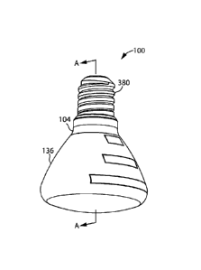
114 to emit from light guide light emitting face 112, or that causes light
emission in
response to light internally striking the light emitting locations 114. In
some
examples, light emitting locations 114 may be spaced apart discontinuities
(e.g.
bumps or divots) or light scattering material that interrupt the internal
reflection of
light within light guide 108, or photoluminescent spots (e.g. fluorescent or
phosphorescent spots) that absorb internally incident light and then emit
light
outwardly.
Unidirectional Light Source
[00325] In accordance with one aspect of this disclosure, which may be
used
with one or more other aspects disclosed herein, a LED light source 100 is
provided
wherein light is inhibited from being emitted in one or more directions.
Accordingly,
in some embodiments, LED light source 100 may preferentially emit light in
particular directions. For example, LED light source 100 may preferentially
emit
light in light emitting directions 120, and emit substantially no light in non-
light
emitting directions 124. An advantage of this design is that it allows the
light emitted
by the LED light source 100 to be concentrated towards a subject to be
illuminated.
[00326] In one embodiment, light may not be emitted from a rear
surface.
Accordingly, as exemplified, light guide 108 may have a rear face 128 opposed
to
light emitting face 112, and an opaque member, which may have a reflective
surface, such as reflector 132, may overlie rear face 128. Reflector 132 may
reflect
light emitted from light guide rear face 128. For example, an LED light source
100
may be suspended from a ceiling to illuminate a room, and have a reflector 132
that
prevents the LED light source 100 from illuminating the ceiling. Reflector 132
may
also improve the power efficiency of LED light source 100 by intensifying the
light
directed in light emitting directions 120.
[00327] Reflector 132 has a reflective surface 134 that faces light
guide rear
face 128 to reflect light escaping light guide rear face 128. Reflective
surface 134
can be made of any reflective material. In some embodiments, reflective
surface
134 includes a white coating. An advantage of this design is that it allows
reflector
132 to provide a neutral reflection with little or no effect on the color of
the reflected
light. In some embodiments, reflective surface 134 is coated with a highly
reflective
-28 -
Date Recue/Date Received 2023-08-23
coating (e.g. greater than 90% reflectivity), such as titanium oxide. This can
reduce
light attenuation at the point of reflection to improve the efficiency of the
LED light
source 100. As shown in FIG. 4, reflector 132 may be positioned with
reflective
surface 134 abutting light guide rear face 128. This can allow reflector 132
to reflect
all light emitting from light guide rear face 128. In some embodiments,
reflective
surface 134 is in physical contact with light guide rear face 128.
[00328] Returning to FIG. 4, reflector 132 may be a component of
housing
104. For example, reflector 132 may provide a rear wall of housing 104.
Alternatively, reflector 132 may be a discrete component (separate from
housing
104) that is positioned behind light guide rear face 128. In some embodiments,
reflector 132 is a reflective coating (e.g. paint) applied to light guide rear
face 128.
[00329] In some embodiments, LED light source 100 does not include
reflector 132. An advantage of this design is that it allows LED light source
100 to
emit light in more directions, which can be desirable in some cases such as to
simultaneously illuminate a room below and ceiling art above. For example,
light
guide 108 may include light emitting locations 114 on both of faces 112 and
128 so
that light is emitted from both of faces 112 and 128.
Diffuser
[00330] In accordance with another aspect of this disclosure, which
may be
used with one or more other aspects disclosed herein, a LED light source 100
may
be provided with a diffuser to soften the point effect of light emitted from
light
emitting face 112. While the use of light emitting locations 114 on light
emitting face
112 may reduce the point effect of light provided by a LED (as compared with
the
LED facing directly towards the area to be illuminated) a diffuser may provide
a
more even distribution of light.
[00331] Accordingly, as exemplified in FIG. 2, LED light source 100
may
include a light transmitting surface 136 (also referred to herein as a
diffuser) that
overlays light guide 108 to further diffuse and soften the light emitted by
LED light
source 100. Diffuser 136 is at least translucent (i.e. at least semi-
transparent). In
other words, diffuser 136 is not completely opaque. In the illustrated
example, at
least a portion of diffuser 136 is formed as a cover that is spaced apart from
light
guide 108. This can allow the diffuser 136 to be relatively larger in area
than light
guide light emitting face 112, which can thereby enhance the light diffusion
-29 -
Date Recue/Date Received 2023-08-23
capability of diffuser 136. In the illustrated example, diffuser 136 is shown
having
a central panel 138 which is spaced apart from light guide light emitting face
112,
and which extends longitudinally between first and second diffuser ends 142
and
146. Diffuser central panel 138 may be spaced apart from light guide light
emitting
face 112 by any distance sufficient to allow the light from light guide light
emitting
face 112 to disperse over central panel 138. For example, referring to FIG. 4,
diffuser central panel 138 may be spaced apart from light guide light emitting
face
112 by a distance 150 of between about 0.25 to 3 inches.
[00332] Returning to FIG. 2, in some embodiments, diffuser 136 may be
non-
.. planar (e.g. curved or angular) which can further enhance the light
diffusion
capability of diffuser 136 with additional surface area and light emitting
directions
120. In the illustrated embodiment, diffuser 136 includes first and second
sides 154
and 158 including first and second diffuser side panels 162 and 170, each of
which
extends between the first and second diffuser ends 142 and 146. As shown,
first
and second diffuser sides 154 and 158 are oriented at a (non-zero) angle to
diffuser
central panel 138. Together, diffuser central panel 138 and diffuser sides 154
and
158 may form a concave inner diffuser surface 174 that extends over the light
guide
light emitting face 112 and over longitudinally extending light guide sides
178 and
182. An advantage of this design is that it can allow diffuser 136 to capture
and
diffuse light emitted by light guide 108 through face 112 and light that may
escape
through light guide sides 178 and 182.
[00333] Diffuser 136 can be made of any material suitable for
diffusing light
emitted by light guide 108. For example, diffuser 136 may be made of at least
one
of acrylic, polypropylene, and polycarbonate. In some embodiments, the
diffuser
136 may be white in color. This can reduce or eliminate the effect the
diffuser 136
has on the color of the diffused light. In other embodiments, diffuser 136 may
be
intentionally non-white to provide a desired color effect.
[00334] In alternative embodiments, LED light source 100 may not
include a
diffuser 136 or other member that overlays light guide light emitting face
112. An
advantage of this design is that it allows unfiltered light to be focused on
an object
to be illuminated. A further advantage of this design is that it mitigates the
light
attenuation associated with diffuser 136, and therefore improves the lighting
efficiency of the LED light source 100.
- 30 -
Date Recue/Date Received 2023-08-23
Light Source with a removable LED Cartridge
[00335] In accordance with another aspect of this disclosure, which
may be
used with one or more other aspects disclosed herein, a LED light source is
provided wherein the LEDs are removable so that they may be replaced when,
e.g.,
one or more of the LEDs fails. For example, as exemplified herein, the LED
light
source may removable receive a cartridge 116 which comprises one or more LEDs.
[00336] As exemplified in FIG. 3, cartridge 116 may be removably
receivable
in housing 104. An advantage of this design is that it allows cartridge 116 to
be
removed, for repair or disposal, and replaced. This contrasts with traditional
light
fixtures in which a disposable light tube is removably connected to a ceiling
ballast.
The light tube includes not only an LED or fluorescent lighting module but
also a
diffusing covering, and other components. LED light source 100 provides a
reusable light guide 108 (FIG. 2) and optional diffuser 136 which need not be
disposed with cartridge 116. As a result, cartridge 116 is smaller, lighter,
less
expensive, and more environmentally friendly than the disposable light tubes
of
traditional light fixtures. Cartridge 116 also provides greater flexibility to
the shape
and physical configuration of LED light source 100 because LED light source
100
need not be designed around accommodating a long cylindrical light tube.
[00337] Cartridge 116 can be removably receivable in housing 104 in
any
manner that allows cartridge 116 to be powered and positioned to emit light
into
light guide 108 (FIG. 2). In the illustrated embodiment, housing 104 includes
a
recess 140 provided on an outer surface of the light source into which
cartridge 116
is slideably receivable. This allows cartridge 116 to be conveniently inserted
and
removed from LED light source 100, without the need to disassemble the light
source which can be particularly significant where LED light source 100 is
positioned in difficult-to-reach (e.g. high-up) areas or where there are many
(e.g.
dozens to thousands) of LED light sources 100 to maintain in a facility (e.g.
an office
building).
[00338] Returning to FIG. 2, light guide 108 extends longitudinally
from a first
end face 144 to a second end face 148. Light guide 108 has a longitudinal
length
152, a transverse width 156, and a thickness 160. As shown in FIGS. 4 and 5,
cartridge 116 may include a plurality of LEDs 164 which are positioned and
oriented
on a first cartridge face 166 that extends transversely to light guide 108 to
emit light
-31 -
Date Recue/Date Received 2023-08-23
into light guide first face 144 when cartridge 116 is received in housing 104.
The
light travels along longitudinal length 152 of light guide 108 and is re-
emitted from
light guide light emitting face 112 at light guide light emitting locations.
An
advantage of this design is that cartridge 116 may be sized according to light
guide
transverse width 156 instead of light guide longitudinal length 152. This
allows
cartridge 116 to be smaller, lighter, and less expensive as compared with
traditional
disposable light tubes that are sized to extend substantially the longitudinal
length
of the light fixture.
[00339] As exemplified in FIGS. 4 and 5, cartridge 116 may be slideably
receivable in housing recess 140. As shown, housing recess 140 may extend from
an insertion end 168 transversely of light guide 108 to an inner end 172, and
from
a first side 176 longitudinally away from light guide 108 to an opposed face
180.
Housing recess insertion end 168 may define an insertion opening 184 sized to
receive cartridge 116. In use, cartridge 116 may be moved transversely
relative to
the longitudinal length 152 of the light guide 108 from an insertion position
(FIG. 6)
to an inserted position (FIG. 5) and vice versa. As shown in FIG. 4, in the
inserted
position, light guide first end face 144 and cartridge first face 166 abut
housing
recess first side 176 and face each other so that LEDs 164 are oriented and
positioned to emit light into light guide 108. As shown in FIG. 6, in the
insertion
position, cartridge first face 166 is at least partially spaced apart from
housing
recess first side 176. From the insertion position (FIG. 6), cartridge 116 can
be
moved longitudinally towards light guide 108 to the inserted position (FIG.
5), or
withdrawn from the housing 104 transversely through the housing insertion
opening
184 as seen in FIG. 7. It will be appreciated that, in the inserted position,
the LEDs
or the face of cartridge 116 facing the light guide may contact the face of
the light
guide. Alternately, they may be spaced apart.
[00340] Returning to FIGS. 4 and 5, housing 104 may be configured to
retain
cartridge 116 in the inserted position, whereby LEDs 164 are positioned in
close
proximity to light guide first end face 144 for efficient transmission of
light from LEDs
164 into light guide 108. In some embodiments, when cartridge 116 is in the
insertion position (FIG. 6), housing 104 may bias cartridge 116 to move to the
inserted position (FIG. 5). For example, housing 104 may include a biasing
member
188 that urges cartridge 116 to move from the insertion position to the
inserted
position. An advantage of this design is that it allows the housing recess 140
to
- 32 -
Date Recue/Date Received 2023-08-23
provide greater clearance for easy insertion of the cartridge 116 into housing
recess
140. For example, housing recess opening 184 may have a longitudinal width 192
that is substantially wider than the corresponding dimension 196 of cartridge
116,
and biasing member 188 may be relied upon to move cartridge 116 toward housing
recess first side 176, away from housing recess opposed face 180, to close the
gap
between LEDs 164 and light guide first end face 144.
[00341] Referring to FIGS. 4 and 7, in some embodiments, housing
recess
140 may narrow in longitudinal width between housing recess insertion opening
184
and housing recess inner end 172. An advantage of this design is that allows
for a
wide housing recess insertion opening 184 for easy insertion of cartridge 116,
and
also guides cartridge 116 to move toward the inserted position as the
cartridge 116
is moved inwardly. In the illustrated example, the narrowing width of housing
recess
140 is effected by a cam 204 that defines a portion of housing recess opposed
face
180 and that rises towards housing recess first side 176 between housing
recess
insertion opening 184 and housing recess inner end 172. It will be appreciated
that
cartridge 116 may be moved manually into the inserted position shown in FIG. 5
or
alternately a drive member, as discussed hereinafter, may be used.
[00342] As exemplified in FIGS. 5 and 6, cartridge 116 may be
prevented from
being withdrawn from housing recess 140 when in the inserted position.
Instead, it
may be required to move cartridge 116 to the insertion position to release
cartridge
116 from housing recess 140. An advantage of this design is that cartridge 116
is
prevented from accidental withdrawal. Biasing member 188 may retain cartridge
116 in the inserted position, whereby withdrawal of cartridge 116 is
prevented, until
a deliberate action (e.g. manual user action) is taken to move cartridge 116
to the
insertion position. In the insertion position, cartridge 116 can be freely
withdrawn.
[00343] Cartridge 116 may be prevented from withdrawal when in the
inserted
position, in any manner. For example, each of housing 104 and cartridge 116
may
include a locking member 208, 212. Locking members 208 and 212 can be any
components which interact when cartridge 116 is in the inserted position to
inhibit
withdrawal of cartridge 116 from housing recess 140. As exemplified, locking
members 208 and 212 may include faces that abut in the inserted position to
obstruct withdrawal of cartridge 116 from housing recess 140. In the
illustrated
example, housing locking member 208 is formed as a protrusion including an
inner
end face 216, cartridge locking member 212 is formed as a slot including an
inner
- 33 -
Date Recue/Date Received 2023-08-23
end face 218, and end faces 216 and 218 abut when housing locking member 208
is received in cartridge locking member 208 in the inserted position (FIG. 5)
to
prevent withdrawal of cartridge 116 from housing recess 140.
[00344] Referring to FIGS. 5 and 6, biasing member 188 can take any
form
that urges cartridge 116 from the insertion position to the inserted position.
In the
illustrated embodiment, biasing member 188 is an electrical contact that
supplies
electricity from a power source (e.g. an electrical wire 214 connected to an
energy
storage member or an electrical wall plug) to cartridge 116 for powering LEDs
164.
An advantage of this design is that the biasing member 188 performs double
duty
as a biasing member and electrical conductor thereby avoiding the complexity,
weight, and expense of having a separate component act as a biasing member.
[00345] Still referring to FIGS. 5 and 6, biasing member 188 can apply
a
biasing force to any portion of cartridge 116 that is suitable for urging
cartridge 116
to the inserted position (FIG. 5). In the illustrated embodiment, biasing
member 188
is positioned in housing recess 140 proximate housing recess inner end 172 to
apply a biasing force to an inner end portion 216 of cartridge 116. An
advantage of
this design is that biasing member 188 does not act upon cartridge 116 until
cartridge 116 is moved into the insertion position within housing recess 140.
This
allows LEDs 164 to align with light guide first end face 144 (FIG. 4) before
biasing
member 188 urges cartridge 116 into the inserted position, for example.
[00346] In the illustrated example, cartridge 116 is substantially
rigid. For
example, cartridge 116 may include a rigid substrate 220 (e.g. a printed
circuit
board) that defines cartridge first face 166, on which LEDs 164 are arranged.
As
shown, biasing member 188 may urge cartridge first face 166 to lay flat
against
housing recess first side 176. As a result, cartridge 116 is urged to rotate
about
cartridge inner end portion 216 towards housing recess first side 176 (and
light
guide first end face 144, FIG. 4). Thus, the rigidity of cartridge 116 may
cooperate
with biasing member 188 to move cartridge 116 into the inserted position (FIG.
5)
by application of the biasing force to cartridge inner end portion 216.
Referring to
FIG. 6, it can be seen that housing recess cam 204 helps to guide cartridge
inner
end portion 216 into engagement with biasing member 188. This helps to prevent
misalignment of cartridge 116 when it is inserted into housing recess 140.
- 34 -
Date Recue/Date Received 2023-08-23
[00347] Referring to FIGS. 3 and 4, LED light source 100 can include
any
housing 104 suitable for holding light guide 108 and cartridge 116, and
optionally
hold one or both of a reflector 132 and a diffuser 136. For example, housing
104
may hold these components in relative positions that allow for efficient
transmission
and distribution of light from cartridge LEDs 164 to light emitting directions
120. In
the illustrated example, housing 104 includes first and second end members 224
(FIG.1). Each housing end member 224 may include a light guide retention slot
228 sized to receive an end portion 232 of light guide 108. In the illustrated
example, retention slot 228 is sized to receive light guide end portion 232
and a
reflector end portion 236. An advantage of this design is that it allows
housing 104
to hold reflector 132 against light guide 108 for efficient light reflection.
In the
illustrated example, housing end member 224 includes a transversely extending
sidewall 240 and a transversely extending inner wall 250, which are spaced
apart
to define retention slot 228.
[00348] Referring to FIG. 2, LED light source 100 can include any number of
cartridges 116. For example, LED light source 100 may include a cartridge 116
removably receivable in each of the housing end members 224. An advantage of
this design is that it allows cartridges 116 to emit light into both light
guide end faces
144 and 148, which may help to more evenly distribute light emitted from light
guide
light emitting face 112, and reduce the average number of internal reflections
in
light guide 108 for greater light transmission efficiency. In other
embodiments, LED
light source 100 includes just one cartridge 116 that is removably receivable
in just
one of housing end members 224. An advantage of this design is that LED light
source 100 has only one cartridge 116 to replace which can reduce replacement
time and maintenance costs considerably in environments that have hundreds or
thousands of LED light sources 100 installed (e.g. office buildings).
[00349] Turning to FIG. 3, housing end member 224 may include an end
wall
248 that defines housing recess opposed face 180. As shown, housing end wall
248 may be connected to housing sidewall 240 in opposition to retention slot
228.
Housing end wall 248 may include housing recess cam 204 and biasing member
188. Housing end wall 248 may be integrally formed with housing sidewall 240,
or
discretely formed as shown and then permanently or removably connected to
housing sidewall 240. In the illustrated example, housing end wall 248 is
connected
to housing sidewall 240 with fasteners 252 (e.g., screws).
- 35 -
Date Recue/Date Received 2023-08-23
[00350] In several of the examples, the housing recess 140 is
illustrated as
having a housing insertion opening 184 on a lateral side of housing sidewall
240,
which allows cartridge 116 to be inserted and removed in a transverse
direction
parallel to light guide light emitting face 112. However, it will be
appreciated that
housing insertion opening 184 may be positioned elsewhere on housing sidewall
240 and that cartridge 116 may be insertable in different directions. The
position of
housing insertion opening 184 and cartridge insertion direction may be
selected
based on, for example the orientation of the LED light source 100 when
installed.
For example, in some applications it may be preferable to position housing
insertion
opening 184 for easiest user accessibility (for removing or inserting
cartridge 116)
or alternatively to conceal cartridge 116 (for aesthetics or to avoid
tampering).
[00351] As exemplified in FIGS. 42-46, insertion opening 184 may be
positioned on an upper side 368 of housing sidewall 240. As shown, cartridge
116
is moveable from an inserted position (FIG. 44) to an insertion position (FIG.
45),
and then withdrawable through housing insertion opening 184 in a direction
normal
to light guide light emitting face 112.
Heat Sink
[00352] In accordance with another aspect of this disclosure, which
may be
used with one or more other aspects disclosed herein, a heat sink may be
provided
to assist in withdrawing head produced by the LEDs. As exemplified in FIG. 7,
the
LED light source may include a heat sink 256 thermally connected to cartridge
substrate 220. The heat sink may be part of the cartridge 116 (see for example
the
embodiment of FIG. 7) or, alternately, it may be thermally connected to the
cartridge
116 when the cartridge 116 is in the inserted position (e.g., it may abut the
cartridge
116 when cartridge 116 is in the inserted position). Heat sink 256 can have
any
design suitable for dissipating heat generated by cartridge 116, and in
particular
LEDs 164. In the illustrated example, heat sink 256 is thermally connected to
cartridge second face 260, which is opposed to cartridge first face 166. As
shown,
heat sink 256 may have a plurality of fins extending away from cartridge
substrate
220 to increase convective surface area for efficient heat dissipation.
[00353] In the illustrated embodiment, cartridge 116 includes heat
sink 256,
such that heat sink 256 is removable from housing 104 with cartridge 116, and
optionally disposable with cartridge 116. For example, heat sink 256 may be
- 36 -
Date Recue/Date Received 2023-08-23
integrally formed with cartridge 116, or discretely formed and permanently or
removably attached to cartridge 116. An advantage of including heat sink 256
in
cartridge 116 is that it may promote better thermal contact between heat sink
256
and substrate 220 which can lead to better thermal conduction. This thermal
contact may be improved by interposing thermal compound (e.g. high thermal
conductivity paste or gel) between heat sink 256 and substrate 220. By
allowing
heat sink 256 to be disposable with cartridge 116, the user may avoid having
to
ensure proper thermal contact or reapply thermal compound between heat sink
256
and substrate 220.
[00354] Referring to FIG. 8, heat sink 256 may be a separate component from
cartridge 116 in some embodiments. For example, heat sink 256 may be a
component of housing 104. Cartridge 116 may be free of heat sinks. An
advantage
of this design is that heat sink 256 may be a reusable non-disposable
component
that is retained with housing 104 as cartridge 116 is removed and replaced.
This
further reduces number of components in disposable cartridge 116, which can
make cartridge 116 less expensive, smaller, and lighter (and consequently less
expensive to ship and easier to store). Turning to FIGS. 9-11, cartridge 116
makes
thermal contact with heat sink 256 in the inserted position (FIG. 9), and is
thermally
disconnected and physically separated from heat sink 256 when removed from
housing 104 (FIG. 11).
[00355] Referring to FIGS. 9-12, heat sink 256 may be urged into
physical
contact with cartridge 116 as cartridge 116 is biased into the inserted
position
(FIGS. 9 and 12). An advantage of this design is that the pressure at the
interface
of cartridge 116 and heat sink 256 can collapse small particles (e.g. dust or
dirt),
and thereby promote better thermal contact between cartridge 116 and heat sink
256. As exemplified, cartridge substrate 220 and heat sink 256 have
complimentary
faces 260 and 264, which make flush physical contact when cartridge 116 is in
the
inserted position (FIGS. 9 and 12). Faces 260 and 264 can have any
complimentary surface profiles that promote efficient heat transfer when in
flush
physical contact. In the illustrated example, cartridge substrate face 260 and
heat
sink face 264 are flat planar surfaces.
[00356] Optionally, one or both of faces 260 and 264 includes thermal
compound that accommodate surface defects to enhance the thermal contact. In
some embodiments, the thermal compound is pre-applied to cartridge substrate
- 37 -
Date Recue/Date Received 2023-08-23
face 260 (e.g. in the retail package). An advantage of this design is that the
user is
not required to apply the thermal compound, which avoids potential
complications
associated with misapplication of the thermal compound. In other embodiments,
the thermal compound is user applied to heat sink face 264. An advantage of
this
design is that the cartridge 116 can be provided free of thermal compound, and
therefore at a lower weight and cost. Manufacturing and packaging of cartridge
116
are also simplified. Also, the thermal compound applied to heat sink face 264
may
remain effective for use in connection with several cartridges 116 before
reapplication is required, such that less thermal compound may used overall.
[00357] Heat sink 256 can be permanently connected or integrally formed
with
housing 104, or removably connected to housing 104. In
the illustrated
embodiment, heat sink 256 is positioned in housing recess 140. As shown, heat
sink 256 may be connected to housing end wall 248 by biasing members 188b.
Biasing members 188b urge heat sink 256 in the longitudinal direction towards
cartridge 116 to move cartridge 116 from the insertion position (FIG. 10) to
the
inserted position (FIGS. 9 and 12). To remove cartridge 116, the user may
apply
force to cartridge 116 in opposition to biasing members 188 to move cartridge
116
from the inserted position (FIGS. 9 and 12) to the insertion position (FIG.
10), and
then pull cartridge 116 transversely out of housing recess 140 through housing
insertion opening 184 (FIG. 11).
[00358]
Housing 104 can include any number of biasing members 188b,
which can be any type of biasing member suitable for urging heat sink 256
against
cartridge 116. In the illustrated example, housing 104 includes two spaced
apart
biasing members 188b, which as shown may take the form of helical compression
springs. This configuration can allow biasing members 188b to provide
distributed
biasing force against heat sink 256 for more even pressure at the interface of
heat
sink 256 and cartridge 116. In alternative embodiments, housing 104 may
include
just one biasing member 188b, or more than two biasing members 188b. Moreover,
biasing member 188b may take another form, such as a resiliently deformable
pad
for example.
[00359]
Referring to FIG. 8, in some embodiments, housing end wall 248 may
be removably connected or movably connected (e.g. pivotally connected) to
housing 104. An advantage of this design is that it can provide access to heat
sink
256 (e.g. for repair or replacement of heat sink 256, or for application of
thermal
- 38 -
Date Recue/Date Received 2023-08-23
compound to heat sink 256). Housing end wall 248 can be removable connected
or movably connected to housing 104 in any manner. For example, housing end
wall fasteners 252 may be removable to release housing end wall 248 from
housing
104.
Driving Member
[00360] In accordance with another aspect of this disclosure, which
may be
used with one or more other aspects disclosed herein, a driving member may be
provided to assist in moving, or to move, the cartridge to the inserted
position. As
exemplified in FIGS. 13A and 13B, driving member 268 may be movably mounted
in housing 104, and operable to drive cartridge 116 from the insertion
position to
the inserted position. The driving member 268 can drive a heat sink 256
against
cartridge 116 as shown, or can drive a cartridge 116 including an integrated
heat
sink.
[00361] Referring to FIGS. 14-16, driving member 268 may be movable
between a first position (FIG. 14) in which the driving member 268 acts to
drive and
retain cartridge 116 in the inserted position (FIG. 14), and a second position
(FIGS.
15-16) in which driving member 268 releases cartridge 116 from the inserted
position, whereby cartridge 116 can move to the insertion position (FIG. 15)
and
then be withdrawn from housing recess 140 (FIG. 16).
[00362] Referring to FIGS. 13B and 14, driving member 268 can have any
construction suitable for selectively driving cartridge 116 between the
insertion
position and the inserted position. In the illustrated embodiment, driving
member
268 is formed as a movable shaft having an inner end 272 pivotally mounted to
housing 104. Driving member 268 may also have an outer end 276 which protrudes
from housing 104, and provides a handle fora user to grasp to manually move
the
driving member 268 between its first and second positions. As shown, a driving
cam 280 may be positioned between the driving member 268 and the cartridge
116.
Driving cam 280 may include a cam surface 284 that interacts with driving
member
268 as driving member 268 moves to the first position, whereby the driving cam
280
is moved longitudinally to drive cartridge 116 to the inserted position.
[00363] Driving member inner end 272 may be pivotally connected to
housing
104 in any manner. In the illustrated embodiment, driving member inner end 272
and housing 104 form a ball and socket joint. In other embodiments, driving
- 39 -
Date Recue/Date Received 2023-08-23
member inner and 272 and housing 104 may form another type of pivotal
connection, such as a hinged joint.
[00364] Cam
surface 284 can have any configuration that allows driving
member 268 to move driving cam 280 towards cartridge 116 as driving cam 280 is
moved to the first position (FIG. 14). In the illustrated embodiment, cam
surface
284 is planar and sloped relative to vertical and horizontal, and driving
member 268
is vertically movable between the second and first positions. Driving member
268
rides along cam surface 284 as driving member 268 is moved upwardly to the
first
position, which causes driving cam 280 to slide longitudinally towards
cartridge 116.
In other embodiments, cam surface 284 may be non-planar, which may provide a
different movement profile.
[00365] As
shown, heat sink 256 may be connected to housing 104 and
positioned between driving cam 280 and cartridge 116. In this embodiment,
moving
driving member 268 to the first position (FIG. 14) drives driving cam 280 and
heat
sink 256 against cartridge 116, thereby urging cartridge 116 to move to the
inserted
position. The pressure that forms at the interface of heat sink 256 and
cartridge
116 may help to improve thermal contact between them. In
alternative
embodiments, cartridge 116 includes heat sink 256, or LED light source 100
includes no heat sink.
[00366] Referring to FIGS. 13A-16, LED light source 100 may include one or
more biasing members 288, which act against driving member 268 to retract
driving
cam 280 when driving member 268 is in the second position (FIG. 15). An
advantage of this design is that it allows cartridge 116 to be easily removed
(FIG.
16) once driving member 268 is moved to the second position. Biasing member
288 can have any configuration suitable for urging driving cam 280 away from
cartridge 116 when driving member 268 is moved to the second position (FIG.
15).
In the illustrated example, housing 104 includes two spaced apart biasing
members
288, formed as tensile springs, which are connected to heat sink 256 and
housing
end wall 248. As shown, when driving member 268 is moved to the second
position
(FIG. 15), biasing members 288 pull heat sink 256, along with driving cam 280,
longitudinally towards housing end wall 248 away from cartridge 116. This
provides
clearance for cartridge 116 to move longitudinally to the insertion position
(FIG. 15),
and then removed from housing 104 (FIG. 16).
- 40 -
Date Recue/Date Received 2023-08-23
[00367] Referring to FIGS. 13A and 16, housing 104 may include one or
more
retention members 292 that act to retain driving member 268 in the first or
second
positions. For example, retention members 292 may retain driving member 268 in
position against the force of gravity or biasing members. Retention members
292
can have any configuration suitable for retaining driving member 268 in
position. In
the illustrated embodiment, driving member outer end 276 extends through a
guide
slot 296. The guide slot may guide and constrain the movement of driving cam
280
(FIG. 13B) to a path between the first position (FIG. 13A) and the second
position
(FIG. 16). As shown, guide slot 296 may include retention members 292 formed
as
inward protrusions, which narrow a small portion of guide slot 296. Driving
member
268 can be moved along guide slot 296 past the retention members 292 into or
out
of the first or second position with a bit of force. Consequently, retention
members
292 impede driving member 268 from moving out of the first or second positions
until a user deliberately applies sufficient force to move driving member 268
past
the retention member 292.
[00368] Reference is now made to FIGS. 17-19. In alternative
embodiments
driving member 268 may be slideably mounted to housing 104. Driving member
268 may be slideably mounted to housing 104 in any manner that allows driving
member 268 to move between the first and second positions. In the illustrated
example, housing 104 includes a track 304, and driving member inner end 272 is
slideably mounted to track 304 for movement between the first position (FIG.
18)
and the second position (FIG. 19).
[00369] Reference is now made to FIGS. 20-22. In some embodiments,
driving member 268 is rotationally mounted to housing 104. For example,
driving
member 268 may be rotated (e.g. around an axis 308 of driving member 268) to
drive cartridge to the inserted position. In the illustrated example, driving
member
inner end 272 is rotatably connected to housing 104, and driving member 268 is
rigidly connected to driving cam 280, such that they rotate together.
[00370] Driving cam 280 can have any shape that can drive cartridge
116
towards the inserted position (FIG. 22) when driving cam 280 is rotated to a
particular rotary position. For example, driving cam 280 may have a cross-
sectional
shape normal to rotary axis 308 that is either non-circular (e.g. oblong), or
non-
centered on rotary axis 308, or both. Consequently, the distance between cam
surface 284 and housing recess 140 changes as driving cam 280 is rotated. In
the
-41 -
Date Recue/Date Received 2023-08-23
illustrated example, driving cam 280 has an oblong cross-sectional shape
centered
on rotary axis 308. As shown in FIGS. 23-26, driving cam 280 can rotate (by
rotating
driving member 268) between a first position (FIG. 23) in which driving cam
280
drives cartridge into the inserted position, through an intermediate position
(FIG.
24), to a second position (FIG. 25) in which driving cam 280 releases
cartridge 116
from the inserted position. In the second position, cartridge 116 is free to
move to
the insertion position (FIG. 25), and then be removed from the housing 104
(FIG.
26).
[00371] Turning to FIG. 22, driving member outer end 276 may extend
through
an opening 312 in housing 104 to provide user accessibility to manipulate
driving
member outer end 276 for rotating driving member 268 about driving member axis
308. In the illustrated embodiment, housing 104 includes a retention member
292
that acts to resist rotation of driving member 268 from the first position to
the second
position. As shown, retention member 292 may be a protrusion from housing 104
that makes contact with a protrusion 312 on driving member 268 to resist
rotation
of driving member 268 to the second position. When in the first position, the
user
may deliberately apply a force to driving member outer end 276 that overcomes
the
resistance by retention member 292 to rotate driving member 268 to the second
position (and vice versa). Thus, retention member 292 may retain driving
member
268 in the first position against, e.g. the force of biasing members 288 (FIG.
21) or
resilient compressibility of cartridge 116.
[00372] Reference is now made to FIGS. 27-29. In some embodiments,
driving member 268 includes a toggle joint 316. As shown, toggle joint 316 may
include first and second pivotally connected arms 320. Driving member 268 may
also include an arm 324 that extends from toggle joint 316, and that is
manually
user operable to articulate the toggle joint 316.
[00373] Referring to FIGS. 29-32, driving member 268 is movable between
a
first position (FIGS. 29 and 30) in which driving member 268 drives cartridge
116 to
the inserted position, and a second position (FIG. 31) in which driving member
268
releases cartridge 116 from the inserted position, which allows cartridge 116
to be
moved to the insertion position and then withdrawn from housing 104 (FIG. 32).
As
shown, moving driving member 268 between the first position (FIGS. 29 and 30)
and the second position (FIG. 31) includes articulating the toggle joint 316.
Toggle
joint arms 320 are pivotally connected to each other end-to-end, and oriented
so
-42 -
Date Recue/Date Received 2023-08-23
that a longitudinal length 328 of the toggle joint 316 changes as the toggle
joint 316
is articulated (i.e. as the pivotal connection between the toggle joint arms
320 is
articulated). The longitudinal length 328 of toggle joint 316 governs the
longitudinal
separation of cartridge 116 and housing end wall 248, whereby increasing
longitudinal length 328 moves cartridge 116 towards the inserted position.
[00374] In the first position (FIGS. 29 and 30), the toggle joint arms
320 may
be parallel or nearly parallel (e.g. within 15 degrees of parallel). The
longitudinal
length 328 of toggle joint 316 drives the cartridge 116 (and heat sink 256 in
the
example shown) away from housing end wall 248 into the inserted position. In
the
second position (FIG. 31), the toggle joint arms 320 are substantially folded
(i.e.
collapsed) into a V-shape, such that the longitudinal length 328 of toggle
joint 316
is reduced as compared to the first position. This provides the cartridge 116
(and
heat sink 256) with longitudinal clearance to move to the insertion position.
[00375] In some embodiments, moving the driving member 268 between the
first and second positions may include inflecting the toggle joint 316. Toggle
joint
316 may have a maximum longitudinal length 328 at an intermediary position
between the first and second positions. An advantage of this design is that
the
inflection operates to retain the toggle joint 316 in the first position (FIG.
30) until a
deliberate force is applied to overcome the inflection and move the toggle
joint 316
to the second position (FIG. 31). The force required to overcome the
inflection may
be based on a resilient compression or deformation of cartridge 116 or toggle
joint
arms 320 at the point of inflection, or a biasing member 332 for example.
[00376] Still referring to FIGS. 30 and 31, in the illustrated
example, biasing
member 332 is connected to toggle joint 316 and acts to resist longitudinal
lengthening of toggle joint 316. In some embodiments, biasing member 332 may
also bias toggle joint 316 to the second position (FIG. 31). Biasing member
332
can be any biasing device, such as a tensile spring or elastic band for
example.
Openable End Wall
[00377] In accordance with another aspect of this disclosure, which
may be
used with one or more other aspects disclosed herein, the housing 104 may have
an openable end wall to assist in moving the cartridge to the inserted
position. As
exemplified in FIGS. 33-35, housing end wall 248 may be movable (e.g.
removable
or openable) to provide access to housing recess 140 to insert and remove
cartridge
- 43 -
Date Recue/Date Received 2023-08-23
116, and closeable to hold cartridge 116 in the inserted position. In this
regard,
housing end wall 248 may be considered a driving member in that movement of
housing end wall 248 may drive cartridge 116 into the inserted position.
[00378] Housing end wall 248 may be connected to housing 104 in any
manner that allows housing end wall 248 to be moved (e.g. removed or opened)
to
provide access to housing recess 140 for inserting and removing cartridge 116.
For
example, housing end wall 248 may be translatable (e.g. slidably connected to
housing 104), or rotatable (e.g. pivot ably connected to housing 104) while
remaining connected to housing 104, or completely removable from housing 104
as shown. In the illustrated example, housing end wall 248 is removably
connected
to housing 104 by housing end wall fasteners 252.
[00379] Fasteners 252 may be any fastener suitable for removably
connecting
housing end wall 248 to housing 104. Further, housing 104 may include any
number of fasteners 252. In the example shown, fasteners 252 include magnets
336. Each magnet 336 aligns with a magnetically attractable component 338
(e.g.
another magnet or a ferromagnetic component) to form a mating magnetic pair,
which connects housing end wall 248 to housing 104. The mating magnetic pairs
may include a magnet 336 on housing end wall 248 and a magnetically
attractable
component 338 on housing 104, or vice versa. There can be any number of
magnetic pairs. In the illustrated example, there are two magnetic pairs. In
other
embodiments, there may be just one, or greater than two magnet pairs.
[00380] In use, the user may disconnect fasteners 252 to move housing
end
wall 248 to obtain access to cartridge 116 in housing recess 140. For example,
the
user may manually (i.e. by hand) apply a removing force to housing end wall
248,
which overcomes the closure force of magnets 336, to remove housing end wall
248 from housing 104. Cartridge 116 may then be removed for repair or
replacement by a new cartridge.
[00381] Optionally, as exemplified, heat sink 256 may be provided with
a
housing having an openable end wall. In such a case, heat sink 256 may be
connected to housing end wall 248. Heat sink 256 may be permanently connected
to housing end wall 248. Alternatively, heat sink 256 may be removably
connected
to end wall 248. This can allow heat sink 256 to be easily cleaned, repaired,
or
replaced. In other embodiments, heat sink 256 is not connected to housing end
-44 -
Date Recue/Date Received 2023-08-23
wall 248, and instead removably positioned in housing recess 140 after
cartridge
116 is inserted, before housing end wall 248 recloses housing recess 140. In
other
embodiments, cartridge 116 includes a heat sink 256.
[00382] Reference is now made to FIGS. 36-38. In some embodiments, the
housing end wall fastener 252 may be a threaded fastener and housing 104 may
include a threaded receptacle 340 to receive the threaded fastener 252. In
use,
threaded fastener 252 may be aligned with threaded receptacle 340 and rotated
(e.g. using a tool or by hand) to drive the threaded fastener 252 into
threaded
receptacle 340, thereby joining housing end wall 248 to housing 104. In the
reverse
case, threaded fastener 252 may be rotated to withdraw threaded fastener 252
from
threaded receptacle 340, whereby housing end wall 248 can be separated from
housing 104.
[00383] Threaded fastener 252 may be configured to remain connected to
housing end wall 248 when housing end wall 248 is removed from housing 104. An
advantage of this design is that it avoids having to separately handle and
store
threaded fastener 252 and housing end wall 248 while, e.g. cartridge 116 is
removed and replaced. This can be a real convenience where, for example there
are hundreds or thousands of LED light sources 100 to service in a facility.
As
shown, threaded fastener 252 may be connected to housing end wall 248 in any
manner that allows threaded fastener 252 freedom to rotate. In the illustrated
example, housing end wall 248 includes a shoulder 344, which is received in a
groove 346 formed in threaded fastener 252 to rotatably connect threaded
fastener
252 to housing end wall 248.
[00384] Threaded fastener 252 may be rotatable by hand or using a tool
(e.g.
screw driver). An advantage of a hand rotatable threaded fastener 252 is that
no
tool is required. An advantage of a tool rotatable threaded fastener 252 is
that it
can be smaller and more tamper resistant. In the illustrated example, threaded
fastener 252 includes a handgrip 352 which is readily grasped by hand and
torqued
to rotate threaded fastener 252 to tighten or loose threaded fastener 252. It
will be
appreciated that threaded fastener may alternately use a bayonet mount.
[00385] Reference is now made to FIGS. 39-41. In some embodiments,
fasteners 252 may be formed as buckles. An advantage of this design is that
the
buckles 252 may be easily integrally formed (e.g. molded or cast) with housing
end
- 45 -
Date Recue/Date Received 2023-08-23
wall 248, which can reduce the number of components and assembly costs.
Buckles 252 may take any form that is selectively user operable to connect and
disconnect housing end wall 248 and housing 104. In the illustrated example,
each
buckle 252 includes a resiliently flexible spring arm 356 including a hook 360
at a
free end thereof. Housing sidewall 240 includes a recess 364 (e.g. an
aperture) to
receive each hook 360. In use, spring arms 356 are deflected inwardly and
moved
to align hooks 360 with their corresponding recesses 364, and then released to
spring back outwardly whereby hooks 360 insert into recesses 364. In this
state,
buckles 252 connect housing end wall 248 to housing 104. To remove housing end
wall 248 from housing 104, spring arms 356 may be again deflected inwardly to
remove hooks 360 from their corresponding recesses 364, thereby freeing
housing
end wall 248 from connection to housing 104.
Use of Multiple Cartridges
[00386] In accordance with another aspect of this disclosure, which
may be
used with one or more other aspects disclosed herein, a single light source
100
may include a plurality of cartridges 116, which may be the same or different.
FIG.
47 shows an example including one light guide 108, which receives light from
one
cartridge 116 received in one housing recess 140 of one housing end member
224.
However, LED light source 100 can have any number of light guides 108 and any
number of cartridges 116 in these and other embodiments. FIGS. 48-54
illustrate
exemplary configurations of LED light source 100 having a plurality of light
guides
108 and/or a plurality of cartridges 116.
[00387] FIG. 48 exemplifies an embodiment of LED light source 100
including
one light guide 108 and two cartridges 116. As shown, each housing end member
224 may include a housing recess 140, and a cartridge 116 may be receivable in
each housing recess 140 to emit light into the light guide 108. Each cartridge
116
is shown emitting light into a different one of light guide end faces 144 or
148. An
advantage of this design is that it can allow for more even illumination
and/or more
control over the illumination of light guide 108. For example, cartridges 116
may
be substantially identical and illuminate both of light guide end faces 144
and 148
with the same light intensity to provide more even illumination of light guide
108
across its longitudinal length 152. Alternatively, cartridges 116 may be
different
from each other to provide differential lighting intensity across light guide
longitudinal length 152. In the illustrated example, cartridge 1161 has three
LEDs
-46 -
Date Recue/Date Received 2023-08-23
164, and cartridge 1162 has two LEDs 164. All else being equal, this may allow
cartridge 1161 to illuminate light guide end face 144 with greater light
intensity than
the illumination of light guide end face 148 by cartridge 1162. This pattern
of side-
illumination may provide a desired light emission pattern from light guide 108
for
the purpose of illuminating a subject in a desired manner (e.g. for better
readability
or visibility, or more dramatic effect).
[00388] FIG. 49 exemplifies an embodiment of LED light source 100
including
two light guides 108 and two cartridges 116. As shown, housing end member 224
includes a housing recess 140 that holds two cartridges 116. Alternatively,
housing
end member 224 may include two separate recesses 140, each of which holds one
cartridge 116. The light guides 108 are shown extending from opposite
longitudinal
ends 266 and 270 of housing end member 224. Cartridge 1161 and 1162 include
LEDs 164 oriented to shine in opposite longitudinal directions so that
cartridge 1161
emits light into light guide 1081, and cartridge 1162 emits light into light
guide 1082.
An advantage of this design is that cartridges 116 are centralized, which can
simplify cartridges replacement. For example, where LED light source 100 is
mounted high on a ceiling, a ladder may not need to be repositioned to access
both
cartridges 116. Instead, the central location of cartridges 116 in the same
housing
end member 224 may allow both cartridges 116 to be accessed (e.g. for repair
or
replacement) from one ladder position. Also, this design may be more compact
and
simpler to manufacture and assemble in that fewer housing end members 224 may
be required, all else being equal.
[00389] FIG. 50 exemplifies an embodiment of LED light source 100
including
two light guides 108 and four cartridges 116. As shown, housing 104 includes
an
inner end member 2241 between two outer end members 2242 and 2243. The first
light guide 1081 is connected to end members 2241 and 2242, and the second
light
guide 1082 is connected to end members 2241 and 2243. Inner end member 2241
is shown carrying two cartridges 116 which have LEDs 164 oriented to direct
light
in longitudinally opposite directions into light guide end faces 144 or 148,
substantially as described with respect to FIG. 49. Outer end members 2242 and
2243 are shown each carrying a cartridge 116 having LEDs 164 oriented to
direct
light into the light guide end face 144 or 148 of light guides 1081 and 1082
respectively. An advantage of this design is that it provides a central
location in end
member 2241 for two of the cartridges as discussed above with reference to
FIG.
- 47 -
Date Recue/Date Received 2023-08-23
49, and also provides two sided illumination of light guides 108 for more even
illumination and/or more control over the illumination of light guides 108 as
discussed above with reference to FIG. 48. Also as discussed above with
reference
to FIG. 48, cartridges 116 may be identical to one another, or one or more (or
all)
of cartridges 116 may be different. In the illustrated example, cartridges 116
in
inner end member 2241 are shown having five LEDs 164 each, and cartridges 116
in outer end members 2242 and 2243 are shown having three LEDs 164 each.
[00390] As exemplified in FIGS. 51-52, housing 104 may include any
number
light guides 108 connected longitudinally in series by any number of inner end
members 2241. An advantage of this design is that this can allow for a compact
and substantially continuous arrangement of light guides 108, such as for
ceiling-
mounted lighting of a large area room (e.g. office space). There may be one or
two
outer end members 2242 and 2243 as seen in FIG. 51, or these outer end members
may be omitted as in FIG. 52. FIGS. 51-52 illustrate embodiments of LED light
source 100 including three light guides 108. However, in alternative
embodiments,
there may be four or more light guides 108 arranged in series.
[00391] FIG. 51 exemplifies an example where each inner end member 2241
holds a cartridge 116 having LEDs 164 that collectively direct light into one
of the
adjacent light guides 108. Alternatively or in addition, one or more of inner
end
.. members 2241 may contain a plurality of cartridges 116 that together direct
light in
opposite longitudinal directions to illuminate both adjacent light guides 108
as in
FIG. 52. As exemplified, each inner end member 2241 may include two housing
recesses 140 arranged back-to-back to receive cartridges 116 with LEDs 164
oriented to face opposite longitudinal directions.
[00392] As exemplified in FIG. 53, LED light source 100 may include a
plurality
of cartridges 116 which are arranged to emit light into a single light guide
end face
144 or 148. In other words, LED light source 100 may include a many-to-one
relationship of cartridges 116 to illuminated light guide end face 144 or 148.
An
advantage of this design is that it allows one cartridge 116 containing a
subset of
the LEDs 164 which illuminate the end face 144 or 148 to be replaced, instead
of
replacing a cartridge 116 containing all of the LEDs 164 illuminating that end
face
144 or 148. As a result, the number of working LEDs 164 that are removed when
a cartridge 116 is replaced due to one or more failed LEDs 164 may be reduced.
- 48 -
Date Recue/Date Received 2023-08-23
[00393] Any number of cartridges 116 may be positioned to illuminate a
light
guide end face 144 or 148. In the illustrated embodiment, each housing end
member 224 is configured to receive four cartridges 116 that in pairs emit
light into
the same light guide end faces 144 or 148. Cartridges 116 may be positioned
transversely side-by-side as shown, and/or stacked in the thickness dimension
of
light guide 108.
[00394] As exemplified in FIG. 54, an inner end member 2241 holding a
plurality of cartridges 116 may include a heat sink 256 thermally connected to
the
plurality of cartridges 116 to dissipate heat generated by the plurality of
cartridges
116. As shown, the heat sink 256 may be positioned between the cartridges 116.
An advantage of this design is that it allows one heat sink 256 to service a
plurality
of cartridges 116, which can reduce the number of heat sinks 256 in LED light
source 100. As a result, LED light source 100 may be lighter, less expensive,
and
easier to assemble than an LED light source 100 having a discrete heat sink
256
.. for each cartridge 116, all else being equal.
Non-Planar Light Guides
[00395] In accordance with another aspect of this disclosure, which may
be
used with one or more other aspects disclosed herein, the light guide 108 may
have
a light emitting surface 112 that is not planar. For example, the light
emitting face
may be round.
[00396] As exemplified in FIGS. 55-56, LED light source 100 is formed
in the
shape of a typical incandescent lightbulb having an engagement end 380 for
insertion into a light fixture socket. Engagement end 380 may be any type of
bulb
base known in the art for electrical engagement with a light fixture socket.
For
example, engagement end 380 may be a screw base as shown (e.g. a medium
base E27), a twist & lock base (e.g. a lOmm GUI 0), or a pin base (e.g. a 9mm
G9).
Similar to other embodiments, LED light source 100 includes a removable
cartridge
116 that allows many or most components of LED light source 100 to be reused.
[00397] As shown, LED light source 100 may include a diffuser 136, a
light
guide 108, a cartridge 116, a housing 104, and a bulb engagement end 380.
Cartridge 116 is removably mounted to housing 104 to emit light into light
guide first
end face 144, and light guide 108 re-emits the light from light emitting
locations 114
towards diffuser 136 which radiates light outwardly. Cartridge 116 is
electrically
- 49 -
Date Recue/Date Received 2023-08-23
connected (e.g. by wires or wirelessly) to engagement end 380 to power the
cartridge LED(s) 164. Engagement end 380 delivers power to cartridge 116 from
an external power source when connected to a light fixture socket.
[00398] Light guide 108 can take any shape that allows light to
propagate
longitudinally through internal reflection and emit through light emitting
locations
114 on a light emitting face 112. Earlier embodiments of light guide 108 (see,
e.g.
FIG. 2) show a light guide 108 formed as a thin sheet. An advantage of this
design
is that it allows light guide 108 to emit light across a large area light
emitting face
112, which may be desirable for providing even lighting over large rooms (e.g.
offices) for example. FIG. 56 exemplifies an alternative embodiment including
a
light guide 108 formed as a rod. An advantage of this design is that it
provides a
light emitting face 112 facing many directions at once (e.g. 360 degree
coverage).
This can be desirable where LED light source 100 is formed as a lightbulb for
use
in light fixtures designed for lightbulbs that emit light in all directions
(as in a
traditional incandescent lightbulb). In the illustrated embodiment, light
guide 108 is
formed in the shape of a cylindrical rod having a circularly curved light
emitting face
112. In other embodiments, light guide 108 may be formed in the shape of a rod
having a different cross-section, such as triangular, rectangular, oval, or
another
regular or irregular cross-sectional shape, which may be solid or hollow.
[00399] Diffuser 136 can take any shape suitable for receiving and
radiating
light from light guide 108. For example, diffuser 136 may be shaped according
to
any known light bulb shape, such as a standard incandescent light bulb shape
(bulb
shape "A") as shown. In other examples, diffuser 136 may have a bulb shape
with
a North American letter designation, such as A, B, BT, BR, C, CA, CW, CP, E,
ER,
F, G, HK, K, MB, MR, P, PAR, PS, R, S, and T among others. As discussed
previously, diffuser 136 is at least partially translucent, and may be
completely
transparent.
[00400] As exemplified in FIGS. 101-103, LED light source 100 includes
a
diffuser 136 held between two housing end members 224. As show, light
transmitting surface 136 has a substantially rectangular (e.g. square) cross-
sectional shape. FIG. 105 shows another embodiment including a light
transmitting
surface 136 having a substantially circular cross-sectional shape. In other
embodiments, light transmitting surface 136 can have any other regular or
irregular
cross-sectional shape.
- 50 -
Date Recue/Date Received 2023-08-23
[00401] Referring to FIGS. 56 and 57, light guide 108 extends within
diffuser
136 to emit light towards diffuser 136 to be radiated outwardly. Light guide
108 may
be secured within diffuser 136 in any manner. In the illustrated embodiment,
LED
light source 100 includes a light guide mount 384, which connects light guide
108
to diffuser 136. As shown, light guide mount 384 may be connected to diffuser
136
proximate diffuser lower end 388, and hold a lower portion 392 of light guide
108,
whereby an upper portion 396 of light guide 108 extends upwardly away from
light
guide mount 384 into diffuser 136.
[00402] Light guide mount 384 may be secured to diffuser 136 in any
manner.
In the illustrated embodiment, light guide mount 384 is removably secured to
diffuser 136. An advantage of this design is that is allows light guide mount
384 to
be removed to access diffuser 136 for repair or replacement (e.g. replacement
with
a similar to different light guide 108). As shown, light guide mount 384 has
external
threads 398 which are sized to mate with internal threads 404 within light
guide
lower end 388. Alternatively, light guide mount 384 may be removably or
permanently secured to diffuser 136 by a fastener (e.g. screws, bolts, rivets,
hooks
and loops, magnets, snaps), welds, or adhesives.
[00403] Light guide mount 384 can have any configuration suitable for
holding
light guide 108 within diffuser 136. In the illustrated embodiment, light
guide mount
384 includes a recess or aperture 410 which is sized to receive light guide
lower
portion 392 with a press fit. Alternatively or in addition, light guide mount
384 may
be connected to light guide 108 by screws, straps, adhesive, or welds for
example.
In some embodiments, light guide mount 384 may be integrally formed with light
guide 108.
[00404] Still referring to FIGS. 56 and 57, cartridge 116 may be removably
connected to housing 104 in any manner. In the illustrated example, housing
104
includes a housing recess 140 sized to receive cartridge 116. Cartridge 116
may
fit into housing recess 140 with a press fit. Alternatively or in addition,
cartridge 116
may be connected to housing 104 by a releasable fastener (e.g. screws, bolts,
hooks and loops, magnets, or snaps).
[00405] Optionally, a heat sink may be provided. As exemplified,
housing 104
includes a heat sink 256 that is thermally connected to cartridge 116 when
cartridge
116 is connected to housing 104. As discussed previously, heat sink 256 can
have
-51 -
Date Recue/Date Received 2023-08-23
any design suitable for removing heat from cartridge 116. In the example
shown,
heat sink 256 includes a plurality of fins 412 which extend outwardly from
housing
104.
[00406] Housing 104 may be connected to diffuser 136 in any manner
that
holds the LED(s) 164 of cartridge 116 in close proximity (abutting or even in
contact)
with light guide first end face 144. Preferably, housing 104 is removably
connected
to diffuser 136. As exemplified in FIGS. 57-59, removing diffuser 136 can
provide
access to cartridge 116 for repair or replacement. Returning to FIGS. 56-57,
housing 104 may have a removable threaded connection to diffuser 136. For
example, housing 104 may include external threads 416 that are removably
engageable with diffuser threads 404. Alternatively or in addition, housing
104 may
be removably connected to diffuser 136 by another releasable fastener (e.g.
screws, bolts, hooks and loops, magnets, bayonet mount, or snaps).
Controller
[00407] In accordance with another aspect of this disclosure, which may be
used with one or more other aspects disclosed herein, LED light source 100 may
include a controller 420, which is communicatively coupled to cartridge 116.
Controller 420 may provide programmable and/or remote control of one or more
aspects of the light emitted by the light source 100, (e.g., one or more of
the light
intensity, the number of LEDs that are energized, the color of the LEDs that
are
energized, the length of time that the LEDs are energized, the sequence in
which
the LEDs are energized). For example, controller 420 may be electrically
interposed between bulb engagement end 380 and cartridge 116 to control the
electrical power to cartridge 116.
[00408] Controller 420 may be integrated with cartridge 116. Alternatively,
controller 420 may be a discrete component separate from cartridge 116, as
shown
in the illustrated embodiment. An advantage of this design is that it allows
controller
420 to be reused as cartridge 116 is replaced, and allows controller 420 to be
shielded from heat that cartridge 116 may generate. For example, a heat shield
424 formed of heat insulating material may be positioned between cartridge 116
and controller 420 to shield controller 420 from heat generated by cartridge
116.
Heat shield 424 may be made of any thermally insulating material suitable for
- 52 -
Date Recue/Date Received 2023-08-23
shielding controller 420 from the heat generated by cartridge 116 (e.g. having
a
thermal conductivity of less than 1 W/mK at 20 C).
[00409] FIGS. 58, 59, and 57 illustrate a method of removing cartridge
116
from LED light source 100, such as for repair or replacement. As shown,
diffuser
136 may be disconnected from housing 104 to expose cartridge 116, and then
cartridge 116 may be removed from housing 104 and optionally replaced with a
new
or repaired cartridge 116.
FIGS. 60-62 illustrate an alternate method of removing cartridge 116. In the
illustrated embodiment, LED light source 100 is formed as a light bulb
including a
bulb engagement end 380 and a housing 104. The housing 104 includes a diffuser
136 (also referred to as a light transmitting surface), and defines an
interior 428. A
cartridge 116 is receivable in the housing interior 428, and removable such as
for
repair or replacement. As exemplified, housing 104 includes a housing recess
140
having an insertion end 168 for inserting and removing cartridge 116 and light
guide
108. When cartridge 116 and light guide 108 are inserted into housing recess
140,
cartridge 116 is electrically connected to bulb engagement end 380 to receive
power from a light fixture socket, and LED(s) 164 of cartridge 116 are
oriented to
emit light into light guide end face 144.
[00410] It will be appreciated that, in any embodiment, cartridge 116
and light
guide 108 may together form a disposable and replaceable unitary component of
LED light source 100. An advantage of this design is that it allows cartridge
116 to
be well aligned and permanently connected to light guide 108, ensuring
efficient
transmission of light from cartridge 116 into light guide 108. Alternatively,
cartridge
116 may be separable from light guide 108 so that light guide 108 can be
reused in
connection with many cartridges 116. An advantage of this design is that it
allows
more of LED light source 100 to be reused and less of LED light source 100 to
be
disposed, thus decreasing the cost of operating LED light source 100 and
decreasing the size, weight, and environmental impact of the disposable
components of LED light source 100.
[00411] Still referring to FIGS. 60-62, recess insertion opening 184 may be
positioned anywhere proximate an outer surface of LED light source 100 that
allows
for user access to remove and replace cartridge 116. In the illustrated
example,
insertion opening 184 is provided on diffuser 136. An advantage of this design
is
- 53 -
Date Recue/Date Received 2023-08-23
that it provides user access to insertion opening 184 to remove and replace
cartridge 116 while bulb engagement end 380 remains inserted in a light
fixture
socket. Reference is now made to FIGS. 63-65. In alternative embodiments,
insertion opening 184 is provided on bulb engagement end 380. An advantage of
this design is that cartridge 116 is prevented from being removed
(accidentally or
intentionally) while bulb engagement end 380 is inserted in a light fixture
socket.
This may be an important consideration in some environments, such as factories
with heavy machinery that produce vibrations that may cause a cartridge to
fall out.
Also, this design allows diffuser 136 to have a contiguous outer surface
without
openings or holes that can allow dirt or liquids to enter. This may be
advantageous
for outdoor uses of LED light source 100.
[00412] Recess 140 can have any shape suitable for receiving light
guide 108
and cartridge 116. FIGS. 60-65 illustrate embodiments having rod shaped light
guides 108, including a cylindrical light guide 108 (FIGS. 60-62), and a
square
cross-section light guide (FIGS. 63-65). Recess 140 may be a bore hole in LED
light source 100 shaped to correspond with light guide 108. For example, FIGS.
60-62 show a cylindrical recess 140, and FIGS. 63-65 show a square cross-
section
recess 140.
[00413] Referring to FIGS. 60-62, light guide second end face 148 may
define
a portion of LED light source outer surface 432 when inserted in recess 140.
An
advantage of this design is that it can allow easy access to remove light
guide 108
to access cartridge 116 for repair or replacement. FIGS. 66-68 illustrate an
alternative embodiment where LED light source 100 includes an end cap 440 that
closes light guide 108 and cartridge 116 within recess 140, and which defines
a
portion of the LED light source outer surface 432. An advantage of this design
is
that end cap 440 may allow for better control over the character of the light
emitted
through light guide second end face 148. For example, end cap 440 may be
constructed with similar or identical light transmission properties as
diffuser 136
(diffusivity, color, etc.) such that light emitted from light guide second end
face 148
through end cap 440 is characteristically similar to light emitted by light
guide light
emitting face 112 through diffuser 136.
[00414] Cartridge 116 may be positioned anywhere within recess 140
that
allows cartridge LEDs 164 to emit light into a light guide end face 144 or
148. FIGS.
60-62 show an example in which cartridge 116 is positioned at recess inner end
- 54 -
Date Recue/Date Received 2023-08-23
172 proximate bulb engagement end 380. An advantage of this design is that it
shortens the electrical connection distance between cartridge 116 and bulb
engagement end 380, which may simplify the electrical wiring within LED light
source 100. FIGS. 66-68 exemplify an alternate example in which cartridge 116
is
positioned proximate recess insertion end 168 when inserted in recess 140. As
shown, light guide 108 is positioned inwardly of cartridge 116. An advantage
of this
design is that it can allow access to cartridge 116 (e.g. for repair or
replacement)
without having to remove light guide 108.
[00415] FIGS. 69-71 illustrate another embodiment including a first
cartridge
1161 positioned proximate recess inner end 172, a second cartridge 1162
positioned
proximate recess insertion end 168, and a light guide 108 positioned between
the
first and second cartridges 1161 and 1162. Cartridge 1161 emits light into
light guide
first end face 144, and cartridge 1162 emits light into light guide second end
face
148. An advantage of this design is that it allows for relatively greater and
more
even or controlled illumination of light guide 108. Cartridges 1161 and 1162
may be
permanently connected to light guide 108, and disposable with light guide 108.
Alternatively, cartridges 1161 and 1162 may be separable from light guide 108
so
that light guide 108 can be reused with new or repaired cartridges 116.
Direct Emission of Light from an LED
[00416] In accordance with another aspect of this disclosure, which may be
used with one or more other aspects disclosed herein, a light guide 108 may
not be
used. Instead, as exemplified in FIGS. 72-74, LED light source 100 may not
include
alight guide 108. An advantage of this design is that the light attenuation,
cost, and
complexity associated with including a light guide 108 is mitigated. In the
illustrated
example, cartridge 116 is removably connected to housing 104 beneath a
diffuser
136. As shown, diffuser 136 may be removable to provide access to remove or
replace cartridge 116.
[00417] Diffuser 136 can have any shape suitable for radiating light
from
cartridge 116 onto a subject to be illuminated. In the illustrated embodiment,
diffuser 136 is dome-shaped, such that LED light source 100 has the shape of a
typical incandescent light bulb. FIGS. 75-77 illustrate an alternate
embodiment
where diffuser 136 is substantially flat (e.g. planar), such that LED light
source 100
- 55 -
Date Recue/Date Received 2023-08-23
has the shape of a halogen light bulb. As shown, housing 104 includes a recess
140 to accommodate cartridge 116 beneath the flat diffuser 136.
[00418] Reference is now made to FIGS. 78-80. As shown, LED light
source
100 may include a cartridge 116, containing a plurality of LEDs 164, which is
removably receivable in housing interior 428. As shown, LED light source 100
may
be free of light guides in some embodiments. Instead, cartridge 116 may emit
light
directly towards light transmitting surface 136. An advantage of this design
is that
it may reduce light attenuation associated with light transmission through a
light
guide.
[00419] LEDs 164 may be provided on any one or more faces of cartridge 116.
In the illustrated embodiment, LEDs 164 are provided on a plurality faces,
namely
opposed cartridge faces 166 and 260. An advantage of this design is that it
allows
LEDs 164 to emit light in opposite directions, and thereby better illuminate
light
transmitting surface 136, which radiates the light onto the subject to be
illuminated.
[00420] Each cartridge face 166 and 260 may include any number of LEDs
164 arranged in any configuration. In the illustrated embodiment, LEDs 164 are
distributed and spaced apart longitudinally along the bulb axis 444. An
advantage
of this design is that it allows cartridge 116 to have a narrower width 448,
and
therefore require a smaller insertion opening 184 to be formed in light
transmitting
surface 136.
[00421] FIGS. 81-83 illustrate an embodiment of LED light source 100
similar
to FIGS. 75-77, except, for example that LED light source 100 has the shape of
a
halogen light bulb. Also, housing 104 is shown including a heat sink 256. As
shown, heat sink 256 may define an outer surface of housing 104 and may
encircle
cartridge 116 when cartridge 116 is received in housing interior 428. An
advantage
of this design is that it may provide an enlarged area heat sink 256, which
can allow
heat produced by cartridge 116 to be dissipated more efficiently.
[00422] Reference is now made to FIGS. 84-86. In some embodiment,
cartridge 116 may not include an end cap 440. As shown, this can substantially
reduce cartridge width 448, and consequently allow recess width 192 and
insertion
opening width 452 to be narrowed. As a result, light transmitting surface 136
may
have a greater surface area, all else being equal.
- 56 -
Date Recue/Date Received 2023-08-23
[00423] In some embodiment, cartridge outer end portion 456 may extend
outboard of light transmitting surface 136. An advantage of this design is
that
cartridge 116 may be more easily grasped by hand for removal and replacement.
In other embodiments, cartridge 116 is wholly positioned within housing 104.
[00424] Reference is now made to FIGS. 87-89. In some embodiments, LED
light source 100 may accommodate a plurality of cartridges 116 within housing
104.
An advantage of this design is that it may allow just one cartridge 116
containing a
subset of the LED light source's LEDs 164 to be replaced (while keeping the
other
cartridge(s) 116 in place), instead of having to replace a single cartridge
116
containing all of the LEDs 164 within light source 100. Consequently, fewer
working
LEDs 164 may be disposed when a cartridge 116 is removed due to one or more
failed LEDs 164.
[00425] In the illustrated embodiment, housing 104 includes two
recesses
140, each of which is sized to receive a cartridge 116. In alternative
embodiments,
housing 104 may include a recess 140 which can accommodate a plurality of
cartridges 116. Cartridges 116 may be positioned and oriented anywhere within
housing 104. In the illustrated embodiment, each cartridge 116 is aligned
parallel
with and spaced apart from bulb axis 444. An advantage of this design is that
cartridges 116 may evenly illuminate light transmitting surface 136.
[00426] Reference is now made to FIGS. 90-93. Cartridge 116 may include
any number of faces 166, each of which may include any number of LEDs 164. In
the illustrated example, cartridge 116 has a cross-shape including eight
cartridges
faces 166, and each cartridge face 166 is shown including two LEDs 164. Thus,
an advantage of having a cartridge 116 with many faces 166 is that it can
accommodate a greater number of LEDs 164, which may collectively be capable of
emitting greater light intensity, all else being equal.
[00427] In some embodiment, cartridge 116 may include a heat sink 256
positioned behind and between adjacent cartridge faces 166. For example,
behind
each cartridge front face 166 may be a cartridge rear face 260 which is
thermally
coupled to a heat sink 256. As shown, heat sink 256 may have a cross-shaped
cross-section with outer faces 264 in thermal contact with cartridge rear
faces 260.
An advantage of this design is that it may provide a compact arrangement of
cartridge faces 166 and effective dissipation of heat generated by LEDs 164.
- 57 -
Date Recue/Date Received 2023-08-23
[00428] Reference is now made to FIGS. 94-97. Recess 140 may be formed
in any portion of housing 104, and may be oriented in any direction. In the
illustrated
embodiment, housing recesses 140 are oriented transversely (e.g.
perpendicularly)
to bulb axis 444. As shown, this allows cartridges 116 to be inserted
laterally into
housing 104. An advantage of this design is that depending on the shape of LED
light source 100, this may allow housing 104 to accommodate more cartridges
116
bearing more LEDs 164.
[00429] As shown, each cartridge 116 may be shaped and inserted like a
tray
bearing one or more LEDs 164 on one or more of its surfaces 166 and 260. In
the
illustrated example, there are three cartridges 116 and each cartridge
includes one
or more LEDs 164 on its upper surface 166. FIGS. 98-100 illustrate another
embodiment including cartridges 116 having LEDs 164 provided on their lower
surfaces 260. Alternatively, or in addition, one or more of cartridges 116 may
have
LEDs 164 on both surfaces 166 and 260.
Weather Sealing
[00430] In accordance with another aspect of this disclosure, which
may be
used with one or more other aspects disclosed herein, in some embodiments LED
light source 100 may be weather-sealed. An advantage of this design is that it
may
allow LED light source 100 to be safely used in outdoor environments. As
exemplified in FIGS 75-77, housing 104 is shown including a seal 436 (e.g. a
resiliently deformable member, such as an 0-ring) that engages with diffuser
136
(e.g. by physical contact) when diffuser 136 is connected to housing 104. As
shown, seal 436 may be provided on an outer surface 368 of housing 104
surrounding cartridge 116, and engage with a rear surface 174 of diffuser 136.
Alternatively, or in addition, diffuser 136 may include a seal 436 that
engages
housing 104 when diffuser 136 is connected to housing 104. In any case, seal
436
may inhibit the passage of liquid, dirt, and/or air through the interface of
diffuser 136
and housing 104, thereby protecting cartridge 116 within.
Energy Storage Member and/or Energy Generating Member
[00431] In accordance with another aspect of this disclosure, which may be
used with one or more other aspects disclosed herein, in some embodiments, LED
light source 100 may include an energy storage member 460 and/or an energy
generating member 476 (see for example FIGS. 101-103). Energy storage member
- 58 -
Date Recue/Date Received 2023-08-23
460 may be any device suitable for powering cartridge 116. In some
embodiments,
energy storage member 460 has sufficient power capacity when charged to power
cartridge LEDs 164 to at least 60% power rating for at least an hour. For
example,
energy storage member 460 may be one or more batteries or supercapacitors. An
advantage of this design is that it can allow LED light source 100 to operate
while
untethered to an external power source, such as mains electric power. Further,
it
may be useable as an emergency lighting source when there is a power outage.
[00432] The energy storage member may be provided at any location. For
example, the energy storage member may be provided in the apparatus itself,
for
example, a lighting fixture, a frame as discussed subsequently or any other
apparatus that has the LED light source. Alternately, the energy storage
member
may be part of a power cord that electrically connects the apparatus to a
power
outlet (e.g., a household power outlet). Therefore, the energy storage member
may
be provided in or as part of the electrical plug that is plugged into a wall
outlet or in
line with the power cord that extends between the electrical plug and the
apparatus.
[00433] As exemplified, energy storage member 460 may be positioned
within
housing 104. For example, housing 104 may include an energy storage recess 464
sized to accommodate energy storage member 460. In some embodiments, as
discussed previously, energy storage recess 464 may be weather sealed to
inhibit
entry of water, snow, and dirt into storage recess 464 when closed. An
advantage
of this design is that it can allow LED light source 100 to be used outdoors
or in
other hazardous environments. For example, energy storage recess 464 may
include an insertion opening 472 for inserting energy storage member 460 into
energy storage recess 464, and an energy storage recess cover 468 which closes
and seals insertion opening 472.
[00434] Energy storage recess cover 468 may be movable between a closed
position in which energy storage recess cover 482 closes insertion opening
472,
and an open position in which energy storage recess cover 482 is moved away
from
insertion opening 472 to allow access to energy storage member 460. An
advantage of this design is that it can allow access to energy storage member
460
for repair or replacement. In other embodiments, energy storage recess cover
468
is permanently connected or integrally formed with insertion opening 472,
prohibiting energy storage recess 464 from opening once closed. An advantage
of
- 59 -
Date Recue/Date Received 2023-08-23
this design is that it can provide a more robust seal between recess cover 468
and
insertion opening 472.
[00435] In some embodiments, LED light source 100 may alternately or
in
addition include an energy generating member 476 that is electrically
connected to
energy storage member 460 and/or the LEDs. An advantage of this design is that
it can continuously or periodically recharge energy storage member 460 to
allow
LED light source 100 to operate autonomously (i.e. without user interaction)
for a
prolonged period of time. In the illustrated embodiment, energy generating
member
476 is a solar panel. As shown, solar panel 476 may form or be incorporated
into
energy storage recess cover 482. In other embodiments, energy generating
member 476 may include a wind generator (not shown). In other embodiments,
LED light source 100 may not include an energy generating member 476, and
instead depend upon energy storage member 460 being recharged by other means
or being replaced.
Mounting Member
[00436] In accordance with another aspect of this disclosure, which
may be
used with one or more other aspects disclosed herein, LED light source 100 may
include a mounting member 480 (see for example FIGS. 101-103). Mounting
member 480 can be any device that can secure LED light source 100 onto a
surface. An advantage of this design is that it allows LED light source 100 to
be
more versatile in its placement. In the illustrated embodiment, LED light
source 100
includes a spike 480 connected to and extending outwardly of housing 104.
Spike
480 may be pushed into a ground surface (e.g. soil) to support LED light
source
100 in an upright orientation on that ground surface. FIG. 104 shows another
embodiment including a suction cup 480 that can be suctioned onto a smooth
surface, such as a window or tile.
[00437] Returning to FIGS. 101-103, mounting member 480 can extend
from
any portion of LED light source 100. In the illustrated embodiment, mounting
member 480 extends longitudinally outwardly from housing end member 2241 and
energy storage member 460 is positioned within housing end member 2242. An
advantage of this design is that it can provide ample space for an energy
generating
member 476 at the end member 2242 where energy storage member 460 is located.
FIGS. 107-108 exemplify another embodiment in which mounting member 480
-60 -
Date Recue/Date Received 2023-08-23
extends longitudinally from housing end member 2241 and energy storage member
460 is positioned within housing end member 2241. An advantage of this design
is
that it can shift the weight of the energy storage member 460 to proximate the
mounting member 480, which can improve the mounting stability of LED light
source
100.
Partial Emission of Light
[00438] In accordance with another aspect of this disclosure, which
may be
used with one or more other aspects disclosed herein, a light guide having a
non-
planar emission surface may be provided with a diffuser which emits light in
only
one or more directions. An advantage of this aspect is that light may be
directed to
illuminate a portion of the space surrounding the light source 100. As
exemplified
in FIG. 106, light transmitting surface 136 includes a light emitting portion
484, and
an opaque portion 488 (identified with crosshatching). Light emitting portion
484 is
at least translucent (i.e. translucent or transparent) to permit light from
light guide
108 to pass therethrough and illuminate the surrounding volume. . Opaque
portion
488 is opaque and in some cases reflective to light from light guide 108. An
advantage of this design is that it allows LED light source 100 to focus light
emissions in some directions (i.e. through light emitting portion 484) and to
block
light emissions in other directions (i.e. through opaque portion 488). In the
illustrated embodiment, light transmitting surface 136 includes one contiguous
light
transmitting portion 484 and one contiguous opaque portion 488, which are
substantially equal in size. In other embodiments, light transmitting portion
484 and
opaque portion 488 may be discontiguous (e.g. striped or spotted) and may be
represented in different proportions. It will also be appreciated that the
opaque
portion 488 may allow some light therethrough and accordingly may not be fully
opaque.
[00439] An inner surface 174 of opaque portion 488 may be reflective
(e.g.
mirrored) to reflect light from light guide 108 to light emitting portion 484.
An
advantage of this design is that at least a portion of light that strikes
opaque portion
488 may be emitted outwardly from light emitting portion 484.
Frame
[00440] In accordance with another aspect of this disclosure, which
may be
used with one or more other aspects disclosed herein, a frame, such as for
art, may
- 61 -
Date Recue/Date Received 2023-08-23
be provided with uses a light source having any one or more of the features
set out
herein. As exemplified in FIGS. 109 to FIG. 111, a frame 500 for artwork 504
is
provided. The artwork 504 maybe a substantially planar 'picture-type' artwork,
such
as a photo, a print, a painting, or the like. Frame 500 includes one or more
LED
light source 100 to illuminate artwork 504. As shown, LED light source 100 may
include one or more light guides 108 which are endwise illuminated by LEDs and
which emit light from a light emitting face 112 towards artwork 504 through
light
transmitting surface 136. An advantage of frame 500 is that it can provide
energy
efficient and controllable illumination of an artwork 504.
[00441] Frame 500 includes one or more side panels 508 that together define
an inner opening 512 through which the artwork 504 is viewable. Inner opening
512 may extend in a plane 516. Alternately, the frame may define an opening
that
extends in 3 dimensions. Inner opening 512 may be of any shape. For example,
frame 500 may have the shape of a parallelogram (e.g. rectangle) having four
side
panels 508 connected end-to-end as shown. An advantage of this design is that
most artwork is parallogrammatic so that a parallelogrammatic frame is widely
compatible. In other embodiments, frame 500 may have any other regular or
irregular shape formed by any other number of side panels 508. For example,
frame 500 may include just one side panel 508 formed in a circle, three side
panels
508 connected end to end in a triangle, or a plurality of side panels 508
configured
in the shape of a dog. Thus, frame 500 can have side panel(s) 508 shaped to
accommodate artwork 504 of any shape.
[00442] As exemplified, frame 500 may also include one or more backing
layers 520, which cover a rear face 524 of artwork 504. As shown, artwork 504
may be positioned between backing layer(s) 520 and the front face of frame
side
panels 508. In the illustrated embodiment, frame 500 includes a rigid backer
5201
(e.g. chip board) and a flexible backer 5202 (e.g. paper). Artwork 504 may be
attached directly to frame side panels 508, or held in place against frame
side
panels 508 by backing layer(s) 520. Frame 500 may also include a hanger 528
(e.g. wire hanger) secured to frame side panel(s) 508 or frame backing
layer(s) 520.
[00443] As discussed previously, and as exemplified in FIGS. 112-113A,
LED
light source 100 may include one or more endwise-illuminated light guide 108
wherein each light guide 108 may extend longitudinally along part or all of
any one
or more of frame side panels 508. For example, each light guide 108 may have a
-62 -
Date Recue/Date Received 2023-08-23
longitudinal length 152 that is at least 40%, 50%, 60%, 70%, 80% or 90% of the
corresponding side length 532 of the frame inner opening 512. An advantage of
this design is that it allows light guides 108 to emit light over all or
substantially the
entire artwork 504. In the illustrated embodiment, light guide 108 extends
along
each frame side panel 508, and each light guide longitudinal length 152 is
approximately equal to frame inner opening longitudinal length 532.
[00444] As discussed previously, and as exemplified, LED light source
100
may include a plurality of LEDs 164 which are positioned to emit light into
light guide
end faces 144. A diffuser 136 may be spaced inwardly towards an opposed side
panel 508 of each light guide 108. As exemplified, diffusers 136 may be formed
as
planar members that are end wise connected to form a closed perimeter around
frame inner opening 512. An advantage of this design is that it can allow
diffusers
136 to diffuse all light emitted towards artwork 504 by light guides 108. In
other
embodiments, LED light source 100 may not include a diffuser 136. For example,
the light emitted by light guide 108 may be sufficiently diffuse for the
particular
artwork 504 being illuminated. Alternately, a diffuser may overlie part or all
of a light
guide 108. It will be appreciated that the diffuser may be non-planar (e.g.,
convex).
[00445] Referring to FIG. 111, frame side panels 508 may be connected
in
any manner, such as by fasteners (e.g. screws, bolts, nails, rivets), magnets,
snaps,
press fits, or integral forming. In some embodiments, frame side panels 508
are
removably connected. An advantage of this design is that it can allow for at
least
some disassembly to access LED light source 100 or other components that may
require repair or replacement. In the illustrated embodiment, frame side
panels 508
are connected by frame corner members 540. As shown, each frame corner
member 540 may removably connect the two adjacent frame side panels 508.
Removing a frame corner member 540 may provide access to, e.g. LEDs, which
may be carried on a removable cartridge or a housing end member 224 located
adjacent the frame corner member 540.
[00446] As exemplified in FIG. 112, LED light source 100 may include
any
arrangement of LEDs 164 suitable to emit light into light guide end faces 144
and/or
148. In the illustrated example, each light guide 108 has an end face 144
endwise
illuminated by an LED 164 (or group of LEDs 164) proximate a different corner
of
frame 500. As exemplified, one housing end member 224 holding the LEDs 164 is
positioned proximate a different corner of the frame 500. An advantage of this
-63 -
Date Recue/Date Received 2023-08-23
design is that it can provide a relatively large space within frame 500 for
the housing
end member 224, LEDs 164, and any associated heat sink, wiring and/or
electronics.
[00447] Referring to FIG. 113B, in some embodiments, there may be two
housing end members 224 holding LEDs 164, which illuminate light guide end
faces
144 or 148 of different light guides 108 associated with different frame side
panels
508, located proximate one frame corner 540. An advantage of this design is
that
two (sets) of LEDs 164 may be accessible from one corner, such as by moving
frame corner member 540. In some embodiments, one or more (or all) light
guides
108 within frame 500 may be illuminated from both of their end faces 144 and
148,
by positioning LEDs 164 that illuminate in two directions within or proximate
each
frame corner member 540. An advantage of this design is that it can provide
greater, more even, or better controlled illumination of each light guide 108.
[00448] As exemplified in FIGS. 114 and 115, in some embodiments, one
or
more LEDs 164 may be positioned and oriented to each emit light simultaneously
into two light guide end faces 144 or 148. An advantage of this design is that
it can
reduce the number of LEDs 164 and associated components of LED light source
100. In the illustrated embodiment, an LED 164 is positioned within each of
two
frame corner members 540 and oriented to emit light into light guide end faces
144
of the two light guides 108 that meet at that corner 540. As shown, LED 164
emits
light into light guides 108 at an angle that results in internal reflection
and
longitudinal propagation of the light along the longitudinal length of each
light guide
108.
[00449] As exemplified in FIG. 116, in some embodiments, frame side
panel
508 may be configured to hold LED light source 100, or components thereof, in
position. As shown, frame side panel 508 may include diffuser retention slots
544
which retain diffuser 136, and light guide retention slots 548 which retain
light guide
108. Light guide retention slots 548 may also hold reflector 132 in contact
with light
guide rear face 128.
[00450] Frame 500, including LED light source 100, may be powered by any
power source. In the illustrated embodiment, LED light source 100 includes an
energy storage member 460, positioned, e.g., within an energy storage recess
464,
for supplying power to frame 500. An advantage of this design is that it
allows frame
-64 -
Date Recue/Date Received 2023-08-23
500 to operate where an external power connection may be unavailable or
inconvenient. FIG. 117 shows an example including a power cord 552 which is
electrically connectable to external power. An advantage of this design is
that it
does not rely on an internal energy storage member which can require periodic
replacement or recharging. FIG. 118 shows another example including a power
cord 552 and an energy storage member 460. An advantage of this design is that
the external power source through power cord 552 can charge energy storage
member 460, which can supply power to frame 500 during power outages.
[00451] If there is a power outage, the LED light source of the frame
may
alternately operate as emergency lighting. It will be appreciate that if a
power cord
is provided as in FIG 118, then the energy storage member may be charged from
the power cord at any time the power cord is plugged in. Accordingly, if the
power
cord is plugged in at all times (or hard wired to an electrical supply) then
the LED
light source may be available as a fully charged emergency lighting source.
[00452] As exemplified in FIG. 116, in some embodiments, light emitted by
LED light source 100 (whether directly from light guide 108 or radiated
through
diffuser 136) may directly illuminate artwork 504. As shown, there may not be
provided any covering that overlays the artwork front face 556. An advantage
of
this design is that it allows the artwork 504 to receive light unattenuated by
a
covering, and may permit users to physically touch the artwork 504 if
appropriate.
For example, the artwork front face 556 may include media (e.g. paint) which
creates an uneven surface texture with which users can interact. FIG. 119
shows
an alternative embodiment including a transparent cover 560 (e.g. transparent
glass
or plastic) which overlays artwork front face 556. An advantage of this design
is
that it can protect artwork 504 from user contact and the environment (e.g.
liquids
and humidity). In some embodiments, cover 560 is configured to reflect,
absorb, or
otherwise obstruct passage of specific light wavelength bands. For example,
cover
560 may be substantially opaque to UV light that may damage artwork 504. Cover
560 may be positioned rearwardly of LED light source 100 as shown, or
outwardly
of LED light source 100 as in FIG. 120. An advantage of positioning cover 560
outwardly of LED light source 100 is that it can also provide protection for
light
source 100.
[00453] As exemplified in FIGS. 121 and 122, in some embodiments, LED
light source 100 may be spaced forwardly of the artwork 504 and/or frame
opening
-65 -
Date Recue/Date Received 2023-08-23
plane 516. For example, light guide rear side 178 and/or diffuser rear side
154 may
be outwardly spaced apart from the plane 516 of frame inner opening 512 by a
distance 536 of, e.g., 0.25 to 1 inches. An advantage of this design is that
it can
increase the angle of incidence between light emitted by LED light source 100
and
artwork 504, which can allow the emitted light to better distribute across the
artwork
front face 556. As exemplified, frame 500 may include a spacer 560 that abuts
artwork 504 to retain the rearward spacing between LED light source 100 and
artwork 504. Spacer 560 may be an integral component of frame side panels 508
as shown, or a separate component from frame side panels 508.
[00454] As exemplified in FIG. 123, in some embodiments, light guide light
emitting face 112 may be angled to face rearwardly from vertical, and non-
parallel
to frame opening plane 516 (and therefore artwork 504). An advantage of this
design is that it can allow light emitted by LED light source 100 to be
directed
towards frame opening plane 516, so that a greater portion of the emitted
light
strikes artwork 504, and therefore provides greater illumination of artwork
504, all
else being equal.
[00455] Light guide light emitting face 112 can have any surface
profile
suitable for illuminating artwork 504. In the illustrated example, light guide
light
emitting face 112 is substantially planar and angled to face rearwardly from
vertical
towards opening plane 516. FIGS. 124 and 125 show other examples including a
light guide light emitting face 112 that is convexly (FIG. 124) and concavely
(FIG.
125) curved between light guide rear side 178 and front side 182. FIG. 126
shows
another example including a light guide light emitting face 112 that has a
rear
concave portion 564 and a front convex portion 568.
[00456] Light guide light emitting face 112 may be at a non 0 degree angle
to
an axis that is perpendicular to the front face of the artwork, e.g., non-
parallel with
diffuser 136 as exemplified in FIGS. 124-126, or parallel with an axis that is
perpendicular to the front face of the artwork. In some embodiments, diffuser
136
may be angled to face rearwardly from vertical towards opening plane 516. An
advantage of this design is that it can allow light radiated by diffuser 136
to be
focused towards frame opening plane 516, so that a greater portion of the
radiated
light strikes artwork 504, and therefore provides greater illumination of
artwork 504,
all else being equal. Similar to light guide light emitting face 112, diffuser
136 may
be substantially planar, concave (FIG. 127), or convex (FIG. 128). FIG. 129
shows
-66 -
Date Recue/Date Received 2023-08-23
another example including a diffuser 136 having a rear concave portion 572 and
a
front convex portion 576.
[00457] As
exemplified in FIG. 130, in some embodiments, LED light source
100 may not include a diffuser. As shown, light emitted from light guide light
emitting face 112 may emit light inwardly towards frame inner opening plane
516
without passing through a diffuser. In this case, light guide 108 may emit
sufficiently
diffuse light for the particular artwork 504 being illuminated so that a
diffuser is
unnecessary or unwanted. An advantage of this design is that it avoids the
cost,
weight, and light attenuation associated with a diffuser. As exemplified, the
light
emitting face 112 faces towards the artwork and is curved so as to emit light
so as
to spread out across the front face of the artwork.
[00458] As
previously discussed, LED light source 100 may include any
number of reflectors 132 associate with any faces of light guide 108. For
example,
LED light source 100 may include reflector(s) 132 positioned so that
collectively
they reflect light emitted from two or more faces of light guide 108 other
than light
guide light emitting face 112. An advantage of this design is that less light
propagating through light guide 108 may be lost through faces other than light
emitting face 112. As a result, the efficiency of LED light source 100 may be
improved. In the illustrated embodiment, LED light source 100 includes
reflectors
132 positioned adjacent light guide bottom face 128, light guide rear side
178, and
light guide front side 182. The reflectors 132 may be one contiguous reflector
or
three discrete reflectors. The reflectors 132 may be in contact with or spaced
apart
from their respective faces 128, 178, and 182. In some embodiments, reflector
132
of light guide front side 182 may extend inwardly beyond light emitting face
112. An
advantage of this design is that it allows reflector 132 to reflect stray
light emitted
from light emitting face 112 back towards frame inner opening 512 (and artwork
504).
[00459] The
artwork may be secured in the frame by any method known in the
art. For example, the artwork may be unmounted and stretched when mounted in
the frame. As exemplified in FIG. 131, frame 500 holds artwork 504 in a manner
that conceals a peripheral portion 580 of artwork 504. An advantage of this
design
is that it hides the unsightly peripheral portion 580 which is fastened to
frame 500
(e.g. for the purpose of stretching the artwork 504 flat). In
the illustrated
embodiment, a rear portion 584 of frame side panel 508 includes an artwork
-67 -
Date Recue/Date Received 2023-08-23
retention slot 588 sized to receive and firmly grasp artwork peripheral
portion 580.
As shown, artwork retention slot 588 is positioned rearward of LED light
source 100
and therefore hidden from view.
[00460] Artwork retention slot 588 can hold artwork peripheral portion
580 in
any manner. In the illustrated embodiment, artwork retention slot 588 includes
a
resiliently deformable member 592 that allows artwork peripheral portion 580
to be
wedged into artwork retention slot 588. An advantage of this design is that it
provides a non-destructive, selectively removable manner of holding artwork
peripheral portion 580.
[00461] FIG. 132 exemplifies another embodiment in which artwork 504 is
applied to (e.g. bonded to) a canvas backing 596, and a peripheral portion 604
of
canvas backing 596 is held in artwork retention slot 588.
[00462] Alternately or in addition to using light sources in one or
more of the
side panels, the light source 100 may back light part or all of the artwork.
Backlighting may be used if the artwork is, e.g., translucent. As with the
light source
100 used in the side panels, the light source used for back lighting may use a
light
source having any one or more of the features set out herein. As exemplified
in FIG.
133-135, frame 500 includes an LED light source 100 that backlights artwork
504.
LED light source 100 can include any number of light guides 108, which have
light
emitting faces 112 that collectively underlay (are positioned rearward of the
artwork
and have a light emitting face 112 that faces towards the artwork) any portion
(or
all) of the area of frame inner opening 512. In the illustrated embodiment,
LED light
source 100 includes two spaced apart light guides 108, each endwise-
illuminated
by LEDs held by a housing end member 224. As shown, light guides 108 are
positioned rearward of frame inner opening plane 516 and artwork 504. Light
guides 108 can have any shape and orientation. In the illustrated embodiment,
light
guides 108 extend longitudinally in a horizontal direction, and are spaced
apart in a
vertical direction. In other embodiments, light guides 108 may extend
longitudinally
in a vertical direction or another direction, and may be spaced apart in any
direction
or side-by-side.
[00463] As exemplified, light emitting faces 112 are spaced rearwardly
of
artwork 504. An advantage of this design is that it allows light emitted by
light
guides 108 to spread-out across a wider area before striking artwork 504. For
-68 -
Date Recue/Date Received 2023-08-23
example, light emitting faces 112 may be spaced rearwardly of frame inner
opening
plane 516 by, e.g., 0.25 to 1 inches. In some embodiments, LED light source
100
may not include a diffuser between light emitting face 112 and artwork 504.
For
example, the substrate of artwork 504 (e.g. canvas) may behave as a suitable
diffuser for the art thereon.
[00464] As discussed previously and as exemplified, LED light source
100
may include a reflector 132 positioned rearwardly of light guides 108.
Reflector 132
may have a size that corresponds to the light guide rear faces 128 as in
previous
examples, or may extend over an area greater than light guide rear faces 128.
In
the illustrated example, reflector 132 is sized to overlay substantially the
entire
frame inner opening 512. An advantage of this design is that it allows
reflector 132
to reflect light emitted (e.g. by reflection or otherwise) from artwork 504,
and
therefore improve the lighting efficiency of frame 500.
[00465] Frame 500 may include a LED light source 100 that provides side
lighting, backlighting, or both. FIG. 136 shows an example of a frame 500
including
an LED light source 100 which includes a light guide 108 rear of frame inner
opening
plane 516 to provide backlighting, and a light guide 108 positioned forward of
frame
inner opening plane 512 to provide side lighting.
[00466] As exemplified in FIGS. 137-138, LED light source 100 may
include
backlighting light guides 108 illuminated from one or both end faces 144 and
148.
For example, FIG. 137 shows light guides 108 illuminated from one end face 144
or 148 each. As discussed previously and as exemplified, light guides 108 may
be
illuminated from opposite end faces 144 or 148. An advantage of this design is
that
it can provide more even illumination by spacing apart LEDs 164 on opposite
sides
of frame 500. FIG. 138 shows another example including light guides 108 each
illuminated at both of their respective end faces 144 and 148.
[00467] LED light source 100 may include any number of light guides 108
of
any longitudinal length 152 and transverse width 156, so that collectively
light
guides 108 underlay any portion or all of the area of frame inner opening 512.
The
illustrated example includes two light guides 108 that collectively underlay
approximately 15% of the area of frame inner opening 512. FIG. 139 shows
another
example including four light guides 108 that collectively underlay
approximately
75% of the area of frame inner opening 512. In some cases, it may be
preferable
-69 -
Date Recue/Date Received 2023-08-23
to have light guide(s) 108 that collectively underlay a wide area (e.g. at
least 25%)
of frame inner opening 512 to more evenly backlight artwork 504.
[00468] Alternatively or in addition, LED light source 100 may include
a
plurality of light guides 108 each having only one light emitting face 112. An
advantage of this design is that each artwork may be backlit by a light guide
108
illuminated by different LEDs 164 selected particularly for that artwork 504.
This
can allow for greater variation in the backlighting of the two artworks 504.
[00469] As exemplified in FIGS. 150-151, in any of the embodiments of
frame
500 described or shown herein, LEDs 164 of LED light source 100 may be carried
on a removable cartridge 116 in accordance with any embodiment of cartridge
116
described or shown herein. The illustrated embodiment shows an example in
which
a cartridge 116 is insertable into and removable from a recess 140, and when
inserted the LED(s) 164 of cartridge 116 are positioned and oriented to emit
light
into a light guide first end face 144 or 148. Recess 140 may include a recess
opening 184 formed in frame corner 540 as shown, or a frame side panel 508.
Light Mask
[00470] In accordance with another aspect of this disclosure, which may
be
used with one or more other aspects disclosed herein, a light mask 608 may be
positioned between LED light source 100 and artwork 504. Mask 608 can be any
element that overlays only a portion of artwork 504 (i.e. does not overlay
another
portion of artwork 504) and which alters the extent to which the LED light
source
100 illuminates part of the artwork (e.g., inhibits, diminishes, filters,
alters the colour
of the light or otherwise alters light emitted by LED light source 100). For
example,
as exemplified in FIG. 40, mask 608 may be a discrete disc of material, or a
coating
(e.g. UV or fluorescent paint) applied to artwork rear face 524 or light guide
light
emitting face 112 or a further substrate. An advantage of this design is that
it can
provide fine control over the color and/or intensity of light that backlights
different
portions of artwork 504. For example, it may be desirable to position a mask
608
behind a solid-black portion of artwork 504 to inhibit LED light source 100
from
backlighting this portion and causing the black to appear as grey. In another
example, it may be desirable to position a colored or fluorescent mask 608
under a
similarly colored portion of artwork 504 to enhance the color of that portion
of
artwork 504, which may otherwise tend to lose color saturation when backlit.
In
- 70 -
Date Recue/Date Received 2023-08-23
another example, it may be desirable to position a mask 608 behind a lighter
portion
of artwork 504 to reduce the backlighting of this portion and thereby enabling
more
backlighting of darker portions of the artwork. It will be appreciated that
the mask
608 may be applied to one or more portions of a clear substrate (e.g., glass,
plastic)
which is of the same size as the artwork and may be separately mounted in the
frame.
Positioning of the Light Emitting Locations
[00471] In accordance with another aspect of this disclosure, which
may be
used with one or more other aspects disclosed herein, the light emitting
locations
114 may be distributed over the surface of light guide light emitting face 112
in any
manner that provides a desired distribution of light output. In some
embodiments,
a density of light emitting locations 114 is substantially equal across the
whole of
light guide light emitting face 112. An advantage of this design is that it
allows large
sheets of light guide material to be manufactured and divided arbitrarily for
use in
LED light sources 100 without concern over registering the light emitting
locations
114 to particular portions of each light guide 108 cut from the sheet.
[00472] As exemplified in FIG. 141, light guide 108 may have light
emitting
locations 114 unevenly distributed over light guide light emitting face 112.
An
advantage of this design is that it can allow light guide 108 to emit light at
a level of
illumination that is substantially the same across light guide light emitting
face 112,
or to emit light with a higher level of illumination in some areas compared to
others,
depending on the arrangement of light emitting locations 114. For example,
FIG.
141 shows a light guide 108 illuminated from light guide first end face 144 by
LED(s)
164. The quantum of light within light guide 108 decreases from first end face
144,
where no light has yet been deflected out or absorbed by light emitting
locations
114, to light guide second end face 148, by which point much of the light
traveling
from light guide first end face 144 has been deflected out or absorbed by
light
emitting locations 114. As shown, light guide 108 may have light emitting
locations
114 that increase in density longitudinally from the first end face 144 to the
second
end face 148. An advantage of this design is that this can allow light guide
108 to
emit light at a level of illumination that is substantially the same along the
longitudinal length 152 of light guide 108. For example, the level of
illumination
emitted at the longitudinal middle 612 of light emitting face 112 may be 20%
of a
level of illumination emitted proximate light guide first end face 144, and in
some
-71 -
Date Recue/Date Received 2023-08-23
examples 10% of a level of illumination emitted proximate light guide first
end face
144.
[00473] FIG. 142 exemplifies another embodiment including a light
guide 108
illuminated from both of light guide first and second end faces 144 and 148 by
LEDs
164. As shown, light guide 108 may have light emitting locations 114 that
increase
in density longitudinally from the first and second end faces 144 and 148 to
the light
guide longitudinal middle 612. Once again, this can allow light guide 108 to
provide
a generally even level of illumination along the longitudinal length 152 of
light
emitting face 112.
[00474] FIG. 123 exemplifies an example including a light guide 108 that is
illuminated by LEDs from a longitudinal end face. In this example, the light
emitting
locations 114 proximate light guide rear side 178 may contribute illumination
to a
relatively smaller portion of artwork 504 than the light emitting locations
114
proximate light guide front side 182 due to their closer proximity to artwork
504. In
the illustrated example, light emitting locations 114 increase in density
transversely
from light guide rear side 178 to light guide front side 182. An advantage of
this
design is that it can allow light guide 108 to provide more even illumination
across
the height of artwork 504 by allowing greater light to emit from the front
portion of
light guide light emitting face 112 which directs light to a relatively
greater area of
.. artwork 504. As a result, a person viewing the artwork 504 may view a
generally
evenly illuminated image.
[00475] FIG. 143 exemplifies another embodiment including an LED light
source 100 which illuminates an image 504 having a region 616 of a different
color
and/or density (e.g. color density) and/or light transmissivity. In some
cases, the
difference in color, density, or light transmissivity of the image region 616
may result
in uneven illumination from image front face 556 when the entire image 504 is
evenly backlit through image rear face 524. In the illustrated example, light
guide
light emitting face 112 has light emitting locations 114 positioned to enhance
the
illumination of image region 616 so that a person viewing the image front face
556
views a generally evenly illuminated image, or optionally an enhanced
illumination
in one or more portions of the artwork. As shown, light guide light emitting
face 112
may have a greater density of light emitting locations 114 aligned behind
image
region 616 than elsewhere on light guide light emitting face 112. This can
allow
light guide 108 to provide greater illumination to image region 616 so that
image
- 72 -
Date Recue/Date Received 2023-08-23
region 616 may appear brighter or, if image region 616 is a darker colour than
the
rest of the artwork, then to enable image region to, e.g., have about the same
level
or illumination.
Variable Reflection
[00476] In accordance with another aspect of this disclosure, which may be
used with one or more other aspects disclosed herein, reflector 132 may
provide
different levels of reflection to thereby provide more light and/or different
coloured
lights in one or more regions.
[00477] FIG. 144 exemplifies another embodiment including an LED light
source 100 which illuminates an image 504 having a region 616 of a different
color,
density, and/or light transmissivity. As shown, reflector 132 may include a
reflector
region 620, which is aligned with the image region 616. Reflector region 620
differs
from the remainder of reflector 132 in that it is configured to reflect or
emit (e.g.
photoluminescently) light having a different color. For example, reflector
region 620
may be colored, include (e.g. overlaid by) a filter material, or include (e.g.
overlaid
by) a photoluminescent material (e.g. fluorescent or phosphorescent material).
For
example, reflector region 620 may comprise UV or fluorescent paint. The color
of
light reflected or emitted by reflector region 620 may correspond with or
compliment
the color of image region 616. This can help improve the color (e.g. color
saturation
or color accuracy) of image region 616 when backlit by LED light source 100.
Variable Thickness of the Light Guide
[00478] In accordance with another aspect of this disclosure, which
may be
used with one or more other aspects disclosed herein, the thickness of the
light
guide may be varied so as to adjust the level of illumination emitted by one
or more
portions of the light guide.
[00479] FIG. 145-146 exemplify a light guide 108 having a thickness
160. As
shown in FIG. 145, thickness 160 may be substantially constant along a
dimension
(such as longitudinal length 152 as shown, or transverse width) of light guide
108.
FIG. 146 exemplifies an embodiment in which thickness 160 varies along a
dimension (such as longitudinal length 152 as shown, or transverse width) of
light
guide 108. In the illustrated example, light guide thickness 160 decreases
from the
illuminated light guide end faces 144 and 148 to light guide longitudinal
middle 612.
The variation in thickness can be used as an alternative to or in addition to
variation
- 73 -
Date Recue/Date Received 2023-08-23
in light emitting location density to control the level of illumination
emitted from light
guide light emitting face 112, such as to attain generally even illumination
emitted
across light emitting face 112. In other embodiments, light guide thickness
160 may
increase or decrease in a different manner, such as increasing from
longitudinal
end faces 144 and 148 to light guide longitudinal middle 612 or decreasing
from an
illuminated light guide end face 144 to a non-illuminated light guide end face
148.
Double Sided Frames
[00480] In accordance with another aspect of this disclosure, which
may be
used with one or more other aspects disclosed herein, frame 500 may be "double-
sided" in that it provides support for two artworks 504 within frame inner
opening
512 (see for example FIG. 147). As exemplified, the artwork rear faces 524
face
each other, and the artwork front faces 556 face outwardly in opposite
directions.
An LED light source 100 may be positioned between artwork rear faces 524 to
provide backlighting to both artworks 504. An advantage of this design is that
it
provides a compact arrangement for displaying two backlit artworks 504 (e.g.
as
compared with two separate frames 500 each containing one artwork 504).
[00481] As shown in FIG. 148, frame 500 may include first and second
artwork
retention slots 5881 and 5882 which hold peripheral portions 5801 and 5802 of
first
and second artworks 5041 and 5042 respectively. For example, frame side panels
508 may include first and second artwork retention slots 5881 and 5882 which
face
inwardly from proximate the first and second sides 6241 and 6242 of frame side
panels 508.
Double Sided Light Guide
[00482] In accordance with another aspect of this disclosure, which
may be
used with one or more other aspects disclosed herein, a light guide may have
more
than one light emitting face 112. Therefore, a planar light guide may have
opposed
front and rear light emitting surfaces, As exemplified in FIG. 149, LED light
source
100 may include one or more light guides 108 including dual light emitting
faces
112 and 128 which emit light in opposite directions towards artwork rear faces
5241
and 5242 of artworks 5041 and 5042 respectively. As shown, both light emitting
faces 112 and 128 may include light emitting locations 114. Accordingly, LED
light
source 100 may not include a reflector 132 positioned to reflect light emitted
from
either of light emitting faces 112 and 128. As shown, light emitting faces 112
and
- 74 -
Date Recue/Date Received 2023-08-23
128 are spaced apart from the artwork rear face 5241 or 5242 they illuminate
respectively.
[00483] In some embodiments, the light emitting locations 1141 on
light guide
light emitting face 112 be the same or identical to the light emitting
locations 1142
on light guide light emitting face 128. An advantage of this design is that
substantially identical backlighting may be provided to both of artwork 5041
and
5042 from the light guide 108. In the illustrated embodiment, the light
emitting
locations 1141 on light guide light emitting face 112 differ from the light
emitting
locations 1142 on light guide light emitting face 128. An advantage of this
design is
that it allows dissimilar artwork 5041 and 5042 to be provided with different
backlighting (e.g. so that a person viewing the artwork front faces 5561 and
5562
views generally evenly illuminated artwork). The differences in the light
emitting
locations 114 may be one of pattern (e.g. location density), type (e.g.
discontinuities
vs. light scattering material vs. photoluminescent spots), size or shape,
color, or
combinations thereof.
Alternate Modes of Operation
[00484] In accordance with another aspect of this disclosure, which
may be
used with one or more other aspects disclosed hereinõ frame 500 may include an
LED light source that can be operated to emit light in a selected one of a
plurality
of modes. The plurality of modes may differ by color (e.g. select activation
of LEDs
of certain colors), level of illumination (e.g. power to the LEDs), region of
illumination
(e.g. select illumination of a subset of light guides), sequence of
illumination,
duration of illumination of a region or combinations thereof.
[00485] FIG. 152 is a schematic illustration of a circuit 628 of LED
light source
100 in accordance with an embodiment. As shown, circuit 628 may include a
controller 632 that receives input from one or more user inputs 636, and/or
one or
more sensors 640 (also seen in FIG. 109), and in response directs the mode of
operation of LEDs 164. An advantage of this design is that it allows LEDs 164
to
operate responsive to environmental conditions or user inputs, which can
result in
better power efficiency or better user experience.
[00486] Controller 632 can be any device suitable for directing the
mode of
LEDs 164 responsive to input from user inputs 636 and/or sensors 640. For
example, controller 632 may include a processor or microcontroller, or may be
an
- 75 -
Date Recue/Date Received 2023-08-23
integrated circuit, or a logical arrangement of conductors (e.g. wires) and
other
components (e.g. logic gates, transistors, etc.) that can perform the
functionality
described herein. Sensor 640 may be a motion sensor, or it may detect levels
of
sound, illumination in a room or the sound of voices,
[00487] In some embodiments, controller 632 is operable to change the level
of illumination produced by LED(s) 164 in response to inputs from one or more
sensor(s) 640 and/or user input(s) 636. For example, controller 632 may be
operable to vary the power delivered from the energy storage member 460 to the
LED(s) 164. The power may be varied by voltage (e.g. reducing the voltage to
reduce the level of illumination) or by varying the pulse width modulation
(e.g.
reducing the duty cycle to reduce the level of illumination). As an example,
FIGS.
153A and 153B exemplify a power supply circuit 628 that can be toggled between
a first mode in which batteries 460 can are connected in parallel (FIG. 153A)
and a
second mode in which batteries 460 are connected in series (FIG. 153B), in
response to input from sensor(s) 640. In the series connection (FIG. 153B),
the
LEDs 164 receive greater voltage and therefore generate greater illumination
than
in the parallel connection (FIG. 153A). Power supply circuit 628 can be
toggled
between the parallel and series connection configurations by moving a switch
630
in response to input from sensor(s) (or by manual operation) between a first
position
(FIG. 153A) and a second position (FIG. 153B).
[00488] Returning to FIGS. 109 and 152, sensor 640 can be any device
that
can detect an environmental condition. For example, sensor 640 may be a
presence sensor, such as a sound sensor, heat sensor or a motion sensor. An
advantage of this design is that it can allow controller 632 to operate LEDs
164 in a
different mode (e.g. at an increased level of illumination or by turning the
light
source on) when sensor 640 indicates nearby human presence (e.g. detects
motion
or sound indicative of human presence). In the context of an artwork frame
500,
this can provide greater power efficiency where, for example controller 632
increases the level of illumination of LEDs 164 when a person is nearby to
view the
.. artwork 504, and decreases the level of illumination of LEDs 164 (and thus
conserving energy) when no one is detected nearby.
[00489] Alternatively or in addition, sensor(s) 640 may include a
light sensor
that can detect ambient light. For example, sensor 640 may sense the intensity
and
color of light shining on frame 500 (and artwork 504 by extension). In the
context
- 76 -
Date Recue/Date Received 2023-08-23
of artwork frame 500, this can provide greater visibility and color accuracy
to artwork
504 where, for example controller 632 changes the level of illumination and
color of
LEDs 164 to compliment the sensed intensity and color of light shining on
frame
500. Variations in light intensity and color may be especially prevalent where
frame
500 is exposed to natural daylight.
[00490] User input 636 may be any device suitable for sensing manual
user
interaction. For example, user input 636 may include a switch such as a button
(e.g. mechanical, resistive, or capacitive button), or slider for example. In
some
embodiments, user input 636 may be operatively connected to energy storage
member 460 (or another power supply), and movable between a first position in
which the energy storage member 460 is in a first power mode (e.g. series
connected batteries) and a second position in which the energy storage member
460 is in a second power mode (e.g. parallel connected batteries).
[00491] Referring to FIG. 154, frame 500 can include any number of
sensors
640. For example, frame 500 is shown including four spaced apart sensors 640.
Sensors 640 can be positioned anywhere on frame 500. For example, sensors 640
may positioned at different frame corner member 540. Referring to FIGS. 152
and
154, sensors 640 may be light sensors that provide input to controller 632. In
response, controller 632 may direct the mode of LEDs 164. For example, where
frame 500 includes a plurality of light guides 108 (see, e.g. FIG. 139),
controller 632
may separately control power to the LEDs 164 illuminating those different
light
guides 108 in accordance with input from sensors 640 proximate those light
guides
108. As an example, if sunlight is shining on the top half of artwork 504 (and
thus
detected by the upper two sensors 640), controller 632 may direct the LEDs 164
for
the light guides that illuminate the top half of artwork 504 to reduce their
level of
illumination (e.g. by reducing the power level to those LEDs 164).
Meltable Electrically Conductive Member
[00492] In accordance with another aspect of this disclosure, which
may be
used with one or more other aspects disclosed herein, the LEDs may be provided
in a circuit such that if one LED were to fail, the remaining LEDs may
continue to
operate. As exemplified in FIG. 155, each LED 164 (or grouping of LEDs 164)
may
be electrically connected in parallel with energy storage member 460 (or other
power source). An advantage of this design is that it allows electrical power
to pass
- 77 -
Date Recue/Date Received 2023-08-23
through each LED 164 independently of the other parallel connected LEDs 164.
For example, if one LED 164 was to fail, an interruption of electrical power
across
this failed LED 164 would not interrupt the flow of electrical power across
the other
parallel connected LEDs 164.
[00493] In the illustrated embodiment, each LED 164 is electrically
connected
to the circuit by a meltable electrically conductive member 644. An advantage
of
this design is that it can allow the LED 164 to be automatically electrically
disconnected if the LED 164 fails in a way that causes the LED 164 to generate
heat (e.g. due to electrical resistance of the failed LED 164). This can help
prevent
the failed LED 164 from causing heat damage to the remainder of the circuit
628,
or worse causing a fire. Further, this can eliminate further power consumption
by a
failed LED 164.
[00494] Meltable electrically conductive member 644 can be any
electrically
conductive device that melts at a temperature corresponding to a temperature
of a
failed LED 164 receiving the rated current of that LED 164. For example,
meltable
electrically conductive member 644 may melt at a temperature above 80 C. In
some examples, meltable electrically conductive member 644 may include fuse
wire.
Shelving Unit or Drawer or Wall Panel or Ceiling Tile
[00495] In accordance with another aspect of this disclosure, which may be
used with one or more other aspects disclosed herein, the light source may be
incorporated into part of a shelving unit, drawer, wall panel or ceiling tile.
The light
source may use any one or more features disclosed herein.
[00496] As exemplified in FIG. 156, a shelving unit 652 (e.g. kitchen
cabinet)
includes an LED light source 100. As exemplified, LED light source 100 may be
incorporated into a shelf 656 to provide lighting above, below, or both above
and
below the shelf 656. In the illustrated embodiment, shelf 656 includes a light
guide
108 extending horizontally within an interior of the shelf 656 and having
light
emitting locations 114 on both an upper surface 112, and a lower surface 128.
An
advantage of this design is that LED light source 100 can provide illumination
both
above and below shelf 656.
[00497] In some embodiments, LED light source 100 defines an exterior
surface of shelf 656. For example, LED light source 100 may include an upper
- 78 -
Date Recue/Date Received 2023-08-23
diffuser 1361 defining an upper surface 660 of shelf 656, and a lower diffuser
1362
defining a lower surface 664 of shelf 656. As shown in FIG. 157, LED light
source
100 may include LEDs 164 positioned within an interior of shelf 656 and
oriented to
illuminate light guide end face 144. FIG. 158 shows an example in which shelf
656
includes a recess 140 for receiving a removable cartridge 116 bearing LEDs
164.
In the illustrated example, recess 140 has an insertion opening 184 in shelf
lower
surface 664 for upwardly inserting cartridge 116 into recess 140. In other
embodiments, recess 140 may have a recess in shelf upper surface 660 or
another
shelf surface for inserting cartridge 116 downwardly or horizontally for
example.
[00498] As exemplified in FIGS. 156, 159 and 160, shelving unit 652 may
include a door 668 that is movable (e.g. sliding or hinged) between a closed
position
(FIG. 159) and an open position (FIG. 160). Moving door 668 from the closed
position to the open position may activate LED light source 100 (e.g. cause
LED
light source 100 to illuminate). For example, shelving unit 652 may include a
sensor
672 (e.g. push switch, optical encoder, infrared movement sensor, light
sensor, etc.)
that detects when door 668 is moved to the open position, and in response
activates
LED light source 100. An advantage of this design is that it can allow LED
light
source 100 to reduce or cease consuming power when shelving unit door 668 is
closed. As a result, electrical power consumption is reduced, and the time to
failure
for the LEDs of LED light source 100 may be extended.
[00499] In the illustrated example, sensor 672 is a push switch that
disconnects LED light source 100 from power source 126 (which may be a power
cord 552 or energy storage member 460) when door 668 is in the closed
position,
and that reconnects LED light source 100 to power source 126 when door 668 is
in
the open position. FIGS. 161 and 162 show another example including an energy
storage member 460 (e.g. batteries) as the power source that sensor 672
disconnects and reconnects to LED light source as shelving unit door 668 is
closed
and opened. An advantage of this design is that an electrical connection to
mains
power is not required allowing simpler installation, and reduced energy
consumption provides prolonged battery life.
[00500] FIGS. 163 and 164 illustrate an example in which shelving unit
shelf
656 is removable from shelving unit 652. An advantage of this design is that
it can
allow shelf 656 to be sold independently (e.g. in standard shelf sizes) and
easily
inserted (e.g. retrofitted) into a shelving unit that did not before have such
lighting
- 79 -
Date Recue/Date Received 2023-08-23
functionality. Embodiments of shelf 656 including an internal energy storage
member 460 (FIG. 161) as a power source can make installation and shelf height
adjustment very simple by avoiding any issues related to external electrical
wiring.
[00501] FIG. 165-167 show an example of an LED light source 100
incorporated into the lowermost shelf 656 of shelving unit 652. LED light
source
100 may illuminate in one direction (e.g. upwards or downwards) or in two
directions
(e.g. upwards and downwards). In the illustrated embodiment, LED light source
100 includes an upper diffuser 136, which may define shelf upper surface 660,
and
a lower reflector 132, such that LED light source 100 emits light upwardly
into the
interior of shelving unit 652 and not downwardly. FIGS. 168-169 exemplify
another
embodiment, in which diffuser 136 and reflector 132 are reversed so that LED
light
source 100 emits lights downwardly (e.g. onto a kitchen counter below). As
shown,
LED light source 100 may be recessed from a lower end of shelving unit 652,
which
may be formed by under-cabinet molding 684 as shown. An advantage of this
design is that it can help focus the light downwardly, which can mitigate
shining light
directly towards user's eyes. In still other embodiments, reflector 132 is
replaced
by a diffuser 136 so that LED light source 100 emits light both upwardly and
downwardly.
[00502] As exemplified in FIGS. 170-171, any portion of shelving unit
652 may
incorporate an LED light source 100 which can be configured to illuminate
inside
and/or outside of shelving unit 652. In the illustrated example, shelving unit
652
includes a front face 676 formed by LED light source 100. Front face 676 may
be
part of under-cabinet molding as shown or positioned elsewhere on shelving
unit
652 (e.g. part of above-cabinet molding). As exemplified, light guide 108 may
extend laterally across front face 676 between a front diffuser 136 that
radiates light
forwardly and a rear reflector 132.
[00503] As exemplified in FIG. 172, a plurality of LED light sources
100 may
share a common power supply 688. An advantage of this design is that each LED
light source 100 is not required to have its own independent source of power.
In
the illustrated example, a plurality of shelving units 652 are shown, each
including
at least one LED light source 100, and one common power supply 688 which is
electrically connected to all of the LED light sources 100. Power supply 688
may
be any device suitable for distributing power to the plurality of LED light
sources
- 80 -
Date Recue/Date Received 2023-08-23
100. For example, power supply 688 may include an energy storage member (e.g.
batteries) and/or may be electrically connected to mains power.
[00504] In some embodiments, power supply 688 may be remotely
controlled.
An advantage of this design is that the electronics to control the plurality
of LED
light sources 100 may be centralized into one device, which can coordinate
their
operation. For example, power supply 688 may receive control signals by wire
or
wirelessly (e.g. over Bluetooth or by infrared) from a control device such as
a
smartphone, a remote control, or a wall mounted control panel. The control
signals
may direct power supply 688 to vary the illumination intensity or color of the
LED
light sources 100 individually or as a group.
[00505] As exemplified in FIG. 173, a drawer 692 may include an LED
light
source 100. LED light source 100 may be incorporated into any one or more of
the
bottom wall 696, or side walls 704 of drawer 692. An advantage of this design
is
that it can provide illumination into a drawer which may be in shadow relative
to the
.. light source in the room. In the illustrated example, LED light source 100
includes
a light guide 108 (and optionally a front diffuser and rear reflector)
incorporated into
each of the four side walls 704.
[00506] As exemplified in FIGS. 174 and 175, a shelving unit 652 may
include
an LED light source 100 incorporated into the shelving unit doors 668. An
.. advantage of this design is that it can provide additional illumination to
open drawers
692, to objects withdrawn from the shelving unit 652 (e.g. clothing), and to
the user
using the objects withdrawn from the shelving unit 652 (e.g. the user trying
on
clothing). As shown, LED light source 100 emits light from an inside face 712
of
shelving unit door 668. In the illustrated example, shelving unit 652 is shown
including a shelving unit sensor 672 that can activate LED light source 100 in
response to sensing that shelving unit doors 668 are open.
[00507] As exemplified in FIGS. 176 and 177, the LED light source 100
shown
may form or be incorporated into a wall panel or ceiling tile. As shown, LED
light
source 100 includes a light guide 108 and diffuser 136 which are held spaced
apart
.. by a plurality of longitudinally spaced apart spacers 716. An advantage of
this
design is that spacers 716 can support loads applied to diffuser 136 (e.g.
weight of
a standing person) to hold diffuser 136 spaced apart from light guide light
emitting
face 112.
-81 -
Date Recue/Date Received 2023-08-23
[00508] Spacers 716 may be integrally formed with light guide 108 as
shown,
or discrete components that are positioned between light emitting face 112 and
diffuser 136. In some embodiments, spacers 716 and diffuser 136 may include
mating mechanical or locking connectors 720. An advantage of this design is
that
it can make it easy to assemble diffuser 136 with spacers 716. In some
embodiments, mechanical connectors 720 may be removably connectable. This
can allow diffuser 136 to be removed, such as to access light guide 108 for
repair
or replacement. In the illustrated embodiment, mechanical connectors 720
include
male connectors 7201 which are securely receivable in female connectors 7202.
[00509] In the illustrated embodiment, housing 104 surrounds light guide
108
(including light emitting face 112) and diffuser 136. In some embodiments,
housing
104 is sealed to diffuser 136 to inhibit the passage of liquid and dirt. An
advantage
of this design is that it can allow LED light source 100 to be used outdoors.
FIG.
176 shows an example of LED light source 100 having a reflector 132 and one
light
emitting face 112. FIG. 177 shows an example of LED light source 100 having no
reflector and two light emitting faces 112 and 128. As shown in FIG. 177,
spacers
716 may be spaced apart and longitudinally distributed between light emitting
face
112 and diffuser 1361, and between light emitting face 128 and diffuser 1362.
Floor Tile, Window Frame, Stair Case and closet, Floor Mat
[00510] In accordance with another aspect of this disclosure, which may be
used with one or more other aspects disclosed herein, the light source may be
incorporated into part or all of a floor tile or window frame or s stair case
or closet
or floor tile. The light source may use any one or more features disclosed
herein.
[00511] Reference is now made to FIGS. 178-179. As shown, LED light
source 100 (e.g. as shown and described with respect to FIG. 176) may be
formed
as or incorporated into a floor tile 722 for an indoor or outdoor walkway 728.
In the
illustrated example, walkway 728 includes a plurality of floor tiles 722
incorporating
LED light source 100, and a plurality of traditional floor tiles 724 (e.g.
absent any
lighting function).
[00512] In some embodiments, floor tile 722 may include a mounting member
732 that helps to join the floor tile 722 to adjacent floor tiles 722 or 724,
and/or to
the mounting substrate (e.g. dirt, gravel, or mortar). As shown, floor tile
722 may
include one or more fasteners 736 that join diffuser 136 to housing 104, and
which
- 82 -
Date Recue/Date Received 2023-08-23
can be selectively released to remove diffuser 136, such as to access light
guide
108 or other components of LED light source 100 within housing 104. Floor
tiles
722 may be powered in any manner disclosed herein. In the illustrated
embodiment, floor tiles 722 are electrically connected to each other, and
receive
electrical power from a solar panel 476.
[00513] As exemplified in FIGS. 180-182 window frame 744 is similar to
frame
500 shown and described elsewhere in the application, except for example that
window frame 744 holds a window pane 748 instead of artwork and a backing
layer.
As shown, window frame 744 includes frame side panels 508 that surround a
frame
.. inner opening 512 and hold a window pane 748. LED light source 100 may be
incorporated into any one or more (or all) of frame side panels 508. Window
frame
744 may be powered in any manner disclosed herein. In the illustrated
embodiment, window frame 744 includes solar panels 476 that are electrically
connected to LED light source 100 for providing power to the same. Window
frame
744 may be part of any structure, such as a garage door 752 as shown, or a
fixed
building structure (e.g. a wall).
[00514] As exemplified in FIGS. 183-184, doorway 756 may include a door
760 and a door frame 764. As shown, door frame 764 may include an LED light
source 100. An advantage of this design is that door frame 764 can provide
illumination to the area near door frame 764. For example, door frame 764 may
provide some initial illumination to a dark room on the opposite side of door
760,
which can make finding and activating a light switch for the dark room easier
and
safer. Door frame 764 includes one or more frame side panels 508 which
collectively define a frame inner opening 512 for door 760. In the illustrated
example, door frame 764 includes two vertical frame side panels 5081 connected
at their upper ends 768 by a horizontal frame side panel 5802.
[00515] LED light source 100 may form or be incorporated into any one
or
more of frame side panels 508, which can provide illumination in any
direction(s).
For example, LED light source 100 may provide illumination through any one or
more (or all) of the front face 772, outer face 776, and inner face 780 of
frame side
panel 508. In the illustrated embodiment, LED light source 100 includes a
light
guide 108 having a light guide light emitting face 112 oriented to emit light
inwardly
towards a diffuser 136 which defines frame side panel inner face 772, which
borders
frame inner opening 512.
- 83 -
Date Recue/Date Received 2023-08-23
[00516] As exemplified in FIGS. 185-186, a staircase 784 in accordance
is
provided. As shown, staircase 784 may include an LED light source 100. For
example, LED light source 100 may form or be incorporated into any one or more
(or all) of stair risers 788 and stair treads 792 of staircase 784. An
advantage of
this design is that it can provide illumination (e.g. at night) for a user
climbing or
descending staircase 784. In the illustrated example, LED light source 100
includes
a light guide 108 having a light guide light emitting face 112 oriented to
emit light
forwardly towards a diffuser 136 which defines riser front surface 796.
[00517] As exemplified in FIG. 187, closet 804, closet 804 may include
a shelf
656 formed by or incorporating an LED light source 100. An advantage of this
design is that shelf 656 can provide illumination to an interior of closet
804, which
may be shadowed from the light source in the room when accessed by a user. In
the illustrated embodiment, shelf 656 is positioned above (i.e. at a higher
elevation)
than closet rod 808. Shelf 656 may be mounted in positioned to one or more (or
all) of closet rear wall 812 and closet side walls 816.
[00518] As exemplified in FIG. 188, closet 804 may include an
illuminated
closet rod 808. Closet rod 808 may be formed by or incorporate an LED light
source
100 as shown. For example, light guide 108 may be formed as a rod. An
advantage
of this design is that it provides a light emitting face 112 facing many or
all directions
at once (e.g. 360 degree coverage). In the illustrated embodiment, light guide
108
is formed in the shape of a cylindrical rod having a circularly curved light
emitting
face 112. In other embodiments, light guide 108 may be formed in the shape of
a
rod having a different cross-section, such as triangular, rectangular, or
another
regular or irregular cross-sectional shape. As shown, diffuser 136 may be
shaped
as a hollow tube which surrounds light guide 108. Similar to light guide 108,
diffuser
136 may have any cross-sectional shape, such as a circular, triangular,
rectangular,
or other regular or irregular cross-sectional shape.
[00519] As exemplified in FIGS. 189-191, floor mat 820 may include an
LED
light source 100 that shines light upwardly, and a power supply 688 that
supplies
power to the LED light source 100. An advantage of this design is that floor
mat
820 can provide visibility to a user walking over or near the floor mat 820,
such as
- 84 -
Date Recue/Date Received 2023-08-23
in a dark bathroom or hallway at night. As shown, diffuser 136 may have an
outer
surface 824 that provides a supporting surface for a user to walk over.
[00520] In some embodiments, floor mat 820 may be flexible. For
example,
floor mat 820 may be at least sufficiently flexible to roll into a tubular
configuration.
An advantage of this design is that it can allow floor mat 820 to take on a
more
compact configuration for easier shipping or storage. As shown, light guide
108
may be composed of a thin flexible material such as polycarbonate having a
thickness of 0.0625in to 0.125in.
Diffuser
[00521] In some embodiments, diffuser 136 may include a plurality of
discrete
projections 828 from light guide 108. Diffuser projections 828 may be arranged
side-by-side overlaying light guide 108 according to any pattern. In the
illustrated
example, diffuser projections 828 are arranged in a grid pattern. Diffuser 136
can
include any number of projections 828. For example, diffuser 136 may include
10
.. or more projections 828. In the illustrated embodiment, diffuser 136
includes 65
projections. As shown, diffuser projections 828 may angle away from each other
when floor mat 820 is rolled into a tubular configuration. An advantage of
this
design is that it reduces tensile stress on the diffuser 136 when floor mat
820 is
rolled.
[00522] Diffuser projections 828 can be made of any material suitable for
walking over. In some embodiments, projections 828 are made of an elastomeric
material, such as silicone. An advantage of this design is that it may be more
comfortable for walking over, and may be able to resiliently accommodate
deformations (e.g. stretching) caused by rolling floor mat 820.
Food Container
[00523] In accordance with another aspect of this disclosure, which
may be
used with one or more other aspects disclosed herein, the light source may be
incorporated into a food container.
[00524] Reference is now made to FIG. 192, which shows a food
container
832 supported on a supporting member 836. Food container 832 may be any
article
made to support food or drink, such as a cup, a bowl, or a plate for example.
Supporting member 836 may be any article made to support food container 832,
- 85 -
Date Recue/Date Received 2023-08-23
such as a counter tabletop, a serving tray, or a coaster. As shown, supporting
member 836 may be formed by or incorporate an LED light source 100 that shines
light towards food container 832. Further, food container 832 may function as
a
light guide, being composed of at least translucent material which conducts
light
from LED light source 100 through internal reflection, and including light
emitting
locations 114 associated with an exterior light emitting face 112 which shines
light
outwardly. An advantage of this design is that it allows food container 832 to
shine
light without having to incorporate a light source (e.g. LEDs 164) into the
food
container 832. Instead, LED light source 100 is incorporated into supporting
member 836, which can allow food container 832 to be made dishwasher safe for
example.
Art Display
[00525] In accordance with another aspect of this disclosure, which
may be
used with one or more other aspects disclosed herein, the light source may be
incorporated into an art supply.
[00526] Reference is now made to FIGS. 193-194, which show an art
display
840 which illuminates a supported artwork 844. Artwork 844 may be a three-
dimensional artwork, such as a statue, a figurine, a trophy, a framed image,
or any
other object a user may wish to display and illuminate. As shown, art display
840
may include a base 848 formed by or incorporating an LED light source 1001 and
an overhead LED light source 1002. The base 848 includes an upper surface 852
that supports artwork 844. An advantage of this design is that it can
illuminate an
artwork 844 from multiple directions. LED light source 1001 may shine light
upwardly from base upper surface 852 to illuminate artwork 844 from below. LED
light source 1002 may shine light downwardly to illuminate artwork 844 from
above.
Furniture
[00527] In accordance with another aspect of this disclosure, which
may be
used with one or more other aspects disclosed herein, the light source may be
incorporated into a furniture.
[00528] Reference is now made to FIGS. 195-196 which show furniture 856
in accordance with an embodiment. Furniture 856 may be any type of furniture,
such as a chair as shown, a stool, a couch, a table (FIGS. 198-199), a desk,
or a
bed for example. Furniture 856 can incorporate an LED light source 100 to
provide
- 86 -
Date Recue/Date Received 2023-08-23
illumination from one or more furniture portions 860. An advantage of this
design
is that it can improve the visibility of the furniture 856 and/or the
furniture
surroundings, such as in the dark or low lighting conditions. Chair 856
includes a
seat 864 supported on legs 868, and a backrest 872 extending upwardly from
seat
864.
[00529] Any one or more of seat 864, legs 868, and backrest 872 may be
an
illuminated portion 860. In the illustrated embodiment, chair backrest 872 is
an
illuminated portion 860. Chair backrest 872 includes an illuminated light
guide 108.
Light guide 108 may be configured to illuminate in any direction, such as
forwardly
towards a seated user as shown, rearwardly, or both. In the example shown, LED
light source 100 includes a diffuser 136 which forms a front surface 876 of
chair
backrest 872, and light guide 108 extends in a plane parallel to backrest
front
surface 876.
[00530] FIG. 197 shows another embodiment of chair 856 in which seat
864
is another illuminated portion 860. As shown, chair seat 864 includes an
illuminated
light guide 1082. Light guide 1082 may be configured to illuminate in any
direction,
such as downwardly towards the ground as shown, upwardly towards a seated
user, or both. In the example shown, LED light source 100 includes a diffuser
1362
which forms a lower surface 880 of chair seat 864, and light guide 1082
extends in
a plane parallel to seat lower surface 880.
[00531] FIGS. 198-199 show another example of furniture 856
incorporating
an LED light source 100. In this example, furniture 856 is a table having legs
868
and a tabletop 884. As shown, tabletop 884 may be an illuminated portion 860
of
table 856. In the example shown, tabletop 884 includes an illuminated light
guide
108. Light guide 108 may be configured to illuminate in any direction, such as
upwardly as shown, downwardly towards the ground, or both. In the example
shown, LED light source 100 includes a diffuser 136 which forms an upper
surface
888 of tabletop 884, and light guide 108 extends in a plane parallel to
tabletop upper
surface 888.
[00532] Returning to FIG. 195, LED light source 100 can be powered in any
suitable manner, including any manner disclosed herein. In the illustrated
example,
furniture 856 includes a solar panel 476 and an energy storage member 460,
which
are electrically connected to LED light source 100 to supply power to the
same. In
- 87 -
Date Recue/Date Received 2023-08-23
some embodiments, solar panel 476 may operate to charge energy storage
member 460. In other embodiments, solar panel 476 may supplement or replace
energy storage member 460 as the power source of LED light source 100 when
there is sufficient solar energy, and energy storage member 460 may be the
sole
supply of power to LED light source 100 when solar panel 476 generates
insufficient
power.
[00533] Solar panel 476 and energy storage member 460 may be attached
to
or incorporated into any portion of furniture 856. In the illustrated
embodiment, solar
panel 476 has a light collection face 892 positioned to form an upper surface
896
of chair backrest 872, and energy storage member 460 is positioned within one
of
chair legs 868. An advantage of this design is that it avoids adding bulk to
chair
856.
Bicycle and Helmet
[00534] In accordance with another aspect of this disclosure, which may
be
used with one or more other aspects disclosed herein, the light source may be
incorporated into a bicycle and/or a helmet.
[00535] As exemplified in FIGS. 200-201, bicycle 900 may include a
frame
908, and a seat 912, wheels 916, and handlebars 920 mounted to frame 908. LED
light source 100 may have a tubular configuration that can be mounted to any
one
or more of frame 908, seat 912, wheels 916, and handlebars 920 to provide
outward
illumination. An advantage of this design is that it can improve the
visibility of
bicycle 900 to motorists, which can make bicycle 900 safer to ride, especially
at
night.
[00536] In the illustrated example, LED light source 100 is mounted to
handlebars 920. As shown, LED light source 100 (including light guide 108 and
optionally a diffuser 136) may surround a portion of handlebars 920 in cross-
section, and have an outward light emitting direction 120. To facilitate
mounting,
LED light source 100 may include two or more parts 924 which are movable (e.g.
separable) to allow LED light source 100 to open and enclose around handlebars
920. In the illustrated embodiment, LED light source 100 includes two parts
924
which are removably connected by mechanical connectors 720, as shown. In other
embodiments, LED light source 100 may include three or more parts 924.
Alternatively, LED light source 100 may have a single part 924 with a seam
928,
- 88 -
Date Recue/Date Received 2023-08-23
and which is sufficiently resiliently flexible to allow the seam 928 to be
temporarily
widened enough to insert or remove handlebars 920.
[00537] LED light source 100 can have a tubular shape that defines an
inner
opening 932 having any cross-sectional shape. For example, the cross-sectional
shape of inner opening 932 may be circular as shown in FIG. 201, triangular,
square, hexagonal, or another regular or irregular shape. FIGS. 202-203
illustrate
an embodiment in which LED light source 100 has an inner opening 932 with a
substantially square shape to accommodate a substantially square cross-section
of
bicycle frame 908.
[00538] LED light source 100 can be powered in any suitable manner,
including any manner disclosed herein. FIG. 201 illustrates an example
including
an energy storage member 460. FIGS. 202-203 illustrate an example including an
energy generating member 476. As shown, energy generating member 476 may
be connected to rear wheel 916 to generate power from the rotation of rear
wheel
916. An advantage of this design is that it can provide power to illuminate
LED light
source 100 whenever bicycle 900 is in motion, which may account for the most
critical moments to have illumination.
[00539] As exemplified in FIGS. 204-205, a helmet 934 may be any
suitable
type of helmet, such as a bicycle helmet as shown, a motorcycle helmet, or a
ski
helmet for example. Helmet 934 may include an LED light source 100 which
provides illumination to one or more illuminated portions 936. An advantage of
this
design is that it can provide helmet 934 with greater visibility to others
(e.g.
motorists, skiers) which can provide additional safety to the wearer.
Depending on
the light emitting direction and brightness, LED light source 100 may also be
effective for illuminating the wearer's surroundings for enhanced visibility
by the
wearer.
[00540] In the illustrated example, helmet 934 includes an illuminated
portion
936 at rear end 944. This can make helmet 934 highly visible to others (e.g.
motorists) behind the wearer. As shown, a light guide 108 may be incorporated
into
helmet 934 with a rearward light emitting direction 120.
[00541] Alternatively or in addition, helmet 934 may include an
illumination
portion at front end 948. This can allow helmet 934 to illuminate the
environment
ahead of the wearer.
- 89 -
Date Recue/Date Received 2023-08-23
[00542] While the above description provides examples of the
embodiments,
it will be appreciated that some features and/or functions of the described
embodiments are susceptible to modification without departing from the spirit
and
principles of operation of the described embodiments. Accordingly, what has
been
described above has been intended to be illustrative of the invention and non-
limiting and it will be understood by persons skilled in the art that other
variants and
modifications may be made without departing from the scope of the invention as
defined in the claims appended hereto. The scope of the claims should not be
limited by the preferred embodiments and examples, but should be given the
broadest interpretation consistent with the description as a whole.
- 90 -
Date Recue/Date Received 2023-08-23