Note: Descriptions are shown in the official language in which they were submitted.
1
TITLE
AUXILIARY OR INTEGRATED INNER SOLE STRUCTURE FOR FOOTWEAR
CROSS-REFERENCE TO RELATED APPLICATIONS
[0001] The present application is a divisional of Canadian Patent
Application
Number 3,209,671 which is a National Entry of International Patent Application
Number PCT/CA2022/051908 filed with the Canadian Receiving Office on
December 30, 2021 and being published on July 6, 2023 under publication number
WO 2023/122836 Al.
TECHNICAL FIELD
[0002] The present disclosure generally relates to footwear. More
particularly,
but not exclusively, the present disclosure relates to an auxiliary or
integrated inner
sole structure for footwear.
BACKGROUND
[0003] The background of the disclosure will be discussed herein with
reference
to Figures 1-7.
[0004] Quality footwear is important to protect users from foot injuries such
as
plantar fasciitis and other injuries. Footwear includes shoes, slippers,
sandals,
boots, orthosis, and the like as is understood in the art. The sole of a
footwear
comprises an outsole which touches the ground and an insole which is directly
the
foot of the wearer. The portion between the outsole and insole is referred to
as the
midsole. The insole (often referred to as the footbed) sits directly beneath
the foot
and provides cushioning in areas of the foot and also absorbs moisture away.
Insoles can be taken out of a shoe and be replaced with new ones that suits
the
Date Recue/Date Received 2023-08-25
2
wearer's movement. The midsole is the material or sole part sandwiched between
the insole and the outsole providing absorption, flex support and added
cushioning.
[0005] Indeed, the outer sole part generally refers to the external part of
the sole
that is exposed to the ground surface and/or directly engages therewith and
the
inner sole part generally refers to the portion the sole that is opposite the
outer sole
and is engaged fully or partially by the foot or is beneath the surface
directly engaged
by the foot providing additional cushion, comfort support or working
synergistically
to with the surface directly engaged by the foot for enhancement thereof.
Thus, the
inner sole can include the insole and the midsole region as is understood in
the art.
[0006] With reference to Figure 1, which shows the anatomy of a foot F1,
plantar
fasciitis 1 is one of the most common causes of heel pain. It involves
inflammation
of a thick band of tissue that runs across the bottom of the foot and connects
the
heel bone to the toes (plantar fascia 3). Plantar fasciitis commonly causes
stabbing
pain that usually occurs with your first steps in the morning. Plantar
fasciitis is more
common in runners. People who are overweight and those who wear shoes with
inadequate support also have an increased risk of plantar fasciitis. The
plantar
fascia also known as plantar aponeurosis is in the shape of a bowstring,
supporting
the arch of the foot and absorbing shock when walking. If tension and stress
on this
bowstring become too great, small tears can occur in the fascia. Repeated
stretching and tearing can irritate or inflame the fascia. Plantar fasciitis
typically
causes a stabbing pain in the bottom of your foot near the heel. The pain is
usually
the worst with the first few steps after awakening, although it can also be
triggered
by long periods of standing or when you get up after sitting. The pain is
usually
worse after exercise, not during it.
[0007] Turning to Figure 2, there is shown the anatomy of a human foot F2,
showing: the attachment of the hallucis longus 5; the flexor digitorum longus
tendons
Date Recue/Date Received 2023-08-25
3
7; the abductor digiti minim i pedis tendon 9; the flexor hallucis longus 11;
plantar
aponeurosis (plantar fascia) 3; the abductor hallucis 15; the lateral plantar
fascia 17;
the tibialis posterior tendon 19; the abductor digiti minimi pedis 21; the
flexor
digitorum longus tendon 23; the talus 25; and the calcaneus 27.
[0008] Figure 3 is an anatomical illustration of human legs L2 showing the
flexor
hallucis longus 11. The flexor hallucis longus 11 muscle (FHL) is one of the
three
deep muscles of the posterior compartment of the leg that attaches (see
attachment
5) to the plantar surface of the distal phalanx of the great toe. The other
deep
muscles are the flexor digitorum longus (7) and tibialis posterior (19); the
tibialis
posterior (19) is the most powerful of these deep muscles. All three muscles
are
innervated by the tibial nerve which comprises half of the sciatic nerve.
[0009] The plantar fascia (plantar aponeurosis) 3 is a thick layer of fibrous
fascia
that is located on the plantar surface of the foot and attaches from the
tuberosity of
the calcaneus 27 proximally to the flexor sheathes of all five toes distally.
The plantar
fascia 3 functions to stabilize the foot and maintain the arch-structure
(supination)
of the foot. When the foot is loaded during weight bearing, the arch drops
(termed
pronation) and the plantar fascia stretches. As the foot is unloaded, the
plantar
fascia acts like a spring and elastically recoils to reform the arch and
supinate the
foot. Pronation and supination are natural motions of the foot that occur
whenever
we walk (the gait cycle) or run.
[0010] The plantar fascia 3 is a dense band of connective tissue which extends
over the sole of the foot deep in the skin. The plantar fascia originates from
the
medial tubercle of the calcaneus bone. From there the plantar fascia 3 fans
out,
covering intrinsic muscles of the foot, blending with the soft tissues of the
metacarpophalangeal (MCP) joint complex and continuing as five slips which
anchor into the phalangeal bases.
Date Recue/Date Received 2023-08-25
4
[0011] Figure1 is a medial side view of the bones of the foot F1 and the
plantar
fascia 3. As shown, the bones of the foot form a bony arch with the plantar
fascia 3
stretched like a bow string between the two ends of the arch. The bony arch is
relatively flatter in weight bearing than non-weight bearing positions due to
body
weight placing soft tissues beneath the arch, including the plantar fascia 3,
under
increased strain and causing stretching thereof. Placing of the foot in a non-
weight
bearing position, such as occurs when lying down, reduces the stretch and
strain on
the plantar fascia 3 and relatively heightens the arch in the foot.
[0012] In weight bearing, shortening of the plantar fascia 3 may occur by
actively
flexing (curling up) the toes, or actively supinating to heighten the arch of
the foot.
Lengthening of the plantar fascia 3 in weight bearing may occur by actively
dorsiflexing the toes, or actively pronating to flatten the arch of the foot.
Figure1
illustrates the plantar fascia lengthened in weight bearing due to
dorsiflexion of the
toes.
[0013] In individuals having a naturally high arch in weight bearing due to a
rigid
cavus foot, the plantar fascia 3 tends to become shortened and thickened. This
is
as opposed to individuals with a planus foot type having a naturally flat arch
in weight
bearing which tends to result in stretching and lengthening of the plantar
fascia.
Individuals having either a naturally high arch or flat arch in weight bearing
may be
predisposed to an overuse inflammatory type condition known as 'plantar
fasciitis'
1. In this condition the overstressed plantar fascia becomes painful about its
attachment to the medial tubercle of the calcaneus. The medial tubercle may be
tender to touch, and the tenderness may extend distally along the medial
portion of
the plantar fascia 3. Plantar fasciitis 1 may occur due to a sudden relative
increase
in strain and stretch on the plantar fascia 3 such as may occur in individuals
who
change from non- weight bearing desk job to a weight bearing stand-up job.
Date Recue/Date Received 2023-08-25
5
[0014] For high athletes, plantar fasciitis 1 commonly results from activities
such
as running or dancing that require dorsiflexion of the metacarpophalangeal
joints
during plantar flexion of the ankle which stretches the plantar fascia whilst
under
significant strain.
[0015] With reference to Figure 4, which is an anatomical illustration of
human
legs L2, a tight plantar fascia can affect the psoas and the quadratus
lumborum (QL)
since a tight plantar fascia tightens the hamstrings 29 and thus the legs L2
and
thereby contributes to back pain and inflexibility. The psoas major
contributes to
spinal flexion, hip flexion and unilateral side bending of the torso. The
quadratus
lomborum originates at the iliac crest and the iliolumbar ligament and inserts
at the
12th rib and the transverse processes of each lumbar vertebrae. The quadratus
lomborum's role is to unilaterally flex the torso (side bend) and elevate the
ilium.
Bilaterally, it also extends the lumbar spine and fixes the 12th rib during
forced
expiration. Tightness in the plantar fascia 3 pulls on the talus where the
Kelly is
.. also attached acting on the hamstrings 29 causing the lower back to
collapse on
itself. The hamstrings 29 are notorious for tightening up since they are
directly
connected to the calves which are tight and to the muscles in the lower back.
When
the muscles in the hamstrings tighten up, there is pulling on the hips and
over time,
the lower back becomes sore and irritated as the muscles in the lower back
tighten.
Once muscles become so tight that they malfunction, other muscles compensate
working twice as hard for activities such as standing up straight or swinging
a golf
ball for example.
[0016] Even though plantar fasciitis can develop without an obvious cause,
some
factors can increase your risk of developing this condition including age,
certain
types of exercise, foot mechanics, obesity, type of occupation and diabetes.
Plantar
fasciitis is most common between the ages of 30 and 60. Increasing age, which
decreases plantar fascia flexibility and thins the heel's protective fat pad;
Activities
Date Recue/Date Received 2023-08-25
6
that place a lot of stress on your heel and attached tissue, such as long-
distance
running, ballet dancing and aerobic dance, frequent short bursts of physical
activity,
or spending most of the day on one's feet can contribute to the onset of
plantar
fasciitis. Flat feet, a high arch or even an abnormal pattern of walking can
affect the
way weight is distributed when standing and can put added stress on the
plantar
fascia. Excess pounds put extra stress on your plantar fascia. Factory
workers,
teachers and others who spend most of their work hours walking or standing on
hard surfaces can damage the plantar fascia.
[0017] Heel spurs can happen as a reaction to stress, and inflammation caused
by plantar fasciitis. Over time the body responds to the stress by building
extra bone
tissue. This extra tissue becomes a heel spur. Heel spurs occur when calcium
deposits build up on the underside of the heel bone, a process that usually
occurs
over a period of many months. Heel spurs are often caused by strains on foot
muscles and ligaments, stretching of the plantar fascia, and repeated tearing
of the
membrane that covers the heel bone. Heel spurs are especially common among
athletes whose activities include large amounts of walking and other
activities.
[0018] Risk factors for heel spurs include the following: walking gait
abnormalities, which place excessive stress on the heel bone, ligaments, and
nerves near the heel; running or jogging, especially on uneven or hard
surfaces;
poorly fitted or badly worn shoes, especially those lacking appropriate arch
support;
and excess weight.
[0019] Heel spurs can be associated with intermittent or chronic pain,
especially
while walking or jogging if inflammation develops at the point of the spur
formation.
In general, the cause of the pain is not the heel spur itself, but the soft-
tissue injury
associated with it. Many people describe the pain of heel spurs and plantar
fasciitis
as a knife or pin sticking into the bottom of their feet when they first stand
up in the
Date Recue/Date Received 2023-08-25
7
morning, a pain that later turns into a dull ache. They often complain that
the sharp
pain returns after they stand up after sitting for a prolonged period.
[0020] Ignoring plantar fasciitis may result in chronic heel pain that hinders
regular activities. Changing the way one walks as a way to relieve plantar
fasciitis
pain might lead to foot, knee, hip or back problems.
[0021] Various treatments have been suggested for plantar fasciitis including
passive sustained stretching of the calf muscles to reduce tightness.
Tightness may
reduce an individual's ability to supinate, thereby increasing strain on the
plantar
fascia. Other treatments include passive sustained stretching of the plantar
fascia.
[0022] Other foot injuries can occur during golfing for example due to
instability
during swinging as discussed hereinbelow with reference to Figures 5, 6 and 7.
[0023] During the golf swing as shown in 5, the body acts as a whip, power
production starts with the feet pushing against the ground. The foot pivots
and
provides intrinsic lateral movement to enable the hip to fully rotate around a
fixed
leg position. Each foot moves differently during a golf swing, the back foot
must
allow for more pronation during the follow through of the golf swing than the
front
foot.
[0024] Nevertheless, this motion repeated over an extended period can easily
lead to the various golf foot injuries.
[0025] Turning to Figure 6, the sequential movements I, II, and II lateral
ankle
instability of the forward foot occurs due to the excessive motion of the
rearfoot
during the golf swing follow through. The forces applied to the lower
extremity
during the follow through cause an abduction of the knee of the non-dominant
limb
and a supination of the foot on that side with eversion of the rearfoot. On
longer
Date Recue/Date Received 2023-08-25
8
shots, such as a drive, this force can strain the ankle ligaments and peroneal
tendons to the point where they cause pain due to the lack of stability cause
by
biomechanically dysfunctional foot (flat foot or high arch foot) in these
cases the fifth
metatarsal ray of the foot becomes instable.
[0026] Swaying is the swing error that features hips that are moving laterally
during the golf swing. During the backswing, hips will slide back towards the
back
foot and during the downswing and impact, hips will slide forward towards the
front
foot. In essence, the hips are not staying in place in staying in the box X in
Figure
5. See Figure 5 for a proper swing is shown in positions C and D where the
hips
remain in the box X, whereas an improper swing is shown in positions A and B
where the hips are outside the box X.
[0027] To get to this proper position one need to have rotated their body
during
the backswing, especially your hips and shoulders. In this way the golfer can
control
against swaying and make sure they are properly loaded for maximum power in
the
downswing.
[0028] The average cause of the sway motion is the over supination of the foot
when it comes from the lower limb instability (i.e the foot) as shown in
Figure 6
movements Ito III. Supination (or under-pronation) is the opposite of
pronation and
refers to the outward roll of the foot during normal motion. A natural amount
of
supination occurs during the push-off phase of the running gait as the heel
lifts off
the ground and the forefoot and toes are used to propel the body forward. Over
supination can place excessive strain on the ankle and outer toes, causing the
ankle
to roll or sprain.
[0029] An example of over supination is shown in Figure 8, which shows human
legs L3 with the left foot F-L being centered and both the the big toe BT-L
and little
Date Recue/Date Received 2023-08-25
9
toe LT-L of the left foot F-L properly positioned on the ground. In contrast,
the right
foot F-R is shown in an over supination position with the right ankle A-R
having
rolled away from the centre thereby causing the big toe BT-R of the right foot
F-L to
be lifted on the ground and turning the right heel H-R towards the centre
causing
the right foot F-R to roll on its little toe LT-R.
OBJECTS
[0030] An object of the present disclosure is to provide an auxiliary inner
sole
structure for footwear.
[0031] An object of the present disclosure is to provide an inner sole
structure for
being integrated into footwear.
[0032] An object of the present disclosure is to provide footwear within an
integrated inner sole structure.
[0033] An object of the present disclosure is to provide a footwear kit
comprising
footwear and an inner sole structure therefore.
SUMMARY
[0034] In accordance with an aspect of the present disclosure, there is
provided
an inner sole structure for being mounted to footwear, the footwear comprising
a
footwear sole defining an outsole for engaging the ground and an inner sole
part for
supporting a foot of a footwear user, the inner sole structure providing for
being
mounted on the inner sole part of the footwear to be engaged by the foot, the
inner
sole structure comprising: a middle sole part comprising top and bottom
surfaces
thereof defining a middle sole thickness therebetween for providing support to
the
foot, the middle sole part defining a longitudinal channel devoid of any
material
Date Recue/Date Received 2023-08-25
10
therein, extending along a length of the middle sole and defining a
longitudinal
channel opening at the top surface leading into the longitudinal channel; a
top sole
part for overlaying the top surface of the middle sole part of the sole
thereby covering
the longitudinal channel opening at the top surface and defining a
longitudinal
portion thereof extending along the longitudinal channel opening and the
longitudinal channel; wherein when the inner sole structure is mounted to the
inner
sole part of the footwear and is engaged by the foot, the longitudinal channel
under
the foot is aligned with a longitudinal portion of the foot corresponding to a
plantar
fascia position of the foot, wherein the longitudinal portion of the foot
engages the
longitudinal portion of the top sole part along the longitudinal channel
opening and
the longitudinal channel thereby avoiding tension to the longitudinal portion
of the
foot.
[0035] In accordance with an aspect of the present disclosure, there is
provided
a footwear comprising: a footwear sole defining an outsole for engaging the
ground
and an inner sole part for supporting a foot of a footwear user; an inner sole
structure mounted on the inner sole part of the footwear to be engaged by the
foot,
the inner sole structure comprising: a middle sole part comprising top and
bottom
surfaces thereof defining a middle sole thickness therebetween for providing
support to the foot, the middle sole part defining a longitudinal channel
devoid of
any material therein, extending along a length of the middle sole and defining
a
longitudinal channel opening at the top surface leading into the longitudinal
channel;
a top sole part overlaying the top surface of the middle sole part of the sole
thereby
covering the longitudinal channel opening at the top surface and defining a
longitudinal portion thereof extending along the longitudinal channel opening
and
.. the longitudinal channel; wherein when the inner sole is engaged by the
foot, the
longitudinal channel under the foot is aligned with a longitudinal portion of
the foot
corresponding to a plantar fascia position of the foot, wherein the
longitudinal
Date Recue/Date Received 2023-08-25
11
portion of the foot engages the longitudinal portion of the top sole part
along the
longitudinal channel opening and the longitudinal channel thereby avoiding
tension
to the longitudinal portion of the foot.
[0036] In accordance with an aspect of the present disclosure, there is
provided
a footwear kit comprising: a footwear comprising a footwear sole defining an
outsole
for engaging the ground and an inner sole part for supporting a foot of a
footwear
user; and an inner sole structure providing for being mounted on the inner
sole part
of the footwear to be engaged by the foot, the inner sole structure
comprising: a
middle sole part comprising top and bottom surfaces thereof defining a middle
sole
thickness therebetween for providing support to the foot, the middle sole part
defining a longitudinal channel devoid of any material therein, extending
along a
length of the middle sole and defining a longitudinal channel opening at the
top
surface leading into the longitudinal channel; a top sole part for overlaying
the top
surface of the middle sole part of the sole thereby covering the longitudinal
channel
opening at the top surface and defining a longitudinal portion thereof
extending
along the longitudinal channel opening and the longitudinal channel; wherein
when
the inner sole structure is mounted to the inner sole part of the footwear and
is
engaged by the foot, the longitudinal channel under the foot is aligned with a
longitudinal portion of the foot corresponding to a plantar fascia position of
the foot,
wherein the longitudinal portion of the foot engages the longitudinal portion
of the
top sole part along the longitudinal channel opening and the longitudinal
channel
thereby avoiding tension to the longitudinal portion of the foot.
[0037] In an embodiment, the top sole part is mounted to the middle sole part.
[0038] In an embodiment, the bottom surface of the middle sole part provides
for
overlying the inner sole part of the footwear.
Date Recue/Date Received 2023-08-25
12
[0039] In an embodiment, the insole structure further comprises a bottom sole
part for being mounted to the bottom surface of the middle sole part.
[0040] In an embodiment, the bottom sole part is mounted to the bottom surface
of the middle sole.
[0041] In an embodiment, the bottom sole part provides for overlying the inner
sole part of the footwear.
[0042] In an embodiment, the middle sole part comprises an upper body for
overlying a separate lower body to provide the middle sole part when combined,
the
upper body defining the top surface of the middle sole part and the lower body
defining the bottom surface of the middle sole part.
[0043] In an embodiment, the upper body is more supple and absorbent, and the
lower body is more rigid.
[0044] In accordance with an aspect of the present disclosure, there is
provided
an inner sole structure for being mounted to footwear, the footwear comprising
a
footwear sole defining an outsole for engaging the ground and an inner sole
part for
supporting a foot of a footwear user, the inner sole structure comprising: a
support
element for being mounted to the inner sole part of the footwear to be engaged
by
the foot, wherein when the support member is mounted to the inner sole part of
the
footwear and is positioned to be engaged by a region of the foot corresponding
to a
position extending between at least near a fifth metatarsal rear end position
of the
foot to a heel bone position of the foot for providing stability to the foot
for controlled
supination.
[0045] In accordance with an aspect of the present disclosure, there is
provided
a footwear comprising: a footwear sole defining an outsole for engaging the
ground
Date Recue/Date Received 2023-08-25
13
and an inner sole part for supporting a foot of a footwear user; and an inner
sole
structure comprising a support element mounted to the inner sole part of the
footwear to be engaged by the foot, the support member being positioned to be
engaged by a region of the foot corresponding to a position extending between
at
least near a fifth metatarsal rear end position of the foot to a heel bone
position of
the foot for providing stability to the foot for controlled supination.
[0046] In accordance with an aspect of the present disclosure, there is
provided
a footwear kit comprising: a footwear comprising a footwear sole defining an
outsole
for engaging the ground and an inner sole part for supporting a foot of a
footwear
user; and an inner sole structure comprising a support element for being
mounted
to the inner sole part of the footwear to be engaged by the foot, wherein when
the
support member is mounted to the inner sole part of the footwear and is
positioned
to be engaged by a region of the foot corresponding to a position extending
between
at least near a fifth metatarsal rear end position of the foot to a heel bone
position
of the foot for providing stability to the foot for controlled supination.
[0047] In an embodiment, the at least near a fifth metatarsal rear end
position is
at or behind the rear end of the fifth metatarsal.
[0048] In an embodiment, the heel bone position is at or behind a front end of
the
heel bone.
[0049] In an embodiment, the support element is positioned beneath a top
surface of the inner sole part of the footwear directly engaged by the foot
pushing
this top surface upwardly against the foot when engaged thereby.
[0050] In an embodiment, the inner sole structure further comprising a top
sole
part having a top surface and an undersurface with the support element mounted
Date Recue/Date Received 2023-08-25
14
thereto, the top sole part providing for being mounted to a top surface of the
inner
sole part of the footwear with the support element resting thereon.
[0051] In an embodiment, the support element comprises a bar. In an
embodiment, the bar comprises a rectangular configuration.
[0052] Other objects, advantages and features of the present disclosure will
become more apparent upon reading of the following non-restrictive description
of
illustrative embodiments thereof, given by way of example only with reference
to the
accompanying drawings.
BRIEF DESCRIPTION OF THE DRAWINGS
[0053] In the appended drawings:
[0054] Figure 1 is a lateral side view illustration of the anatomy of the
human foot;
[0055] Figure 2 is bottom view illustration of the anatomy of the human foot;
[0056] Figure 3 is a rear view illustration of the anatomy of human legs;
[0057] Figure 4 is antoher rear view illustration of the anatomy of human
legs;
[0058] Figure 5 is an illustration of proper and improper movements for
golfing;
[0059] Figure 6 is a photo of time stamp foot movement positions during
golfing;
[0060] Figure 7 is a rear view of human feet during over supination;
[0061] Figure 8 is an exploded perspective view of an inner sole structure for
footwear in accordance with a non-limiting illustrative embodiment of the
present
disclosure;
Date Recue/Date Received 2023-08-25
15
[0062] Figure 9 is a bottom plan schematic view of an inner sole structure in
accordance with a non-limiting illustrative embodiment of the present
disclosure and
superimposed on foot skeleton for reference;
[0063] Figure 10 is an exploded perspective view of inner sole structure for
footwear in accordance with another non-limiting illustrative embodiment of
the
present disclosure;
[0064] Figure 11 is an exploded perspective view of inner sole structure for
footwear in accordance with a further non-limiting illustrative embodiment of
the
present disclosure;
[0065] Figure 12 is a perspective view of inner sole structure for footwear in
accordance with yet another non-limiting illustrative embodiment of the
present
disclosure;
[0066] Figure 13 is a cross sectional schematic representation of an inner
sole
structure for footwear in accordance with a non-limiting illustrative
embodiment of
the present disclosure;
[0067] Figure 14 is a perspective view of an inner sole structure for being
mounted to footwear in accordance with a non-limiting illustrative embodiment
of the
present disclosure;
[0068] Figure 15 is a perspective view of the inner sole structure of Figure
14
mounted to the footwear in accordance with a non-limiting illustrative
embodiment
of the present disclosure;
[0069] Figure 16 is a perspective view of an inner sole structure integrated
to
footwear in accordance with another illustrative embodiment of the present
disclosure;
Date Recue/Date Received 2023-08-25
16
[0070] Figure 17A is a cross sectional view of Figure 16 taken along line 17A-
17A
thereof;
[0071] Figure 17B is the cross sectional view of the footwear of Figure 17A
worn
by the foot of a user in accordance with an illustrative embodiment of the
present
disclosure; and
[0072] Figure 18 is a schematic representation of the support element of the
inner
sole structures of Figures 14 to 16 superimposed on a foot skeleton for
reference in
accordance with an illustrative embodiment of the present disclosure.
DETAILED DESCRIPTION OF ILLUSTRATIVE EMBODIMENTS
[0073] Generally stated, there is provided an inner sole structure for being
mounted to footwear. The footwear comprising a footwear sole defining an
outsole
for engaging the ground and an inner sole part for supporting a foot of a
footwear
user. The inner sole structure provides for being mounted on the inner sole
part of
the footwear to be engaged by the foot. The inner sole structure comprises a
middle
sole part comprising top and bottom surfaces thereof defining a middle sole
thickness therebetween for providing support to the foot. The middle sole part
defines a longitudinal channel devoid of any material therein that extends
along a
length of the middle sole and defines a longitudinal channel opening at the
top
surface leading into the longitudinal channel. A top sole part overlies the
top surface
of the middle sole part of the sole thereby covering the longitudinal channel
opening
at the top surface and defining a longitudinal portion thereof extending along
the
longitudinal channel opening and the longitudinal channel. When the inner sole
structure is mounted to the inner sole part of the footwear and is engaged by
the
foot, the longitudinal channel under the foot is aligned with a longitudinal
portion of
.. the foot corresponding to a plantar fascia position of the foot. The
longitudinal
Date Recue/Date Received 2023-08-25
17
portion of the foot engages the longitudinal portion of the top sole part
along the
longitudinal channel opening and the longitudinal channel thereby avoiding
tension
to the longitudinal portion of the foot.
[0074] The present disclosure provides an inner sole structure that is either
auxiliary to footwear and so can be removably positioned therein or integrated
into
the footwear. Thus, the present disclosure also provides footwear comprising
the
inner sole structure. Footwear includes, without limitation, shoes, slippers,
sandals,
boots, orthosis and the like as is understood in the art. An inner sole
structure
includes a portion or portions of the sole opposite the outer sole i.e., the
part of the
sole that is positioned beneath the foot for synergistically supporting the
foot within
the footwear and not for engaging the ground surface. In an embodiment the
inner
sole structure includes the insole and/or the midsole and or portions thereof
as will
be readily understood by the skilled artisan within the context of the present
disclosure.
[0075] In an embodiment, the inner sole structure of the present disclosure
provides relief of plantar fasciitis as well as the tendon flexus hallucis
longus and
the heel spur.
[0076] In an embodiment, the inner sole structure of the present disclosure
provides for liberating the tension of the plantar fascia (plantar
aponeurosis) and the
tendon flexus hallucis longus.
[0077] In an embodiment, the inner sole structure of the present disclosure
provides a longitudinal channel positioned under the area of the foot
corresponding
to the plantar fascia for releasing the tension under the plantar fascia and
the heel
while supporting the arch of the foot.
Date Recue/Date Received 2023-08-25
18
[0078] In an embodiment the channel described herein releases the fasciitis
under the heel and the spur. In an embodiment, the term "releasing the
fasciitis"
comprises prevention of pressuring the fascia in movements of the foot what
will
invariably occur. Therefore, releasing the tension on the fasciitis with the
channel
positioned thereunder further means that flexing the foot will not be
stressing the
plantar fascia while standing or walking or running.
[0079] In an embodiment, the inner sole structure of the present disclosure
provides for the plantar fascia and/or or the heel spur to decompress so it
can relax
while the rest of the foot is being supported about the channel allowing
plantar fascia
to heal since the area of the foot sole corresponding to the position of the
plantar
fascia is not engaging any material but rather "hanging" within the channel
and this
is not under any tension or pressure.
[0080] In an embodiment, the inner sole structure of the present disclosure
provide for the wearer's foot to have better ankle motion providing for ankle
dorsiflexion or stretching of the ankle plantar flexor muscles. Increasing
ankle
dorsiflexion is desired to maintain normal gait. When having fasciitis or heel
spurs
reduced motion or reduced dorsiflexion causes limping.
[0081] In an embodiment, the inner sole structure of the present disclosure
reduces or removes foot pain by releasing foot tension under the plantar
fascia and
under the heel with a channel.
[0082] With reference to Figures 8-13, non-restrictive illustrative
embodiments
will be described to further exemplify the disclosure only and by no means
limit the
scope thereof.
Date Recue/Date Received 2023-08-25
19
[0083] With reference to Figure 8 there is shown in inner sole structure 10
integrated within a footwear 12 such as a sandal for example but the
description of
inner sole structure is applicable to any type of footwear as provided herein.
[0084] In an embodiment, the inner sole structure 10 comprises an inner sole
body 14 that is directly mounted to the upper surface 16 of the bottom sole 18
of the
footwear 12 defining an outer sole undersurface 20 for engaging the ground.
The
inner sole body 14 has a thickness and therefor upwardly extends from the
upper
surface 16 of the bottom sole 18. The inner sole body 14 defines a
longitudinal
channel 22 that provides a longitudinal opening 24 exposing a portion 16' of
the
upper surface 16 therethrough. The thickness of the inner sole body 14 defines
an
inner wall 26 of the channel 22 which defines the depth A (see Figure 13) of
the
inner channel 22. The inner sole structure 10 comprises an insole 28 for being
mounted on the inner sole body 14 (which in this example acts as a midsole)
and
thus covering the channel 22. The wearer can thus place their foot on the top
surface 30 of the insole 28 with the undersurface 32 thereof mounted to the
top
surface 34 of the midsole (or inner sole body) 14. The foregoing arrangement
is
better shown in Figure 13.
[0085] Turning to Figure to Figure 13, the inner sole structure 10 is shown
comprising a middle part such as the the midsole 14 sandwiched between a top
part such as the insole 28 at the upper/top side 34 of the midsole 14 and a
bottom
part such as the bottom sole 18 at the underside 36 of the midsole 14. The
midsole
14 defines the channel 22 which is devoid of any space therein but is closed
at the
top by the insole 28 and at the bottom by the bottom sole 18.
[0086] Therefore, the channel 22 provides a longitudinal channel opening 24 at
the top surface 34 of the middle part 14 and at the bottom surface 36 of the
middle
Date Recue/Date Received 2023-08-25
20
part as better shown in the example of middle part 14" in Figure 10 (see top
and
bottom longitudinal openings 24' and 24").
[0087] The depth A of the channel 22 is delimited at the top by the
undersurface
portion 32' of the insole 28 and the top surface portion 16' of the bottom
sole 18.
The foot F of the footwear 12 wearer engages the top surface 30 of the insole
28
and rests thereon being supported by the insole 28 and the midsole 14 with a
portion
P of the sole S or the foot F being aligned with the channel 22 resting on a
portion
38 of the insole 28 that is aligned with the channel 22 and thus there is no
support
thereunder due to the empty space defined by the channel 22 thereby avoiding
any
tension on portion P of the foot F. The portion 38 is a longitudinal portion
that
extends along the length of the longitudinal channel opening 24 at the top
surface
34 and the longitudinal channel 22. Portion P of the sole S of the foot F is
the area
of the foot that corresponds to the plantar fascia. Indeed, channel 22 has
been
configured to align with the longitudinal portion P of sole of the foot that
corresponds
with the position of plantar fascia along the sole. The foregoing arrangement
is
better shown in Figure 9.
[0088] Turning to Figure 9 and with reference to Figure 2, the channel 22 is
positioned to be aligned with the plantar fascia of the human foot F wearing
the
footwear. Figure 9 shows the anatomy of a sole of a foot positioned on the
insole
structure 10' that includes the channel 22. The foot F is shown having first,
second,
third, fourth and fifth metatarsals, denoted with reference numerals 31, 33,
35, 37
and 39 respectively. In an embodiment, the front end 40 of the channel 22 (see
also Figure 8) begins at the region of the first and second metatarsals 31 and
33
respectively. The rear end 42 is positioned behind the talus 25 at the region
of the
calcaneus 27 (the heel bone). The channel 22 thus runs along the plantar
fascia 3
(shown in Figure 2). The length L of the channel 22 is defined between the
front
end 40 and the rear end 42. The length L is determined on the basis of the
footwear
Date Recue/Date Received 2023-08-25
21
size. In an embodiment, the channel 22 runs from the ball of the foot or the
end of
the ball along the arch of the foot towards the heel H of the foot F. Thus,
the channel
22 is configured to substantially follow the pathway of plantar fascia 3 along
the sole
S of the foot F.
.. [0089] The depth A of the channel 22 corresponds to the thickness of middle
part
14 defined between its upper/top surface side 34 and underside/bottom surface
36
and this thickness conveniently provides support and comfort to the foot F.
The top
part 28 is a thin layer of material acting like a cover to the middle part 18
and acts
as an insole. Therefore, there is no tension to the aforementioned area of the
sole
.. corresponding to plantar fascia 3 of the foot F when portion P of the foot
F engages
portion 38 of the top part 28.
[0090] In an embodiment, the channel 22 has a front end 40 that starts behind
the front ends 31', 33', respectively, of the first and second metatarsals 31
and 33
running along the arch as it follows the pathway of the plantar fascia and
continues
under the heel H (see Figure 9) at the calcaneus 27 behind the talus 25. In an
embodiment the front end 40 starts about 1 mm starts behind the front ends
31', 33',
respectively, of the first and second metatarsals 31 and 33.
[0091] In an embodiment, the depth A (see Figure 13) of the channel 22 is from
about 4mm to about 12mm deep (and as such the thickness of the middle part 14
is from about 4mm to about 12mm deep).
[0092] In an embodiment, the width W (see Figures 9 and 13) is defined between
the interfacing inner walls 26 is from about from 12 mm to about 24 mm. In an
embodiment the channel has a constant width W along its length L. In an
embodiment the width in the area of the channel 22 near and at the front end
40 is
lesser than the width of the area of the channel near and at the rear end 42.
In an
Date Recue/Date Received 2023-08-25
22
embodiment the foregoing rear end area is twice the width of the foregoing
front end
area. In an embodiment, the width W increases along the length L of the
channel
22 from the front end 40 thereof towards the rear end 42 thereof. In an
embodiment,
the front end area width is about 12 mm and the rear end area width is about
24
mm.
[0093] Turning now to Figure 10, there is shown an inner sole structure
comprising a middle part 14' that is similar to midsole 14 described above and
as
such only the differences therewith will be described for concision purposes
only.
Indeed, the middle part 14" is a full inner sole body with a front section for
receiving
the full ball and toes of the sole S of the foot F.
[0094] The middle part 14 defines a channel 22" which is similar to channel 22
described above and thus does not require further discussion. The middle part
14"
receives a top part 28" thereon. Top part 28" is similar to the insole 28
described
above and as such only the differences therewith will be described for
concision
purposes only. Like the middle part 14", the top part 28" is a full sole body
with a
front section for receiving the full ball and toes of the foot. The middle
part 14"
receives a bottom part 44 thereunder such that the middle part 14" is
sandwiched
between the top part 28" and the bottom part 44 much like the middle part 14
is
sandwiched between the top part 28 and bottom part 18 as shown in Figure 13
and
as described above. Therefore, the description of the bottom part 18 in Figure
13 is
applicable to bottom part 44 except that bottom part 44 does not define an
outsole.
Therefore, the descriptions for Figures 9 and 13 are applicable to the
embodiment
shown in Figure 10 mutatis mutandis.
[0095] In an embodiment, the bottom part 44 is similar to the top part 28". In
an
embodiment the bottom part 44 can be thinner or thicker with lesser or higher
density than the top part 28".
Date Recue/Date Received 2023-08-25
23
[0096] In an embodiment, the inner sole structure 10" is provided in a singe
piece
of three integrated parts 28", 14" and 44. As such, the inner sole structure
10"
forms an auxiliary inner sole structure that is removably positioned on the
insole 46
of the sole 48 of a footwear 50 such as a running shoe for example. The inner
sole
structure 10" functions in the same way as insole structure 10 and 10'
described
above function.
[0097] The sole comprises a bottom sole part 52 defining the outsole 54 and
the
bottom part 44 and the bottom sole part 52 of sole 48 correspond to a bottom
part
18 in Figure 13.
[0098] The inner sole structure 10" when assembled has a front section 56 for
receiving the ball and toes of the foot F, a middle section 58 for receiving
the arch
of the foot F and a rear section 60 for receiving the heel H of the foot F.
[0099] The inner sole structure 10" when assembled defines a common perimeter
62 as its parts described herein are similarly sized. . As illustrated in the
example
of Figure 10, parts 28", 14" and 44 are correspondingly configured so as to
have
their respective perimeters being aligned. The perimeter 62 defines the front
and
rear ends 62i and 62ii, respectively and the lateral sides, 62A and 62B of the
sole
structure 10" and each of the respective parts 28", 14" and 44. This common
perimeter engages or interfaces with the inner wall 64 of the upper body 66 of
the
footwear 50 extending from the sole 48. This inner wall is directly above the
insole
46 and circumscribes the area where the foot F contacts the insole 46 as can
be
readily understood by the skilled artisan.
[00100] In an embodiment, the inner sole structure 10" comprises only the
middle
part 14" with the top part 28" mounted thereon as a cover and as previously
explained but does not include the bottom part 44. In the foregoing embodiment
of
Date Recue/Date Received 2023-08-25
24
the inner sole structure 10", the auxiliary inner sole structure 10" is
removably
positioned on the inner sole 46 (of the bottom sole 48) which acts as the
bottom part
44 thereof.
[00101] In an embodiment, the inner sole structure 10" comprises parts 28",
14"
with or without par 44 yet, the foregoing parts are not integrated into a
single piece,
but three separate pieces that are positioned on the insole 46 as discussed
hereinabove.
[00102] In an embodiment, the insole 46 is removed (the insole 46 is
configured
much like the top part 28" or insole 28) and the middle part 14" is placed
thereunder
and sandwiched between the insole 46 and the bottom sole 52 defining the
outsole
54. In this embodiment, the middle part 14" acts as a midsole. In an
embodiment,
the middle part 14" is an integrated part of the footwear 50.
[00103] Turning back to Figure 2, the middle part 14 defines a perimeter 68
thereof
that is inward relative to the perimeter 70 of the bottom part 18. In an
embodiment,
the bottom part 18 is comprises a cavity 72 corresponding to the size and
depth of
the middle part 14 for nesting the middle part 14 therein. In an embodiment,
the
perimeter 74 of the top part 28 may be aligned or not with the perimeter 70.
[00104] Turning now to Figure 11, there is shown an inner sole structure 78
for a
footwear 80 such as an athletic shoe for example.
[00105] The insole structure 78 comprises a top part such as insole 82 for
being
engaged by the foot F as previously explained and thus top part 82 is similar
to top
parts 28 and 28" previously described. Indeed, top part 82 is a full sole body
much
like top part 28".
Date Recue/Date Received 2023-08-25
25
[00106] The inner sole structure 78 comprises a middle part 84 that is formed
of
two separate middle part bodies 84A and 84B. Bodies 84A and 84B are
correspondingly configured and assembled with body 84A being layered on body
84B to provide the assembled middle part 84. As such, the middle part 84
comprises an upper body 84A and a lower body 84B. In an embodiment, the upper
body 84A is formed of a more supple material to provide comfort, absorption,
and
support to the foot F. In an embodiment, the lower body 84B is formed of a
more
rigid material to provide support and stability to the upper body 84A layered
thereon.
In an embodiment, the upper body 84A is thicker than the lower body 84B. Of
course, the thickness of the middle part 84 is defined by the combined
thickness of
both bodies 84A and 84B.
[00107] The middle part 84 when assembled is similarly configured to middle
part
14" except that it is truncated relative to middle part 14" as will be further
explained
herein.
[00108] The upper body 84A defines an upper channel 86A that is similarly
configured to channel 22 except that it has an open upper front end 88A
(rather than
a closed front end 40) yet includes a closed upper rear end 90A (like end 42).
Upper
channel 86A, like channel 22 shown in Figure 9, is aligned with the portion P
(see
Figure 13) of the sole S the foot F that corresponds to plantar fascia 3 (see
Figure
2). The upper front end 92A of the upper body 84A forms two separate straight
upper front sections 94A' and 94A" with the open upper channel front end 88A
interposed therebetween. The thickness of the upper body 84A defines an inner
upper channel wall 86A that like wall 26 defines the depth A' of the upper
channel
86A. The top surface 98 of the upper body 84A receives the top part 82 thereon
which covers the upper channel 86A. The underside 100 of the upper body 84A
overlies the lower body 84B.
Date Recue/Date Received 2023-08-25
26
[00109] The lower body 84B defines a lower channel 86B that is similarly
configured to channel 22 except that it has an open lower front end 88B
(rather than
a closed front end 40) yet includes a closed lower rear end 90B (like end 42).
Lower
channel 86B, like channel 22 shown in Figure 9, is aligned with the portion P
(see
Figure 13) of the sole S the foot F that corresponds to plantar fascia 3 (see
Figure
2). The lower front end 92B of the lower body 84B forms two separate straight
upper
front sections 94B' and 94B" with the open lower channel front end 88B
interposed
therebetween. The thickness of the lower body 84B defines an inner lower
channel
wall 96B that like wall 26 defines the depth A" of the lower channel 86A. The
top
surface 102 of the lower body 84AB receives the undersurface 98 of the upper
body
84A for aligned assembly therewith to define the middle part 84. The underside
104
of the lower body 84A overlies the top surface 106 of the bottom sole 108 of
the
footwear 80.
[00110] Indeed, when the middle part 84 is assembled, the upper channel 86A
and
the lower channel 86B are aligned to form a single channel that has a single
common front end (provided by the alignment of 88A and 88B) and a single
common rear end (provided by the alignment of 90A and 90B) and that has a
single
depth (the combination of A' and A") similar to that described for middle part
14 and
a configuration as shown in Figure 9 for channel 22.
[00111] As the middle part 84 is truncated it will have a shape somewhat
similar to
structure 10' shown in Figure 9 yet with a straight line running through the
structure
10' aligned with front end 40 thereof. As such, the middle part 84 covers a
mid to
rear section 110 of the top surface 106 of the bottom sole 108 leaving a front
section
112 thereof unengaged by the middle part 84. Similarly, only the mid to rear
section
114 of the top part 82 overlies the middle part 84 leaving a front section 116
thereof
that does not overly the middle part 84. As such, when the structure 78 is
assembled
to or integrated with the footwear 80, the front section 116 of the top part
overlies
Date Recue/Date Received 2023-08-25
27
the front section 112 of the top surface 106 of the bottom sole 108. In an
embodiment, additional material is added between overlying section 116 and
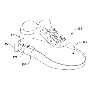
112.
[00112] Therefor, the middle part 84 together with the top part 82 provide for
upwardly supporting the foot at section 116 all the while leaving a portion of
the top
part 84 such as portion 38 in Figure 13 without any material thereunder (like
channel
22 in Figure 13) so that there is no tension under portion P of the foot F
which
corresponds to the position of the plantar fascia 3 (see Figures 2 and 9).
[00113] The inner sole structure 78 can be integrated to the footwear 80 or
auxiliary
thereto for being mounted to the footwear 80 by assembling the parts thereof
as
shown herein.
[00114] With reference to Figure 12, there is shown an inner sole structure
120
comprising a bottom sole portion 122 that is molded within footwear including
a
channel 124 so positioned as to be aligned with the part P of the sole S of
the foot
corresponding to the plantar fascia. In this example, the channel 124 is
concave
cylindrical like groove dug into the top surface 126 of the bottom sole
portion 122.
The channel 124 is covered by a top part such as an insole as previously
described.
The channel 124 is defined by side curved walls 128A and 128B which meet at a
curved bottom floor 130. The channel 132 has front end 132 which can be open
and a closed rear end 134. The channel 132 may be tapered with the front
portion
thereof having a smaller width than the rear portion thereof as shown in
Figure 12.
Thus, providing a configuration that generally corresponds to channel 22 in
Figure
9. In a embodiment, circular ridges 136 extend along the side walls 128A and
128B
via the bottom floor 130 therebetween providing semi-ring or rib like
structures which
provide stability to the material forming the concave cylindrical groove 124.
In an
embodiment, the concave groove 124 is molded in the shape of the fascia which
is
round thereby accommodating this shape.
Date Recue/Date Received 2023-08-25
28
[00115] It should be noted that for all inner sole structures provided herein,
the
portion 38 in Figure 13 of the top part which lies above the channel 22 may
bend
inwardly as indicated by 38' thereby providing no tension at all to the
portion P of
the sole S of the foot. The portion P only feels material 38 but this material
is loose
and free moving along with the skin without any counter force.
[00116] The undersurface of any of the inner sole structures provided herein
that
engages the structural inner surface of footwear may be provided with adhesive
material for adhesively connecting thereto.
[00117] In an embodiment, the channels of the inner sole structures herein
accommodate the shape of the fascia and provide for releasing the tension of
the
fascia as the user walks or runs.
[00118] In an embodiment, the inner sole structures herein can be integrated
in a
moldable material in an insole or footwear.
[00119] In an embodiment, the inner sole structures herein can be integrated
within
footwear by layering one or more layers of material to create the channel.
[00120] In an embodiment, the inner sole structure of at least the part
thereof
defining the channel can be made for example and without limitation thereto
from
rubber, epoxy polymer, carbon fibers, liege, Vibram and other moldable types
of
convenient material and combinations thereof.
[00121] The plantar fascia is a thick band of connective tissue that runs
along the
underside of the foot, from the heel bone to the metatarsals. Its function is
to support
the arch of the foot by carrying tension when the foot bears weight. By
providing an
empty channel right under the plantar fascia, this creates a soft spot within
the insole
that relaxes the plantar fascia and thus avoids pain to the wearer and injury.
Date Recue/Date Received 2023-08-25
29
[00122] Generally stated and in accordance with an aspect of the present
disclosure, there is provided an inner sole structure for being mounted to
footwear.
The footwear comprises a footwear sole defining an outsole for engaging the
ground
and an inner sole part for supporting a foot of a footwear user. The inner
sole
structure comprises a support element for being mounted to the inner sole part
of
the footwear to be engaged by the foot. When the support member is mounted to
the inner sole part of the footwear it is positioned to be engaged by a region
of the
foot corresponding to a position extending between at least near a fifth
metatarsal
rear end position of the foot to a heel bone position of the foot for
providing stability
to the foot for controlled supination.
[00123] With reference to Figures 9, and 14-18, non-restrictive illustrative
embodiments will be described to further exemplify the disclosure only and by
no
means limit the scope thereof.
[00124] With reference to Figures 14 and 15, there is shown an auxiliary inner
sole
structure 150 for being positioned within footwear, such as shoe 152 to overly
the
top surface 154 of the footwear inner sole part 156 of the sole 158.
[00125] The inner sole structure 150 comprises a main sole body 160 defining a
top surface 162, an undersurface 164 and a perimeter 166 therebetween. The
perimeter 166 defines the front and rear ends, 168 and 170, respectively of
the body
160 as well as the lateral sides 172A and 172B of the body 160.
[00126] A support element in the form of a bar 174 is positioned on the
undersurface 164 of body 160 towards the lateral side 172A and at least near
the
rear end 170. The inner sole structure 150 is positioned on the top sole
surface 154
of the footwear 152 with the support rested thereon as well and keeping a
portion
176 of the undersurface 164 spaced from the footwear to sole surface 154. When
Date Recue/Date Received 2023-08-25
30
the foot F engages the inner sole structure 150 the support bar 174 is pushed
into
the sole 158 which is resilient and thereby causes an opposite upward
resistance
to the support bar 174 pushing into the region of the foot F that overlies the
support
bar 174.
[00127] Turning to Figure 18, the support element 174 is so positioned as to
engagingly interface with the side region R of the foot F corresponding to the
area
from about or near (including just behind) the end 39" of the fifth metatarsal
39 to
about or near the beginning 27' of the heel bone (calcaneus 27).
[00128] In an embodiment shown in Figure 9, the support element 174 is
positioned to engagingly interface with the region R of the sole S of foot F
corresponding to the area right behind the fifth metatarsal 39 which ends at
39" and
runs along until a front portion of the heel bone (calcaneus 27).
[00129] As previously discussed, a golf swing, the outside of each ankle
constantly
gets turned over into the ground i.e. supinates which leads to swaying. Thus,
the
support element 174 stabilises the fifth metatarsal to provide stability to
the ankle
preventing supinations and thus avoiding the swaying.
[00130] Turning back to Figure 7, when the right foot F-R in over supination,
the
support element 168 would be positioned in region R' which would interface
with
region R thus stabilizing the the foot F-R from over supination. This position
of the
support element 168 is better shown in region R' on the left foot F-L of
Figure 7
which engagingly interfaces with the region R of the foot F-L.
[00131] In an embodiment, the support element 174 comprises a rectangular bar.
In an embodiment the support element 174 has a length from about 8mm to about
18mm. In an embodiment, the support element 174 is made of rigid material. In
an
embodiment, the support element is made of high-density material. In
an
Date Recue/Date Received 2023-08-25
31
embodiment, the support element 174 has a width of about 10 mm to about 20 mm.
In an embodiment, the support element 174 has a length of about 20 to about 40
mm.
[00132] With reference to Figures 16, 17A and 17B, there is shown an inner
sole
structure 180 that is integrated into the footwear 182. The inner sole
structure 180
comprises a top part or insole 184 overlying a bottom part 186 which is the
inner
part of the sole 188 defining the outer sole 190. The inner sole structure
comprises
the support element 174 integrated within the inner part 186 of the sole 188.
Figure
17A shows the position of the inner sole structure 180 when not use and Figure
17B
shows the position of the inner sole structure 180 when engaged by a foot F.
The
weight pushes the insole 184 inwardly into the inner sole part 186 with the
support
member 174 pushing upwardly against the sole S of the foot F at region R
thereof
which is the region corresponding to the anatomical area right behind the
fifth
metatarsal 39.
[00133] In an embodiment, the inner sole structure comprises the support
element
174herein positioned in the inner sole part of footwear.
[00134] The support element 174 provides for stabilizing the fifth metatarsal
and
extends to the front of the heel. The foregoing arrangement provides for
controlling
supinations or inversion of the foot and ankle thus preventing swaying.
The
foregoing arrangement provides for controlling subtalar and midtarsal joint
motion
which is required to stabilize the lateral ankle ligaments.
[00135] The various features described herein can be combined in a variety of
ways within the context of the present disclosure so as to provide still other
embodiments. Indeed, the support element 174 can be included into the inner
sole
structures 10, 10', 10" and 78 and 120. As such, the embodiments are not
mutually
Date Recue/Date Received 2023-08-25
32
exclusive. Moreover, the embodiments discussed herein need not include all of
the
features and elements illustrated and/or described and thus partial
combinations of
features can also be contemplated. Furthermore, embodiments with less features
than those described can also be contemplated.
[00136] It is to be understood that the present disclosure is not limited in
its
application to the details of construction and parts illustrated in the
accompanying
drawings and described hereinabove. The disclosure is capable of other
embodiments and of being practiced in various ways. It is also to be
understood
that the phraseology or terminology used herein is for the purpose of
description
and not limitation. Hence, although the present disclosure has been provided
hereinabove by way of non-restrictive illustrative embodiments thereof, it can
be
modified, without departing from the scope, spirit and nature thereof and of
the
appended claims.
Date Recue/Date Received 2023-08-25