Note: Descriptions are shown in the official language in which they were submitted.
CA 03210700 2023-08-04
Attorney Ref. No.: 1153P029CA01 1
Energy-saving arrangement for twin-screw ships
TECHNICAL FIELD
The invention relates to an arrangement for reducing the propulsion-power
requirement of a twin-screw ship, comprising a first propeller and a second
propeller
and comprising a first guiding device and a second guiding device, wherein,
viewed in
the forward direction of travel of the watercraft, the first guiding device is
arranged in
front of the first propeller, and the second guiding device is arranged in
front of the
second propeller. Furthermore, the invention relates to a watercraft, in
particular a
twin-screw ship, comprising such an arrangement.
BACKGROUND
Different devices for reducing the propulsion-power requirement of a
watercraft are
already known. For example, a ring nozzle upstream of the propeller in the
direction of
travel of the watercraft can optimize an inflow of the propeller, thereby
having a
positive effect on the energy consumption of the watercraft.
Furthermore, active devices are known to reduce friction losses or swirl
losses between
the water and the hull. Such devices can create air bubbles via nozzles, which
are
distributed along the hull and reduce the friction of the hull, allowing
additional energy
savings.
In ships with asymmetrical skegs or sterns, such as twin-screw ships for
example, the
asymmetry of the skeg already generates a pre-swirl of an inflow of the
propellers in
some areas. However, the pre-swirl is not evenly formed in front of the
propeller, which
is arranged in the flow direction behind the skeg, which means that inflow can
take
place that is not optimal for the propeller. However, the already known
solutions for
reducing the drive power requirement cannot be used for a targeted
optimization of
the pre-swirl.
Date Recue/Date Received 2023-08-04
CA 03210700 2023-08-04
Attorney Ref. No.: 1153P029CA01 2
SUMMARY
The aim of the invention is to create an improved arrangement for reducing the
propulsion-power requirement or for reducing the power consumption of twin-
screw
ships.
This problem is solved by the features indicated in Claim 1 and Claim 12.
Further
favourable embodiments of the invention are described in the dependent claims.
In accordance with one aspect of the invention, an arrangement is provided to
reduce
the propulsion-power requirement of a twin-screw vessel.
The arrangement comprises a first propeller and a second propeller.
Furthermore, the
arrangement comprises a first guiding device and a second guiding device,
wherein,
when viewed in the forward direction of travel of the watercraft, the first
guiding device
is arranged in front of the first propeller, and the second guiding device is
arranged in
front of the second propeller.
The first propeller and the second propeller are attached to a first propeller
shaft and
to a second propeller shaft, wherein the first propeller shaft defines a first
propeller
axis, and the second propeller shaft defines a second propeller axis.
According to the invention, the first guiding device and the second guiding
device each
comprise at least one fin, which extends from the propeller axes, wherein the
fin of the
first guiding device and of the second guiding device extends outwardly
towards the
sides of the watercraft.
In particular, at least one fin of the first guiding device and of the second
guiding device
is arranged in an area with reduced pre-swirl.
Furthermore, at least one fin can extend radially or substantially radially
from the
propeller axes, for example.
The fin of the first guiding device extends towards a first side of the
watercraft, while
the fin of the second guiding device extends towards a second side of the
watercraft,
Date Recue/Date Received 2023-08-04
CA 03210700 2023-08-04
Attorney Ref. No.: 1153P029CA01 3
in particular, towards a side opposite to the first side of the watercraft. In
particular,
the fin of the first guiding device can extend towards the starboard side and
the fin of
the second guiding device can extend towards the port side, wherein no fins of
the two
guiding devices extend inwardly, i.e., into an area between the propellers.
Therefore,
no fins are provided in the inner area between the propellers.
It is provided to arrange the guiding devices on the outside, particularly on
the lateral
skegs, when the directions of rotation of the propellers are directed
inwardly. As a
result, the guiding devices of the arrangement are arranged on the impinging
sides of
the propellers, at which there is a reduced or non-existent pre-swirl.
In the remaining areas of the inflow of the propellers, the asymmetry of the
skegs
around the propellers already generates a pre-swirl. The two guiding devices
can
therefore only be arranged in areas of the inflow where there is no pre-swirl.
By using
the guiding devices, and section-by-section pre-swirl can be generated during
inflow of
the propellers This results in an inflow of the propellers, which is
essentially completely
impinged by a pre-swirl.
The targeted or area-by-area generation of the pre-swirl in areas of the water
masses
flowing to the propellers reduces flow losses. There is an interaction between
the water
flow and the guiding devices in designated areas, which are determined by the
shape
of the skegs.
Such areas, which require the use of guiding devices, can be determined with
the help
of a flow simulation in the direction of travel of the watercraft in front of
the propellers.
In particular, such a flow simulation can be a CFD (Computational Fluid
Dynamics) flow
simulation.
Preferably, the first guiding device and the second guiding device each
comprise at least
two fins.
In an favourable embodiment, the at least two fins of the first guiding device
and of the
second guiding device are at an angle to each other, wherein the at least two
fins of the
guiding devices are attached in the area of shaft bearings, in particular,
towards the
outer shell of the stern tubes, which are designed to support the first and
second
Date Recue/Date Received 2023-08-04
CA 03210700 2023-08-04
Attorney Ref. No.: 1153P029CA01 4
propeller shafts of the watercraft, or towards a watercraft hull in the area
of stern-
posts. The angle between the two fins of the respective guiding device can be
defined
as the rotational axis of the fins starting from the shaft bearing.
The angle between two fins or a plurality of angles between at least three
fins of the
guiding device can be selected in such a way that the fins span an area with
reduced
pre-swirl and thus optimally apply a pre-swirl to the corresponding water flow
before
said water flow hits a propeller.
The angles between the at least three fins can be selected to be identical or
different,
such that a defined pre-swirl distribution can be generated for the inflow of
the
propellers. The pre-swirl distribution can generate a pre-swirl that varies
along a cross-
sectional area of the water masses flowing into the propellers.
According to a further embodiment, at least one fin of the guiding devices is
designed
to generate a pre-swirl during an inflow of the first and second propellers,
wherein the
pre-swirl is generated by the respective guiding device in an inflow area of
the propeller
which has no, or a reduced pre-swirl generated by at least one asymmetrical
skeg or
stern. This measure results in a uniform or more uniform inflow of the
propellers along
the entire cross-sectional area as inflow occurs.
The targeted influence of the water masses by the guiding devices minimizes
swirl
losses and thus results in a saving in the power requirements of the
watercraft.
The inflow of the propellers can be precisely adjusted if the fin has a length
that
corresponds to 65% to 110% a propeller radius of the propellers, preferably
80% to
110%, being particularly preferred, 90% to 105%, and being mostly preferred,
100%
thereof. In particular, this can reduce the resistance introduced by the
guiding devices
in addition to the ship's hull.
If at least two fins per guiding device are provided, the fins of the guiding
devices can
be structurally reinforced, in particular, if the at least two fins of the
first and of the
second guiding devices are connected by a connecting bar.
Date Recue/Date Received 2023-08-04
CA 03210700 2023-08-04
Attorney Ref. No.: 1153P029CA01 5
In addition, the at least one connecting bar, which can run, for example, in
the form of
a ring segment or a straight connection between the at least two fins, can
additionally
influence the flow of the propellers. This can be achieved by profiling and/or
distortion
or twisting the connecting bar.
The connecting bar can support the fins particularly efficiently if it is
preferably
between 30% and 70% of the length of the fins when viewed along a length of
the fins,
being particularly preferred, between 45% and 55% of the length of the fins or
centrally
arranged. A single connecting bar can couple or connect a plurality of fins,
such as three
or more fins for example.
In addition, or as an alternative, the connecting bar can connect the tips of
two fins
together or mechanically connect a tip of a first fin to a second fin.
Alternatively, a plurality of connecting bars can be provided, which are
respectively
positioned between two fins. A plurality of connecting bars can form a row,
which
mechanically couple or connect all fins of a guiding device with each other.
Preferably, at least one connecting bar can create a statically fixed or rigid
connection
between at least two fins.
In accordance with another exemplary embodiment, the connecting bar has
straight or
curved shape along a length and/or width of the connecting bar. At least one
connecting bar can comprise an bearing-surface profile through which the
inflow or
water flow can be specifically influenced.
Alternatively, the at least one connecting bar can have a profile to minimize
its drag
with respect to the inflow of the propellers.
The arrangement and the guiding devices can be technically particularly simple
if each
of the guiding devices comprises exactly two fins.
Alternatively, each of the guiding devices can comprise exactly three fins.
Alternatively, each of the guiding devices can comprise exactly one fin.
Date Recue/Date Received 2023-08-04
CA 03210700 2023-08-04
Attorney Ref. No.: 1153P029CA01 6
According to a further embodiment, the propellers are designed as counter-
rotating
propellers, wherein the first guiding device is arranged on an impinging side
of the first
propeller, and the second guiding device is arranged on an impinging side of
the second
propeller. Due to an asymmetrical shape of the skegs, areas of the inflow or
the
incoming water with a reduced pre-swirl are formed on the impinging sides of
the
propellers, which can be amplified by the guiding devices.
In particular, the two propellers are designed to rotate inwardly at the top,
i.e., in the
direction of an area between the propellers of the watercraft when the fins of
the two
guiding devices project outwardly towards the sides of the watercraft.
The terms "turning inwardly" and "turning outwardly" respectively refer to the
direction of rotation of the propeller when considering a point in the upper
part of the
propeller (i.e., a 12 o'clock position) in relation to the state of the
propeller installed
onto the watercraft. When the propeller rotates outwardly, the movement of the
propeller at the upper point of rotation is therefore directed outwardly
towards the
outside of the watercraft. If the propeller rotates inwardly, the movement of
the
propeller at the upper point of rotation is directed inwardly in the direction
of an area
between the two propellers.
The guiding devices can be positioned particularly efficiently on the
watercraft if they
are positioned essentially mirror-symmetrical with respect to each other with
respect
to a vertical plane of symmetry of the watercraft. As a result, the straight-
line stability
of the watercraft can remain unimpaired by the guiding devices.
The inflow of the propellers through the water can be controlled particularly
precisely
with the help of the guiding devices and the corresponding fins if the fins
have a
constant or changing profiling and/or position along their length.
In accordance with another aspect of the invention, a watercraft, in
particular, a twin-
screw ship, is provided. The watercraft has an arrangement according to the
invention
with a first guiding device and a second guiding device. The two guiding
devices are
preferably attached to the shaft bearings of the propeller axes and extend in
the
direction of the sides of the watercraft. In particular, the first guiding
device can extend
Date Recue/Date Received 2023-08-04
CA 03210700 2023-08-04
Attorney Ref. No.: 1153P029CA01 7
to a first or right side of the watercraft, and the second guiding device can
extend to a
second or left side of the watercraft.
BRIEF DESCRIPTION OF THE DRAWINGS
A plurality of exemplary embodiments of the invention are explained in more
detail
below on the basis of the drawings. The figures show:
Fig. 1 an exemplary simulation of the pre-swirl around propellers of a
twin-screw
ship,
Fig. 2a a perspective illustration of an arrangement according to the
invention in
accordance with a first embodiment,
Fig. 2b perspective illustrations of an arrangement according to the invention
in
accordance with a second embodiment,
Fig. 3 rear view of the arrangement according to the invention in
accordance with
the second embodiment.
DETAILED DESCRIPTION
Figure 1 shows an exemplary simulation of the pre-swirl in the area of
propellers 20, 21
of a twin-screw ship 100, which are shown as an example in Fig. 2a and Fig. 3.
The
simulation shows a cross-sectional area of an inflow or in the direction of
propellers 20,
21 of flowing water with a corresponding pre-swirl distribution. A pre-swirl
around a
first propeller axis 22 and around a second propeller axis 23 of a watercraft
100
designed as a twin-screw ship is shown.
An asymmetrical shape of a skeg 110 of the watercraft 100 creates areas with
an
increased pre-swirl 120 and areas with a reduced or non-existent pre-swirl
130. The
corresponding arrow lengths illustrate an exemplary measure of pre-swirl,
wherein
light-shaded areas correspond to reduced pre-swirl and dark-shaded areas
correspond
to increased pre-swirl with respect to a propeller rotation direction.
The arrangement shown in Fig. 2a according to the invention 10 comprises
guiding
devices 30, 31, which are only arranged in areas 130 in which there is no pre-
swirl or an
unfavourable inflow.
Date Recue/Date Received 2023-08-04
CA 03210700 2023-08-04
Attorney Ref. No.: 1153P029CA01 8
Figure 2a shows a perspective illustration of an arrangement according to the
invention
in accordance with a first embodiment. Arrangement 10 serves to reduce the
propulsion-power requirement of the twin-screw ship or watercraft 100. For the
sake
5 of clarity, only a second or left side of a stern section of watercraft
100 is shown. In Fig.
3, a stern view of watercraft 100 is shown, which illustrates both sides. Fig.
2a is
described with reference to Fig. 3.
Arrangement 10 comprises a first propeller 20 and a second propeller 21.
Furthermore,
10 the arrangement 10 comprises a first guiding device 30 and a second
guiding device 31.
When viewed in the forward direction F of the watercraft 100, the first
guiding device
30 is arranged in front of the first propeller 20, and the second guiding
device 31 is
arranged in front of the second propeller 21.
The first propeller 20 and the second propeller 21 are attached to a first
propeller shaft
(not shown) and to a second propeller shaft (not shown), wherein the first
propeller
shaft defines the first propeller axis 22 and the second propeller shaft
defines the
second propeller axis 23.
In the illustrated exemplary embodiment, the first guiding device 30 and the
second
guiding device 31 each comprise two fins 32, 33, which extend radially from
the
propeller axes 22, 23. The fins 32, 33 of the first guiding device 30 and of
the second
guiding device 31 extend outwardly towards the sides of the watercraft 101,
102.
In particular, the first guiding device 30 extends to a first or right side of
the watercraft
101, and the second guiding device 31 extends to a second or left side of the
watercraft
102, respectively.
The two fins 32, 33 of the first and second guiding devices 30, 31 are at an
angle A to
each another. The two fins 32, 33 of the guiding devices 30, 31 are attached
by way of
example in the area of shaft bearings 40, in particular, to shells of stern
tubes which are
designed to support the first and second propeller shafts of the watercraft
100.
Date Recue/Date Received 2023-08-04
CA 03210700 2023-08-04
Attorney Ref. No.: 1153P029CA01 9
In Fig. 2b, a perspective illustration of an arrangement according to the
invention 10 in
accordance with a second embodiment is shown. In particular, in Fig. 2b a side
view of
the watercraft 100 is shown analogous to Fig. 2a. In contrast to the
embodiment that
has already been described, the arrangement 10 comprises a connecting bar 50
radially
centred between the fins 32, 33.
The fins 32, 33 have a length L, which corresponds to 100% of a propeller
radius of the
propellers 20, 21.
The two radially protruding fins 32, 33 comprise a connecting bar 50 arranged
approximately radially in the centre. The connecting bar 50 can structurally
reinforce
the fins 32, 33. In particular, the fins 32, 33 are mechanically connected to
each other
by the connecting bar 50.
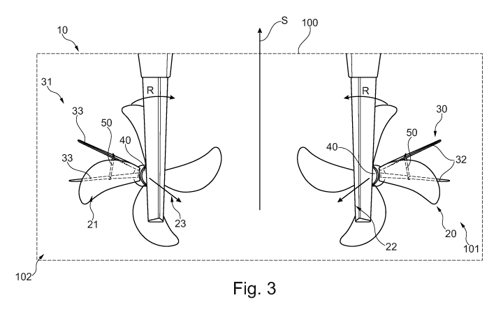
In Fig.3, a stern view of watercraft 100. is shown. Thereby, the entire
arrangement 10
is illustrated. The first and second guiding devices 30, 31 extend in the
direction of the
first and second sides of the watercraft respectively, 101, 102 starting from
the shells
of the stern tubes and shaft bearings 40, respectively. The direction of
rotation of the
two propellers is indicated by the two arrows R, which are arranged inwardly
at an
upper point of rotation, i.e., at a 12:00 o'clock position.
In the case of propellers 20, 21 rotating inwardly in the direction of arrows
R, the two
guiding devices 30, 31 are arranged on the outside or on the impinging sides
of
propellers 20, 21. Based on a view from the rear, the guiding devices 30, 31
are
therefore located at 3:00 a.m. and at 9:00 a.m. In such a formation of
arrangement 10,
the guiding devices 30, 31 are preferably symmetrically arranged with respect
to each
other with respect to a vertical plane of symmetry S of the watercraft 100.
Such an arrangement of the guiding devices 30, 31 can be used to achieve
particularly
high energy savings or fuel reduction, particularly in the case of twin-screw
ships.
Preferably, in addition to the guiding devices 30, 31, no other energy-saving
devices
comprising fins or nozzles on the watercraft are arranged in the area of
propellers 20,
21 or even on rudders.
Date Recue/Date Received 2023-08-04
CA 03210700 2023-08-04
Attorney Ref. No.: 1153P029CA01 10
Figure 3 also illustrates the symmetrical structure of arrangement 10 and
guiding
devices 30, 31. It can also be seen that the connecting piece or the
connecting bar 50 is
attached approximately in the middle of the fins 32, 33 when viewed along the
length
L of the fins 32, 33.
10
Date Recue/Date Received 2023-08-04
CA 03210700 2023-08-04
Attorney Ref. No.: 1153P029CA01 11
Reference list
100 watercraft / twin-screw ship
101 first / right side of the watercraft
102 second / left side of the watercraft
110 skegs of the watercraft
120 areas with an increased pre-swirl
130 areas with a reduced pre-swirl
10 arrangement
first propeller
21 second propeller
22 first propeller axis
15 23 second propeller axis
first guiding device
31 second guiding device
32 fins of the first guiding device
20 33 fins of the second guiding device
shaft bearing
connecting bar
A angle between two fins
F forward direction of travel
L length of a fin
S vertical plane of symmetry of the watercraft
R direction of rotation
Date Recue/Date Received 2023-08-04