Note: Descriptions are shown in the official language in which they were submitted.
CA 03211217 2023-08-16
WO 2022/178141
PCT/US2022/016815
NANO-BUBBLE GENERATOR
CLAIM OF PRIORITY
This application claims priority to U.S. Provisional Application Ser. No.
63/150,973,
filed on Feb. 18, 2021, the entire contents of which are hereby incorporated
by reference.
TECHNICAL FIELD
This invention relates to generating nano-bubbles in a liquid carrier.
BACKGROUND
Nano-bubbles are stable in liquid carriers for extended periods of time,
allowing them
to be transported without coalescing in the liquid carrier. These properties
make nano-
bubbles useful in a variety of fields, including water treatment, plant
growth, aquaculture, and
sterilization.
SUMMARY
In a first aspect, an apparatus for generating a composition that includes
nano-bubbles
in a liquid carrier is described. The apparatus includes: (a) an elongate
housing that includes a
first end and a second end, and defines a liquid inlet, a liquid outlet, and
an interior cavity
adapted for receiving the liquid carrier from a liquid source; (b) a gas-
permeable member at
least partially disposed within the interior cavity of the housing that
includes a first end
adapted for receiving a pressurized gas from a gas source, a second end, and a
porous
sidewall extending between the first and second ends, the gas-permeable member
defining an
inner surface, an outer surface, and a lumen; and (c) at least one electrical
conductor adapted
to generate a magnetic flux parallel to the outer surface of the gas-permeable
member as the
liquid carrier flows from the liquid inlet to the liquid outlet. The housing
and gas-permeable
member are configured such that the flow rate of the liquid carrier from the
liquid source as it
flows parallel to the outer surface of the gas-permeable member from the
liquid inlet to the
liquid outlet is greater than the turbulent threshold of the liquid to create
turbulent flow
conditions, thereby allowing the liquid to shear gas from the outer surface of
the gas-
permeable member and form nano-bubbles in the liquid carrier.
In some embodiments, the gas-permeable member is electrically conductive. The
electrical conductor may be an electromagnetic coil (e.g., a stator) or a
wire. In some cases,
1
CA 03211217 2023-08-16
WO 2022/178141
PCT/US2022/016815
the apparatus includes a pair of electrical conductors, one of which is the
gas-permeable
member and the other of which is, e.g., an electromagnetic coil or a wire.
In some embodiments, the apparatus includes a helicoidal member adapted to
cause
the liquid carrier to rotate as it flows from the liquid inlet to the liquid
outlet. The helicoidal
member may be in the form of a pattern integral to the gas-permeable member,
the housing,
or both. In other embodiments, the helicoidal member includes an
electromagnetic coil
adapted to generate a magnetic flux parallel to the outer surface of the gas-
permeable member
as the liquid carrier flows from the liquid inlet to the liquid outlet. In the
latter case, the
helicoidal member also performs the role of the electrically conductive
member.
The electrical conductor may be located on the exterior of the housing, in the
interior
cavity of the housing, or on the outer surface of the gas-permeable member.
The electrical
conductor may also be located downstream or upstream of the gas-permeable
member.
The apparatus may further include a hydrofoil located in the interior cavity
of the
housing. The hydrofoil may be located upstream or downstream of the gas-
permeable
member. In some embodiments, the hydrofoil is physically attached to the gas-
permeable
member. The hydrofoil causes the liquid carrier to rotate as it flows past the
hydrofoil.
In a second aspect, a second apparatus for producing a composition that
includes
nano-bubbles dispersed in a liquid carrier is described. The apparatus
includes: (a) an
elongate housing that includes a first end and a second end, and defines a
liquid inlet, a liquid
outlet, and an interior cavity adapted for receiving the liquid carrier from a
liquid source; (b)
a gas-permeable member at least partially disposed within the interior cavity
of the housing,
the gas-permeable member including a first end adapted for receiving a
pressurized gas from
a gas source, a second end, and a porous sidewall extending between the first
and second
ends, the gas-permeable member defining an inner surface, an outer surface,
and a lumen; (c)
one or more electrodes, one of which is an electromagnetic coil adapted to
generate a
magnetic flux parallel to the outer surface of the gas-permeable member as the
liquid carrier
flows from the liquid inlet to the liquid outlet, (d) a helicoidal member
adapted to cause the
liquid carrier to rotate as it flows from the liquid inlet to the liquid
outlet, and (e) a hydrofoil
located in the interior cavity of the housing. The housing and gas-permeable
member are
configured such that the flow rate of the liquid carrier from the liquid
source as it flows
parallel to the outer surface of the gas-permeable member from the liquid
inlet to the liquid
outlet is greater than the turbulent threshold of the liquid to create
turbulent flow conditions,
thereby allowing the liquid to shear gas from the outer surface of the gas-
permeable member
and form nano-bubbles in the liquid carrier.
2
CA 03211217 2023-08-16
WO 2022/178141
PCT/US2022/016815
In some embodiments, the helicoidal member includes the electromagnetic coil.
In a third aspect, a method for producing a composition including nano-bubbles
dispersed in a liquid carrier using the apparatus described in the first and
second aspects of
the invention is described. The method includes: (a) introducing a liquid
carrier from a
liquid source into the interior cavity of the housing through the liquid inlet
of the housing at a
flow rate that creates turbulent flow above the turbulent threshold at the
outer surface of the
gas-permeable member; (b) applying a magnetic flux parallel to the outer
surface of the gas-
permeable member as the liquid carrier flows from the liquid inlet to the
liquid outlet; and (c)
introducing a pressurized gas from a gas source into the lumen of the gas-
permeable member
at a gas pressure selected such that the pressure within the lumen is greater
than the pressure
in the interior cavity of the housing, thereby forcing gas through the porous
sidewall and
forming nano-bubbles on the outer surface of the gas-permeable member. The
liquid carrier
flowing parallel to the outer surface of the gas-permeable member from the
liquid inlet to the
liquid outlet removes nano-bubbles from the outer surface of the gas-permeable
member to
form a composition comprising the liquid carrier and the nano-bubbles
dispersed therein.
In some embodiments, the flow rate is at least 2 m/s. The method may include
applying an oscillating magnetic flux, e.g., a high frequency oscillating
magnetic flux.
In a fourth aspect, a third apparatus for producing a composition including
nano-
bubbles dispersed in a liquid carrier is described. The apparatus includes:
(a) an elongate
housing including a first end and a second end, the housing further including
an interior
cavity and a gas inlet adapted for introducing pressurized gas from a gas
source into the
interior cavity; (b) a gas-permeable member at least partially disposed within
the interior
cavity of the housing, the gas-permeable member including a liquid inlet
adapted for
receiving a liquid from a liquid source, a liquid outlet, and a porous
sidewall extending
between the liquid inlet and liquid outlet, and defining an inner surface, an
outer surface, and
a lumen through which liquid flows; and (c) at least one electrical conductor
adapted to
generate a magnetic flux parallel to the inner surface of the gas-permeable
member as the
liquid carrier flows from the liquid inlet to the liquid outlet. The housing
and gas-permeable
member are configured such that the flow rate of the liquid carrier from the
liquid source as it
flows parallel to the inner surface of the gas-permeable member from the
liquid inlet to the
liquid outlet is greater than the turbulent threshold of the liquid to create
turbulent flow
conditions, thereby allowing the liquid to shear gas from the inner surface of
the gas-
permeable member and form nano-bubbles in the liquid carrier.
3
CA 03211217 2023-08-16
WO 2022/178141
PCT/US2022/016815
In a fifth aspect, a method for producing a composition including nano-bubbles
dispersed in a liquid carrier using the apparatus described in the fourth
aspect of the invention
is described. The method includes: (a) introducing a liquid carrier from a
liquid source into
the interior cavity of the gas-permeable member through the liquid inlet of
the housing at a
flow rate that creates turbulent flow above the turbulent threshold at the
outer surface of the
gas-permeable member; (b) applying a magnetic flux parallel to the inner
surface of the gas-
permeable member as the liquid carrier flows from the liquid inlet to the
liquid outlet; and (c)
introducing a pressurized gas from a gas source into the interior cavity of
the housing at a gas
pressure selected such that the pressure within the interior cavity of the
housing is greater
than the pressure in the interior of the gas-permeable member, thereby forcing
gas through
the porous sidewall and forming nano-bubbles on the inner surface of the gas-
permeable
member. The liquid carrier flowing parallel to the inner surface of the gas-
permeable
member from the liquid inlet to the liquid outlet removes nano-bubbles from
the inner surface
of the gas-permeable member to form a composition comprising the liquid
carrier and the
nano-bubbles dispersed therein.
In some embodiments, the flow rate is at least 2 m/s. The method may include
applying an oscillating magnetic flux, e.g., a high frequency oscillating
magnetic flux.
In each of the above-described apparatuses and methods, configuring the
apparatus
such that the flow rate of the liquid carrier from the liquid source as it
flows parallel to the
inner or outer surface of the gas-permeable member from the liquid inlet to
the liquid outlet is
greater than the turbulent threshold of the liquid to create turbulent flow
conditions
minimizes nano-bubble coalescence. Including at least one electrical conductor
to generate a
magnetic flux (e.g., a high frequency oscillating magnetic flux) parallel to
the inner or outer
surface of the gas-permeable member as the liquid carrier flows from the
liquid inlet to the
liquid outlet increases both nano-bubble production and nano-bubble production
rate.
Measuring the change in resistance of the electrical conductor can be used to
detect the
presence of nanobubbles in the fluid.
The helicoidal member further increases nano-bubble production and nano-bubble
production rate by imparting angular velocity to the liquid carrier to cause
swirling, thereby
enhancing the efficiency of capturing nano-bubbles at the interface between
gas-permeable
member and liquid stream. The hydrofoil further increases nano-bubble
production and nano-
bubble production rate by creating high turbulence regions in the fluid
flowing through the
apparatus based on the surface of the hydrofoil and the turbulent trailing
edge downstream of
the hydrofoil.
4
CA 03211217 2023-08-16
WO 2022/178141
PCT/US2022/016815
The apparatuses and methods described above can be used in a variety of
applications.
Examples include water treatment, e.g., wastewater treatment to oxygenate
and/or remove
contaminant in a body of water. Other examples include aquaculture and plant
growth, where
the composition can be used to deliver oxygen or other nutrients. Yet another
example is
cleaning and sterilization, e.g., in hot tubs or spas to minimize or eliminate
the use of
chemicals such as chlorine.
The details of one or more embodiments of the invention are set forth in the
accompanying drawings and the description below. Other features, objects, and
advantages of
the invention will be apparent from the description and drawings, and from the
claims.
DESCRIPTION OF DRAWINGS
FIG. 1A is a top view of an example apparatus for producing a composition
comprising nano-bubbles dispersed in a liquid carrier.
FIG. 1B is a cross-sectional side view of the apparatus of FIG. 1A.
FIG. 1C is an exploded view of the apparatus of FIG. 1A.
FIG. 2A is a top view of an example apparatus for producing a composition
comprising nano-bubbles dispersed in a liquid carrier.
FIG. 2B is a cross-sectional side view of the apparatus of FIG. 2A.
FIG. 3A is a top view of an example apparatus for producing a composition
comprising nano-bubbles dispersed in a liquid carrier.
FIG. 3B is a cross-sectional side view of the apparatus of FIG. 3A.
FIG. 4A is a top view of an example apparatus for producing a composition
comprising nano-bubbles dispersed in a liquid carrier.
FIG. 4B is a cross-sectional side view of the apparatus of FIG. 4A.
FIG. 5A is a top view of an example apparatus for producing a composition
comprising nano-bubbles dispersed in a liquid carrier.
FIG. 5B is a cross-sectional side view of the apparatus of FIG. 5A.
FIG. 6A is a top view of an example apparatus for producing a composition
comprising nano-bubbles dispersed in a liquid carrier.
FIG. 6B is a cross-sectional side view of the apparatus of FIG. 6A.
FIG. 7 is a top view of an example apparatus for producing a composition
comprising
nano-bubbles dispersed in a liquid carrier.
FIG. 8 is a top view of an example apparatus for producing a composition
comprising
nano-bubbles dispersed in a liquid carrier.
5
CA 03211217 2023-08-16
WO 2022/178141
PCT/US2022/016815
FIG. 9A is a perspective view of an example hydrofoil.
FIG. 9B is a side view of the hydrofoil of FIG. 9A.
FIG. 9C is a top view of the hydrofoil of FIG. 9A.
FIG. 10A is a top view of an example mount coupled to the hydrofoil of FIG.
9A.
FIG. 10B is a cross-section of the mount of FIG. 10A that excludes the
hydrofoil for
illustrative purposes.
FIG. 10C is a cross-section of the mount of FIG. 10A coupled to the hydrofoil
of FIG.
9A.
FIG. 11 is a schematic diagram of an example permeable member.
FIG. 12 is a schematic diagram of an example apparatus.
Like reference symbols in the various drawings indicate like elements.
DETAILED DESCRIPTION
This disclosure describes an apparatus for producing nano-bubbles in a liquid
carrier.
The nano-bubbles have diameters less than one micrometer (?m). In some
embodiments, the
nano-bubbles have diameters less than or equal to 500 nanometers (nm). In some
embodiments, the nano-bubbles have diameters less than or equal to 200
nanometers (nm).
The apparatuses and methods described herein selectively apply a combination
of
super-cavitation, vorticity, and/or a magnetic field (preferably a high
frequency oscillating
magnetic field) in addition to shear to form nano-bubbles in a liquid carrier.
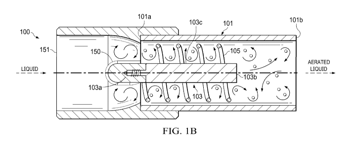
FIGS. 1A and 1B are schematic diagrams showing a top view and a cross-
sectional
side view, respectively, of an exemplary apparatus 100. FIG. 1C is a schematic
diagram
showing an exploded view of the apparatus 100 in which the components of the
apparatus
100 are shown separated from each other. The apparatus 100 includes a housing
101, a
permeable member 103, and an electrical conductor 105. The elongate housing
101 is defined
by a first end 101a, a second end 101b, and an interior cavity adapted for
receiving a liquid
carrier from a liquid source. The housing 101 includes an inlet and an outlet.
The first end
101a can be the inlet and the second end 101b can be the outlet.
The apparatus 100 includes the gas-permeable member 103 at least partially
disposed
within the interior cavity of the housing 101. The permeable member 103
defines an inner
surface, an outer surface, and a lumen. The permeable member 103 can include a
first end
103a adapted for receiving a pressurized gas from a gas source, a second end
103b, and a
porous sidewall 103c extending between the first and second ends 103a, 103b.
The first end
6
CA 03211217 2023-08-16
WO 2022/178141
PCT/US2022/016815
103a of the permeable member 103 can be an open end and the second end 103b of
the
permeable member 103 can be a closed end.
The housing 101 and permeable member 103 can be arranged such that the flow
rate
of the liquid carrier from the liquid source, as it flows parallel to the
outer surface of the
permeable member 103 from the liquid inlet to the liquid outlet, is greater
than the turbulent
threshold of the liquid to create turbulent flow conditions, thereby allowing
the liquid to shear
gas from the outer surface of the gas-permeable member and form nano-bubbles
in the liquid
carrier.
As shown in FIGS. 1A-C, the apparatus 100 includes an electrical conductor 105
in
the form of a helicoidal member (e.g., a helical electrode) that is located in
the interior cavity
of the housing 101. The electrical conductor 105 is adapted to generate a
magnetic flux
parallel to the outer surface of the permeable member 103 as the liquid
carrier flows from the
liquid inlet to the liquid outlet of the housing 101. Preferably, the
electrical conductor 105 is
adapted to generate a high frequency oscillating magnetic flux.
The electrical conductor 105 can be located on the outer surface of the
permeable
member 103. The electrical conductor 105 can surround at least a portion of
the permeable
member 103. The electrical conductor 105 can also be implemented in other
forms. For
example, in some embodiments, the electrical conductor 105 includes a wire. In
some
embodiments, the electrical conductor 105 includes one or more electrodes. In
some
embodiments, the electrical conductor 105 is in the form of an electromagnetic
coil (e.g., a
stator). In some embodiments, the permeable member 103 can serve as the
electrical
conductor 105.
In some embodiments, the apparatus 100 is connected to a source of liquid that
provides the liquid carrier (for example, water). In some embodiments, the
source of liquid is
a vessel or body of water connected to a pump via a suction line. In some
embodiments, the
pump is a variable speed pump. In some embodiments, the pump is connected to
the
apparatus 100 via a discharge line with a control valve. In some embodiments,
the discharge
line is in fluid communication with the housing 101. For example, the liquid
carrier flows
from the pump, through the control valve, through the discharge line, and to
the first end
101a. The percent opening of the control valve can be adjusted to control the
pressure and
flow rate of the liquid carrier to the apparatus 100.
The apparatus 100 can optionally include a hydrofoil 150 shaped to induce
rotation in
the liquid carrier flowing through the apparatus 100. In some embodiments, the
hydrofoil 150
is shaped (e.g., with tapered and/or curved surfaces) to induce super-
cavitation in the liquid
7
CA 03211217 2023-08-16
WO 2022/178141
PCT/US2022/016815
carrier flowing through the apparatus 100. For example, the hydrofoil 150 can
be shaped to
create high turbulence regions in the fluid flowing through the apparatus 100
based on the
surface of the hydrofoil 150 and the turbulent trailing edge downstream of the
hydrofoil 150.
In this disclosure, the terms "downstream" and "upstream" are in relation to
the overall flow
direction of the liquid carrier, for example, through the apparatus 100. For
example, in FIGS.
1A-B, the overall flow direction of the liquid carrier through the apparatus
100 is from left to
right, so "downstream" correlates to "to the right of' and "upstream"
correlates to "to the left
of."
As shown in FIG. 1B, the hydrofoil 150 can be located in the interior cavity
of the
housing 101. At least a portion of the hydrofoil 150 can be located upstream
of the permeable
member 103. The hydrofoil 150 can be physically attached to the permeable
member 103.
Other implementations of the hydrofoil can also be contemplated. For example,
in some
embodiments, at least a portion of the hydrofoil 150 can be located downstream
of the
permeable member 103. The hydrofoil 150 and one or more other components (such
as a
helicodial member and/or the electrical conductor 105) can cooperatively
induce rotation in
the fluid flowing through the apparatus 100.
In some embodiments, the apparatus 100 optionally includes a mount 151. The
mount
can serve to couple two or more components together in the apparatus. As shown
in FIGS.
1A-B, the permeable member 103 and, optionally, the hydrofoil 150, can be
coupled to the
mount 151. The housing 101 can be coupled to the mount 151, for example, the
first end 101a
of the housing 101 can be coupled to the mount 151. Various means for coupling
components
together can be applied. For example, the first end 101a of the housing 101
can engage with
an inner bore of the mount 151. The mount 151 can provide fluid inlet and/or
outlet ports into
its coupled components. For example, the mount 151 can define a port 151a that
is in fluid
communication with the first end 103a of the permeable member 103. The port
151 can be
used to introduce gas into the permeable member 103.
The apparatus 100 is connected to a source of gas. As discussed above, the
source of
gas can be connected to the port 151a (defined by the mount 151), which is in
fluid
communication with the first end 103a of the permeable member 103. The gas can
flow to the
first end 103a and into the lumen of the permeable member 103. As the gas
flows from the
lumen and through the pores of the permeable member 103, nano-bubbles can be
formed and
sheared from the outer surface of the permeable member 103 by the liquid
carrier flowing
across the outer surface of the permeable member 103 at a flow rate above the
turbulent
threshold of the liquid.
8
CA 03211217 2023-08-16
WO 2022/178141
PCT/US2022/016815
In some embodiments, the liquid carrier containing the nano-bubbles formed by
the
apparatus 100 flows out of the apparatus 100 (for example, out of the second
end 101b) to a
discharge line. In some embodiments, the liquid carrier containing the nano-
bubbles formed
by the apparatus 100 flows out of the apparatus 100 to multiple selectable
discharge lines (for
example, in a vessel or body of water).
FIGS. 2A and 2B are schematic diagrams of an exemplary apparatus 200. Although
apparatus 200 includes one or more of the same features (e.g., permeable
member 103, mount
151) of apparatus 100, there are also several distinctions. For example,
apparatus 200
includes a housing 201 that is segmented. The segments of the housing 201 can
be coupled
by the mount 151. The mount 151 can be located between the first end 201a and
the second
end 201b of the housing 201.
The apparatus 200 of FIGS. 2A-B also includes multiple electrical conductors
205,
207. Electrical conductor 205 is an electromagnetic coil (e.g., a stator)
located on an exterior
of the housing 201 downstream of the permeable member 103. Electrical
conductor 205 is a
helicoidal member 207 (e.g., coil electrode) located in the interior cavity of
the housing 201
upstream from the permeable member 103. The helicoidal member 207 can include
a helical
baffle (or a coiled wire) positioned along an inner circumferential wall of
the housing 201.
The helicoidal member 207 is adapted to cause the liquid carrier to rotate as
it flows through
the apparatus 200 (for example, from the liquid inlet to the liquid outlet).
Similar to the
electrical conductor 105 of apparatus 100, the helicoidal member 207 can also
serve as an
electromagnetic coil adapted to generate a magnetic flux (e.g., a high
frequency oscillating
magnetic field) parallel to the outer surface of the permeable member 103 as
the liquid carrier
flows through the apparatus 200 (for example, from the liquid inlet to the
liquid outlet).
In some embodiments, the helicoidal member 207 can be an integral feature of
the
permeable member 103, the housing 201, or both, that causes the liquid carrier
to rotate. For
example, the helicoidal member 207 can include one or more surface features on
a wall of the
permeable member 103, the housing 201, or both, that causes the liquid carrier
flowing
adjacent to the surface to rotate. The surface features may include cavities
and/or protrusions
on a wall. For example, the helicoidal member 207 can include a helical-shaped
surface
formed along an inner wall of the housing in some embodiments.
The apparatuses provided herein can include various electrical conductor
configurations. In some embodiments, one or more electrical conductors (e.g.,
electrical
conductor 205 or helicoidal member 207) are separate components within the
apparatus 200.
For example, the electrical conductor 205 and the helicoidal member 207 can be
separate
9
CA 03211217 2023-08-16
WO 2022/178141
PCT/US2022/016815
components coupled directly to the housing 201 (as shown in Figures 2A-B), or
spaced apart
from the housing 201 (as shown in Figures 1A-B). For example, the helicoidal
member 207
can be in the form of a helical baffle coupled to and disposed about an outer
surface of the
permeable member 103. In some embodiments, at least a portion of the one or
more
electrodes can be positioned upstream, downstream, or at the same approximate
location of
the permeable member 103.
FIGS. 3A and 3B show another exemplary apparatus 300. While apparatus 300
includes some same features (e.g., permeable member 103) of previously
discussed
apparatuses (e.g., apparatuses 100, 200), this section focuses on the
distinctions present in
apparatus 300. For example, apparatus 300 has multiple electrical conductors
located within
the housing 301, including an electrical stator 305 located upstream of the
permeable member
103 and a helicoidal member 307 that surrounds at least a portion of the
permeable member
103. The helicoidal member 307 can be sized as desired. For example, the
helicoidal member
307 of apparatus 300 is longer than the permeable member 103 such that a
portion of the
helicoidal member 307 extends downstream of the permeable member 103. In some
embodiments, the helicodial member 307 can be longer, shorter, or the same
approximate
length of the permeable member along a longitudinal direction.
FIGS. 4A and 4B show another exemplary apparatus 400. While apparatus 400
includes some same features (e.g., permeable member 103) of previously
discussed
apparatuses (e.g., apparatuses 100, 200, 300), this section focuses on the
distinctions present
in apparatus 400. For example, apparatus 400 includes an electrical conductor
405 in the
form of a helicoidal member (e.g., a helical electrode) located on an exterior
of the housing
401. For example, the electrical conductor 405 can include a coiled wire (or
just a coil) that is
coupled directly to and disposed about around the exterior of the housing 401.
The electrical
conductor 405 of apparatus 400 is located upstream of the permeable member
103. In some
embodiments, at least a portion of the electrical conductor 405 can be located
downstream or
at the same approximate location of the permeable member 103. In some
embodiments, the
electrical conductor can be disposed on the mount 405.
FIGS. 5A and 5B show another exemplary apparatus 500. Apparatus 500 includes
some similar features (e.g., permeable member 103) of previously discussed
apparatuses
(e.g., apparatuses 100, 200, 300, 400), but this section focuses on the
distinctions present in
apparatus 500. Apparatus 500 includes an electrical conductor 505 in the form
of a helicoidal
member (e.g., a helical electrode) located on an exterior of the housing 501
positioned
CA 03211217 2023-08-16
WO 2022/178141
PCT/US2022/016815
generally downstream of the permeable member 103 near an outlet end 501b of
the housing
501.
FIGS. 6A and 6B show another exemplary apparatus 600. Apparatus 600 includes
some similar features (e.g., permeable member 103) of previously discussed
apparatuses
(e.g., apparatuses 100, 200, 300, 400, 500), but this section focuses on the
distinctions present
in apparatus 600. The electrical conductor 605 of apparatus 600 includes an
electromagnetic
coil (e.g., stator) located on an exterior of the housing 601 and is located
upstream of the
permeable member 103 near a housing inlet 601a.
FIG. 7 shows another exemplary apparatus 700. Apparatus 700 includes an
electrical
conductor 705 in the form of an electromagnetic coil (e.g., stator) located on
an exterior of
the housing 701. The electrical conductor 705 of apparatus 700 is located at
the same
approximate location of the permeable member and surrounds a portion of the
permeable
member 103.
FIG. 8 shows another exemplary apparatus 800 that includes an electrical
conductor
105, an electromagnetic coil (e.g., stator), located on an exterior of the
housing 801
downstream of the permeable member 103.
FIGS. 9A-C show an exemplary hydrofoil 150. The hydrofoil includes an
asymmetrical shape that is configured to create turbulence in the flow of
fluid (for example,
the liquid carrier) downstream of the hydrofoil 150. The shape of the
hydrofoil 150 can
include curved wings (a pair of tapered ends) that are offset from one another
that induces
rotation in the fluid flowing around the hydrofoil. The hydrofoil 150 can
optionally include a
coupling element (e.g., threaded female portion in a diffuser mount shown in
FIG. 9A)) that
is coupleable to the first end 103a of the permeable member 103. The shape of
the hydrofoil
150 can induce rotation in the fluid flowing through the apparatus 100 and
causes the fluid to
swirl (for example, in a helical manner) around the permeable member 103 of
FIGS. 1A-B.
While the description of the hydrofoil 150 is described above with respect to
apparatus 100,
the same concepts can be applied to any of the apparatuses 200, 300, 400, 500,
600, 700, or
800 described herein.
FIGS. 10A-C show an exemplary mount 151 that can be optionally included the
apparatus described herein. As discussed above, the mount can be coupled to
one or more
components of the apparatus described herein, e.g., the hydrofoil 150 of FIGS.
1A-B.
FIG. ibis a schematic diagram of an exemplary gas-permeable member 103 that
can
be implemented in the any one of the apparatuses described herein. The
permeable member
103 defines multiple pores through which gas can pass through to generate the
nano-bubbles.
11
CA 03211217 2023-08-16
WO 2022/178141
PCT/US2022/016815
Each of the pores can have a diameter that is less than or equal to 50 ?m. In
some
embodiments, each of the pores have a diameter that is in a range of from 200
nm to 50 ?m.
The pores can be of uniform size or varying size. The pores can be uniformly
or randomly
distributed across a surface (e.g., outer surface) of the permeable member
103. The pores can
have any regular (e.g., circular) or irregular shape. In some embodiments, the
permeable
member 103 is electrically conductive and serves as an elongated electrode.
Gas can be flowed into the permeable member 103 such that as liquid flows
around
the outer surface of the permeable member 103, the gas flows from the lumen of
the
permeable member 103 through the pores to generate nano-bubbles along the
surfaces of the
permeable member 103. The liquid flowing around the permeable member 103
shears the
nano-bubbles from the permeable member to yield a nano-bubble enriched liquid.
FIG. 12 is a schematic diagram of an exemplary apparatus 1200. Unlike previous
exemplary apparatuses, apparatus 1200 includes a housing 1201 adapted to
receive a gas
from a gas source and a permeable member 1203 adapted to receive a liquid
carrier from a
liquid source. The permeable member 1203 can be substantially similar to the
permeable
member 103 (shown in FIG. 11). Liquid is flowed into the permeable member 1203
and gas
flows around an outer surface of the permeable member 1203 in apparatus 1200.
Gas flows
into the lumen of the permeable member 1203 through the pores to generate nano-
bubbles
that are sheared and dispersed into the liquid flowing within the permeable
member 1203.
The housing 1201 of apparatus 1200 includes a first end 1201a and a second end
1201b that are closed ends. A gas flows from a source through a port 1201c
defined by the
housing 1201 into an interior cavity of the housing 1201. Although shown in
FIG. 12 as
being located near the middle of the housing 1201, the port 1201c can be
located at any point
of the housing 1201, as long as the port 1201c provides an entry point for gas
to enter the
interior cavity of the housing 1201.
The permeable member 1203 has a first end 1203a that can serve as a liquid
inlet
adapted for receiving a liquid carrier. The permeable member 1203 includes
pores that allow
a gas to pass through its walls. The permeable member 1203 is enclosed within
the interior
cavity of the housing 1201 such that the gas within the housing flows across
the walls of the
permeable member 1203. Pressure is applied to flow gas through the pores of
the permeable
member 1203 and into the lumen of the permeable member 1203. As the gas flows
through
the pores of the permeable member 1203, nano-bubbles are formed. The liquid
carrier
flowing through the lumen of the permeable member 1203 shears the nano-bubbles
from an
inner surface of the permeable member 1203 as they form. The second end 1203b
of the
12
CA 03211217 2023-08-16
WO 2022/178141
PCT/US2022/016815
permeable member 1203 can be an open end or an outlet for discharging the
liquid carrier
carrying formed nano-bubbles.
The apparatus 1200 of FIG. 12 includes an electrical conductor 1205 in the
form of an
electromagnetic coil (e.g., stator) located on an exterior of the housing
1201. The electrical
conductor 1205 surrounds at least a portion of the permeable member 1203 and
is located
upstream of the port 1201c. One or more electrical conductors can be
implemented in a
variety of ways, as described in sections above.
Apparatus 1200 can optionally include a component (e.g., helicoidal member
and/or a
hydrofoil) to induce rotation in the liquid flowing through the permeable
member 1203, as
described previously herein. The optional component can be located in the
interior cavity of
the housing 1201. For example, the optional component can be coupled to the
permeable
member 1203. In some embodiments, the optional component is integral to the
permeable
member 1203. For example, the optional component can be a helicoidal member
that includes
a helical baffle or coil disposed about an inner surface of the permeable
member 1203. In
some embodiments, at least a portion of the optional component is located
upstream or
downstream of the permeable member 1203. In some embodiments, apparatus 1200
includes
the hydrofoil, the helicoidal member, and/or the electrical conductor 1205,
which can
cooperatively induce rotation in the fluid flowing through the apparatus 1200.
Any of the apparatuses and methods described herein include producing nano-
bubbles
having a mean diameter less than 1 ?m in a liquid volume. In some embodiments,
the nano-
bubbles have a mean diameter ranging from about 10 nm to about 500 nm, about
75 nm to
about 200 nm, or about 50 nm to about 150 nm. The nano-bubbles in the
composition may
have a unimodal distribution of diameters, where the mean bubble diameter is
less than 1 ?m.
In some embodiments, any of the compositions produced by the apparatuses and
methods
described herein include nano-bubbles, but are free of micro-bubbles.
Particular embodiments of the subject matter have been described.
Nevertheless, it
will be understood that various modifications, substitutions, and alterations
may be made.
13