Note: Descriptions are shown in the official language in which they were submitted.
1
CONNECTION SYSTEM
This invention relates generally to methods of joining, in a removable way,
secondary
structural members to primary structures or structural members. It relates
specifically to
methods in which an anchor element is fixed to a primary structure or
structural member, an
adapter element is fixed to the anchor element and the adapter element able to
accommodate
and support the end of a secondary structural member; all able to be readily,
partially or
completely, dismantled for removal.
Situations are common in which it is necessary to connect a secondary
structural
member to a primary structure or structural member.
Examples of such situations are:
connection of bed side rails to bed heads or transverse members; connection of
beams to
uprights in shelving or pallet racking; assembly of scaffolding; assembly of
pedestrian
barriers; erection of exhibition booths; and assembly of other temporary
structures. While it
is also common for primary structures and structural members to be of a
vertical orientation
and secondary structural members to be of a horizontal orientation, many other
orientations
of both may be required.
In the Rail Fence and Bracket System taught by Bertato in CA 2 870 710,
a fence system has upright posts and transverse fence rails, formed of hollow
rectangular
tubular construction and having internal ribs formed within the hollow
interior; a plurality of
angular mounting brackets defining a transverse insertion portion and an
upright attachment
portion, and wherein the transverse insertion portions are adapted to make a
frictional fit
within the interior of said hollow tubular rails, and a plurality of fastening
holes in said
attachment portions, whereby the same may be secured to a fence post.
The Bracket Attachment System taught by Marron in US 2014/0231739 provides a
universally adjustable metal two bracket attachment system for metal fence
posts for the
attachment of various types of fencing materials or fence sections; the
subject metal fence
post attachment bolt and bracket system being simple and easy to install, is
universally
adjustable to round or square metal fences posts, by bolting onto "off the
shelf' non-
adjustable fence post brackets; the subject brackets allowing both full
section metal fencing
with the bracket mounted with the open end side ways, and three rail metal
fencing with the
bracket facing up.
In the Attachment Mechanism and Fence System Using the Same taught by Rowley
et al in US 2011/0001104, a fence system includes first and second posts
attached in the
CA 03211352 2023- 9- 7
2
ground and a rail coupled to the first post and the second post with a female
member
attachment mechanism and a lip; the fence system also including a slat
including a male
member attachment mechanism with a flap and a locking mechanism defining a
step, the slat
being coupled to the rail such that the male member attachment mechanism is
coupled to the
female member attachment mechanism and the step abuts the lip; should a force
be applied to
remove the male member attachment mechanism from the female member attachment
mechanism, the lip exerts a force on the step resisting the force.
The Rail End Cover taught by McGinness et al in US 8,047,485 provides a
universal
rail mounting bracket for attachment of a handrail or fence rail to a support
structure, a rail
end cover being insertable over the rail end after the rail has been mounted
to the support
structure with the bracket, the rail end cover being provided to cover any
unsightly gaps or
uneven cuts which may have occurred during manufacture or installation of the
rail.
The Clip for Adjustable Mounting of a Fence Rail to a Fence Post taught by
Platt in
US 2007/0045603 discloses a fence rail clip for attaching a fence rail to a
vertical fence post,
the rail clip having a bracket with a raised central area flanked by two lower
lateral areas and
a rail connector that, vertically or horizontally, slidingly engages the
central area of the
bracket, the lateral areas defining locations for connecting the bracket to a
vertical post; the
rail connector has a rail receiving receptacle into which an end of a rail may
be inserted, the
bracket optionally including indicia or characters for determining the correct
position of
attachment of the rail connector to the bracket; when the position of the rail
connector is
altered by sliding the rail connector relative to the bracket, the angle of
the rail receiving
receptacle is altered, thereby changing the angle at which a rail may be
attached to the post.
In the Stable, Non-locking Picket Fence System taught by Hellenbrand in US
2018/0320404, a fencing system has at least two engaging elements, two rails
extending
along respective upper and lower rail axes with a generally hollow rectangular
or four-sided
cross-section; the rails have a horizontal top wall between first and second
vertical rail
sidewalls that depend downwardly to define an internal cavity, at least two
attachment legs
extend inwardly towards each other from the sidewalls, vertical picket posts
extend between
through holes in the upper and lower horizontal rails; the picket post
includes multiple
grooves, the grooves receiving the posts without penetration into any internal
cavities of the
upper and lower rail, and the posts are forced inwardly into the grooves by
elastic memory in
the sidewalls, the posts within grooves not being in locked engagement with
the grooves, but
CA 03211352 2023- 9- 7
3
held in place by the force of the elastic memory, the posts withdrawable from
the grooves by
overcoming the elastic force.
The Fencing System taught by Moreby et al in GB 2 094 368
comprises two posts and a cross rail, the posts each having a first attachment
means which
interengage with a second attachment means of the cross rail upon movement of
the cross rail
in a predetermined path transverse to the longitudinal axis thereof releasably
to attach the
cross rail to the posts so that the cross rail extends between and is
supported by the posts; a
fencing panel and means releasably to connect the fencing panel to the cross
rail, the means
hooking into a staple, the connecting means being a resilient clip which hooks
behind a rail
on the fencing panel and clips over the cross rail, the bottom of the posts
being wedgeable to
a base plate.
The Fastening Clip for Attaching Rails and Posts in Fence Structure and
Attachment
Method of the Same taught by Ratanasiriwilai in US 2007/0034846 comprises a
post clipping
portion for clipping an outer surface of the post wherein each end region
thereof is a
connecting portion, and each end of the connecting portions is a rail clipping
portion having
an upper end or a lower end being a rail-edge clipping portion for clipping an
upper surface
or a lower surface of the rail respectively and the rail clipping portion has
a through hole for
inserting of a bolt.
The Temporary Protective Handrail Connecting Device for Stairs taught by Yang
et
al in CN215889434 comprises a fixing plate and a fixing steel pipe, and a
connecting
adjusting mechanism arranged outside the fixing steel pipe, the connecting
adjusting
mechanism comprising a plurality of mounting blocks mounted outside the fixed
steel pipe
with every two adjacent mounting blocks being perpendicular to each other,
adjusting
grooves being formed in the mounting blocks, balls are rotationally connected
into the
adjusting grooves, connecting columns are mounted outside the balls, and ring
sleeves are
mounted at the ends, away from the balls of the connecting columns; the
interior of the ring
sleeve is slidably connected with a protection steel pipe, and the interior of
the ring sleeve
and the interior of the protection steel pipe are jointly slidably connected
with an anti-
disengaging rod, the installation angle of the protective barrier being
adjustable through the
cooperative use of the installation block, the adjusting groove, the ball body
and the ring
sleeve; the arrangement resulting in a great improvement of the safety of the
protective
barrier, during installation of the protective barrier the uncomfortable angle
of the ring sleeve
CA 03211352 2023- 9- 7
4
is avoided, and the butt joint of the protective barrier at various angles is
facilitated.
In the Bracket for Fence Rail or Panel taught by Perry in GB 2 401 616
a fence bracket comprises a main body which may be rectangular, square,
semicircular or
triangular in correspondence to the cross-section of a fence rail, and has at
least two flanges
adapted to overlie a side of the rail or panel, and at least one tab with at
least one hole for
securing the bracket to the face of a fence post, the bracket being attachable
to the panel or
rail before attachment to the fence post, the flanges and tabs optionally
being rectangular,
triangular, or part-circular.
The Rail and Fence Bracket Apparatus taught by Spruill in US 6,543,751
includes a
back piece, a bottom piece, and a bottom support system, the back piece
including screw
attachment openings, the edges of the bracket being adapted to facilitate
installation of a
supported rail, an offset spacer being attached to the back piece to allow for
air circulation
around said supported piece, the bottom piece able to be curved to support
rounded rails and
include a water passage opening to allow for drainage, the bottom support
system including
an angle bracket, the bracket joints being strengthened with fillets, side
pieces being provided
for supporting and holding the installed rail; the unit is able to be designed
with an
engineered failure mode to allow for bracket failure to occur before a rail
failure would
occur, a rail retaining system may be used to retain the rail in position and
a rail slot
extension may be used to support the bracket in association with a rail
cutout.
The Fence Construction System taught be Espinueva in US 5,192,056 allows for
simple and rapid construction of a wooden fence, the system including upper
and lower metal
brackets for fastening horizontal rail members to vertical fence posts;
included in the system
are quick attachment means for rapid assembly of the fence, the system
allowing a durable
traditional style good neighbor fence to be rapidly assembled from precut or
standard sized
lumber.
In the Multi-component Conical Corner Structure for Shelving taught by
McAllister
et al in US 2010/0108631 a shelving unit comprises a plurality of upright
support posts and
shelves having multiple corners with a multi-component corner structure at
each corner of the
shelf for releasably connecting the shelf to the posts, each corner structure
comprising a two
piece base segment and a substantially frictionless outside interlocking
segment, the two
piece base segment including a housing fixedly connected to a shelf corner and
a
substantially frictionless inner liner within the housing, the outside
interconnecting segment
CA 03211352 2023- 9- 7
5
including outwardly extending flanges that engage vertically oriented opposed
undercut slots
on the inner liner to facilitate interconnection of the base and interlocking
segments; both
segments include partial frusto conical surface portions that engage a frusto
conical clamping
sleeve on the support posts to facilitate releasable connection of the shelf
to the posts, the
substantially frictionless material of the inner liner and outside
interlocking segment enabling
ease of assembly and disassembly as well as a tight wedging fit of the
components.
In the Mechanical Fastener for Frame of Bed taught by Fouks et al in US
3,780,386,
great flexibility of use and reduction of inventory are made possible by the
convertible bed
rail connector means which allows connection of a bed rail means to a bed post
means
alternately by hook means or bolted means while at the same time allowing the
bed rail
means to either support the bed post means as would be the case in a
"Hollywood" bed
arrangement or will allow the bed rail means to be supported by the bed post
means as is the
case in a conventional bed stead arrangement; an angular bracket member is
movably
coupled to a bed rail means so that hook means on the bed rail means may pass
through a slot
in the bracket to effect hook coupling means and to be retracted to a position
where the
bracket may be connected to the bed post means for either supporting the bed
rail means or
being supported by the bed rail means.
In the Bed Frame Having Releasably Interlocked Side Rails and Crossbars taught
by
Spitz in US 3,952,345 a bed frame of the knockdown type has a pair of side
rails and at least
one connected adjustable end crossbar cooperable to provide a supporting frame
structure for
an associated box spring, in which brackets on the side rails are formed to
provide sockets for
respectively laterally receiving associated end portions of a crossbar therein
into seated
position where coacting parts respectively on the brackets and crossbar have
interlocking
engagement and function to retain the end portion of the crossbar against
endwise withdrawal
from the associated socket.
The Temporary Protective Barrier With Adjustable Angle taught by Shen et al in
CN214996247 comprises vertical rods and transverse rods, the transverse rods
being
connected between the adjacent vertical rods through connecting shafts, the
vertical rod
comprising a connecting plate and a rod body, the connecting plate being
arranged at the
bottom end of the rod body with connecting holes formed in the rod body at
intervals, the
cross rods being movably connected into the connecting holes; the cross rod is
movably
connected in the vertical rod, the angle of the cross rod being adjustable up
and down so that
CA 03211352 2023- 9- 7
6
the ladder stand is suitable for base structures such as stairs and ramps with
different inclined
planes and angles; turnover utilization rate and applicability are high and
the ladder stand
does not need to be produced in batches independently according to the
existing structure; the
device has the advantages of simple structure, light weight and convenience in
assembly and
disassembly, saves a large amount of manual assembly and disassembly time and
cost,
improves the construction efficiency, and effectively reduces the cost.
In the Dovetail Joint Construction taught by Lutz in US 5,762,410, one or a
pair of
aligned dovetail grooves secure various shelves to supports depending upon
whether the shelf
is an upper or lower unit, vertical supports have male dovetail projections
formed on each
end for mating with a groove, a wedge projection is formed on the support end
adjacent to
the male dovetail projection for wedging against the shelf in interference fit
when the male
and female elements are assembled, the supports have a width less than that of
the shelves so
that the dovetail joints are only visible from the shelving rear, the wedge
projections are
sufficiently small so as to not be observable from the shelving front; a
particular shelf
construction employs upper and lower shelves each comprising a dual
construction of an
upper and lower member, a triangular brace is secured to the lowermost shelf
for support
when the shelving is hung on a wall; all shelving members and supports are
secured by
identical dovetail joints and are collapsible since no dowels or adhesive is
used to
permanently secure the elements.
In the Shelving Beam taught by Lynch in NZ 512360, a demountable shelving beam
is provided for use between opposing sides of two spaced apart shelving
uprights, two sets of
end lugs with rebates inward thereof being provided, one above the other at
each end of the
beam, at one end of the beam the rebates being of elongate form running
longitudinally of the
beam, at the other end the rebates being in the form of an inverted "V" shape
adjacent the
lugs with a ramp leading downwardly and away from the rebates; the spacing of
the lugs
above one another match the spacing of slots in the sides of the uprights;
assembly being by
first presenting the end of the beam to the upright and inserting the lugs
into the slots such
that the side wall of the upright locates in the rebates, moving the beam to
provide clearance
for its end to be presented to the opposing side of the upright, the beam then
being moved to
insert the lugs at that end into the associated slots thereof; by downwardly
pressing the beam
end the engagement of the ramp of the wall of the upright dislodges the beam
wedging the
wall of the upright in the inverted "V" shaped rebates, the action also
causing the lugs at end
CA 03211352 2023- 9- 7
7
of the beam to butt up on the inside of the wall upright, thus interlocking
the beam in place;
the beam is demounted using the reverse procedure.
In the Improvements Relating to Shelving Structures taught by Barratt in GB 2
354
934, a shelving structure includes receiving members and shelf support
members, the
receiving members being provided with 'P' shaped, keyhole apertures, the shelf
mounting
members being provided with primarily U shaped connectors comprising an
engagement part
and a retention part; in operation connectors are inserted into the apertures
and moved
downwards causing the retention parts to lie flat against the receiving
members, thus
preventing lateral movement between the members; a slight tapering of the
narrow part of the
apertures serves to retain the engagement of the connectors in a wedging fit.
In the Improvements in Shelving Systems taught by Maxwell in GB1311960, a
shelf
support comprises a wall mountable upright with a planar front surface and
longitudinal
grooves in its side edges, a shelf bracket and a pair of clamps with flanges
which engage the
grooves and the bracket so that a part of the bracket is clamped to the
upright between its
front surface and a part of the clamps; the clamps being drawn together by a
screw to cause
wedging engagement of similarly inclined faces of the upright and the clamps
whereby the
bracket is forced into engagement with the front surface.
In the Scaffolding System taught by Peralta in DE19919358,
vertical tube uprights and individual and/or multiple railing tubes comprise a
scaffolding with
holding devices for fixture of one of the railing tubes to the tube uprights,
wedge boxes being
provided on the uprights for fixture in relation to an opposing wall at an
angle to them,
locking components being provided for wedging the railing tubes, which have at
least one
guide slot engaged with the wedge box, each locking component having a spring
component
for wedging the railing tube in its locked position.
In the Improvements in Fencing taught by Moore in GB 599,042, a fence is built
up
of uprights connected by horizontal rails, the enclosed space being filled by
a network
consisting of horizontal and vertical elements welded together at their
intersections, the
uprights a being of T or of channel section, and the rails of L-section, the
vertical elements of
the net passing through holes in the horizontal parts of the rails, the
attachment of the rails to
the posts being effected by providing a slot in each end of the rails and a
column of similar
slots at top and bottom of the posts, a deformable staple being passed through
a selected pair
of slots and the slots in the two abutting rails, the slots allowing the rails
to be suitably
CA 03211352 2023- 9- 7
8
adjusted above the ground, and permitting the fence to be erected up and down
a slope; the
lower end of each post may be pointed and passed through a slot in an Lpiece
buried in the
ground, or the end may be simply buried in concrete blocks, intermediate round
rods may
pass through both rails and be welded thereto and to the net; a gate is formed
by bending an
angle strip into D form and fitting a vertical across its ends, network being
inserted as before;
a modified form of fence is provided having a tubular top rail and tubular
uprights, the
connection being effected by a cap having flanges and depending tongues joined
together by
a bridge and plugged into the uprights, lugs depending from the cap engaging
the rails and
the tops of the uprights are suitably recessed to receive the rails, half-
straps are riveted to, and
embrace, the lower ends of the uprights for bolt and nut attachment to the
angular bottom
rails.
In the Fence and Fence Connection Apparatus and Method taught by Goedecke in
WO 2017/100040 a connector assembly and method are provided for the
construction of a
no-weld pipe fence, a no- weld fence end brace, or a no-weld fence corner
brace, the
connector assembly including (a) a bolt, a threaded pin, or a hinge knuckle
structure which is
attachable to a fence post and (b) an attachment sleeve which can be slidably
nested on the
end of a pipe rail or brace member, the attachment sleeve being connectable to
the bolt,
threaded pin, or hinge knuckle structure in a manner which allows the pipe
rail or brace
member to be pivoted to a horizontal position or to any other desired angle on
the fence post
and then locked in place.
In the prior art examples detailed, some are complicated, requiring multiple
manufacturing processes for their production, rendering them unnecessarily
expensive; some
require specific tools to install or dismantle them and are not adapted for
ready removal;
some have an untidy and unattractive 'mechanical' appearance; some are limited
to the use of
specific materials; and some are made for narrow or specific applications.
The object of the present invention is to provide a connection system
employing a
small number of designs with applicability to multiple applications; a system
adapted to high
volume production, using high-rate, repetition manufacturing processes at a
low production
cost; a system that is able to be installed and dismantled quickly and easily
with a minimum
of tools; a system the components of which are easily coloured during the
manufacturing
process; a system having components of a neat, attractive appearance; a system
the
components of which may be made from metal alloy or polymer materials; and a
system
CA 03211352 2023- 9- 7
9
readily adapted to a variety of applications.
According to the present invention, a connection system adaptable to a variety
of
applications comprises an anchor element fixed to a primary structure or
structural member,
an adaptor element slidingly engaged with and lockable to the anchor element,
and a
secondary structural member engaged with and secured to the adaptor element,
the adaptor
element being made in a range of forms to accommodate secondary structural
members of a
variety of transverse cross-sectional shapes. Various provisions are made to
fix the anchor
element to different surfaces for different applications and an embodiment is
provided in
which the adaptor element is pivotally supported to permit the angular
displacement of the
secondary structural member.
The various aspects of the present invention will be more readily understood
by reference to the following description of preferred embodiments given in
relation to the
accompanying drawings in which:
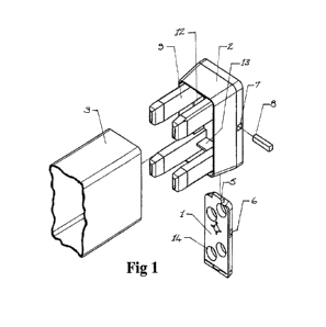
Figure 1 is a composite isometric view of the anchor element, adaptor
element and structural member of the present invention;
Figure 2 is a face view of the interior of the adaptor element;
Figure 3 is a face view of the outer surface of the anchor element;
Figure 4 is a side view of the anchor element of Figure 3;
Figure 5 is a transverse cross-sectional view on A-A of the anchor element of
Figure 3;
Figure 6 is a fragmentary view of one corner of the adaptor element of Figure
2;
Figure 7 is a face view of the outer surface of the anchor element of Figure 3
adapted for the installation of locking provisions;
Figure 8 is a face view of the interior of the adaptor element of Figure 2
adapted for the installation of locking provisions;
Figure 9 is a longitudinal cross-sectional view through a medial plane
parallel
to the greater sides of the adaptor element of Figure 2 said adaptor element
having
been adapted for the installation of locking provisions;
Figure 10 is a superior view of the adaptor element of Figure 2 showing the
use of a security screw to operate locking provisions;
Figure 11 is a superior view of the adaptor element of Figure 2 showing the
CA 03211352 2023- 9- 7
10
use of a key to operate locking provisions;
Figure 12 is a vertical cross-sectional view through a medial plane of a first
method of fixing the anchor element to a surface;
Figure 13 is a fragmentary face view of a second method of fixing the anchor
element to a surface;
Figure 14 is a fragmentary face view of a third method of fixing the anchor
element to a surface;
Figure 15 is a fragmentary vertical cross-sectional view through a medial
plane of the method of fixing of figure 14;
Figure 16 is a side view of an alternative embodiment in which the adaptor
element is pivotally supported to permit the angular displacement of the
structural
member.
With reference to Figure 1, a connection system adaptable to a variety of
applications
comprises an anchor element 1 able to be fixed to a primary structure or
structural member in
a variety of ways, an adaptor element 2 slidingly engaged with the parallel,
angled side edges
of said anchor element and lockable to said anchor element, and a secondary
structural
member 3 engaged with and secured to said adaptor element, said adaptor
element being
made in a range of forms to accommodate secondary structural members of a
variety of
transverse cross-sectional shapes. While it is common for primary structures
and structural
members to be of a vertical orientation and secondary structural members to be
of a
horizontal orientation, other orientations of both may be required, the
present invention being
adaptable to accommodate these.
Said anchor element takes the form of a rectangular block having a ratio of
thickness
to overall width falling in the range 1:7.5 to 1:15.
With additional reference to Figures 3 to 5, said anchor element has formed on
its
upper central edge a toe 5 which engages a complementary recess 20 in the
upper edge of
said adapter element (as depicted in Figure 9), engagement of said toe with
said recess acting
as an indicator of the full seating of said adaptor element on said anchor
element. A plurality
of bores 4 pass through the thickness of said anchor element, two or more of
said bores
accommodating suitable fastenings employed to fix said anchor element to a
surface. In the
preferred embodiment, where said surfaces are of a polymer material or light-
gauge metal
alloy material, said fastenings take the form of self-drilling and self-
tapping screws of the
CA 03211352 2023- 9- 7
11
type commonly known as Tek Screws. Said bores are provided at their outer ends
with
suitable recesses 14 of a diameter and depth to fully accommodate the heads of
said
fastenings. Said anchor element is optionally provided with a generally
centrally-located
bore of suitable diameter passing through its thickness, the axis of said bore
being collinear
with the axis of a complementary bore 21 passing through body 62 of said
adaptor element
such that, when said adaptor element is fully seated on said anchor element, a
single fastener
passing through both said bores being optionally employed to lock said adaptor
element to
said anchor element. Said anchor element is optionally provided with an
elongated recess 6
of square, rectangular or round cross-sectional shape located approximately
medially in one
side and extending inwardly (transversely) from one side for up to 50 per cent
of the width of
said anchor element, said recess coinciding with a complementary aperture 7
formed in the
appropriate side of said adaptor element when said adaptor element is fully
seated on said
anchor element. A rod 8 of a suitable rigid material is inserted through said
aperture and
fully into said recess to lock said adaptor element to said anchor element,
said rod being
retained in place by frictional effects. Said anchor element having been fixed
to a surface
with its inner surface 23 abutting, said adaptor element is fixed to it by
sliding down over
said anchor element a longitudinally-arranged channel (depicted as 21 in
Figure 9) formed in
the flat, inner surface of said adaptor element and having a width and depth
complementary
to those of said anchor element, said sliding engagement being continued until
said toe is
fully engaged with said complementary recess. Sides 22 of said anchor element
are angled in
the manner of the dovetail slideway of a machine tool, making said anchor
element widest at
its outer surface, the sides of said longitudinal channel being angled
similarly, said angled
surfaces acting to retain said adaptor element on said anchor element, the
widths of said
longitudinal channel and said anchor element being such as to just permit said
sliding
engagement.
Said adaptor element having been fixed to said anchor element, the end of a
secondary structural member 3 is inserted into said adaptor element, the
thickness of the
walls of said secondary structural member being accommodated in peripheral
zone 11
between the outer surfaces of outwardly-projecting, rigid fingers 9 positioned
immediately
adjacent and inwardly of the corners of the open end of said adaptor element
and a plurality
of narrow ribs 10 formed on the inner surface of skirt 24 formed around the
periphery of said
adaptor element, said ribs being arranged parallel to the longitudinal axis of
said secondary
CA 03211352 2023- 9- 7
12
structural member. Said fingers, located immediately inwards of the corners of
the open end
of said adapter element, act to guide said secondary structural member into
said peripheral
zone, elastically deflecting as required to accommodate the end thickness of
said secondary
structural member, said ribs acting to increase the frictional engagement of
said secondary
structural member with said adaptor element. Webs 12, 13 fixed to body 62 of
said adapter
element join said fingers and thereby provide bracing. Where more positive
attachment of
said secondary structural member to said adaptor element is required, said
structural member
is optionally bonded into place. Where a tensile force is to be applied to
said structural
member, suitable fastenings are employed to fix said structural member to said
adaptor
element.
With additional reference to Figure 6, where said secondary structural member
forms
the top or bottom rail of a fence, gate or like structure it may be necessary
to have another
secondary structural member neatly abutting its upper or lower surface. As the
adjacent said
skirt of said adaptor element may prevent such abutment, provision is made to
break out a
panel from the appropriate lower or upper said skirt of said adaptor element,
said panels
being rendered readily removable by the provision of suitably located
weakening grooves 19
formed in the inner surface of said skirt. Said panels are broken out simply
by gripping them
with a suitable implement and applying a modest force. Similarly, as the lower
edge part of
said anchor element may prevent such abutment, provision is made to break away
said lower
edge part, said lower edge part being rendered readily removable by the
provision of a
suitably located weakening groove 17 formed in the outer surface of said
anchor element, a
centrally-located recess 16 being provided for the insertion of a suitable
implement to effect
said breaking away.
With reference to Figures 7, 8 and 11, in an alternative embodiment, said
adaptor
element is releasably locked to said anchor element by means of a key (not
shown) inserted
in a keyhole to operate a tumbler mechanism (not shown) accommodated within
boss 26
formed on the interior of said adaptor element. Rotational displacement of
said key and said
tumbler mechanism in the correct sense causes rotation of shaft 27, thereby
displacing tongue
inwardly through aperture 29 provided in the inner wall of said adaptor
element, allowing
said tongue to engage complementary slot 30 provided in the outer surface of
said anchor
element. Location of said tongue in said slot of said anchor element and
removal of said key
acts to securely fix said adaptor element to said anchor element. If
necessary, the end of said
CA 03211352 2023- 9- 7
13
secondary structural member is cut away locally to accommodate said boss. With
reference
to Figure 10, the lock mechanism described in relation to Figure 8 is deleted
and said shaft is
simply turned by a tamper-proof screw of one of the types well known in the
art. Such screw
types include the Two Hole Screw (depicted as 35 in Figure 10), 6-Lobe Star
Drive Screw,
Pin Hex Screw or Tri Slot Screw. The heads of said screws are recessed into
said adaptor
element to prevent their being gripped by pliers or similar tools, said
adaptor element having
been locked to said anchor element in the said way, can only be released using
the
appropriate tool. The locking in place of said adaptor element and, therefore,
said secondary
structural member is useful in situations where some secure form of temporary
barrier or
structure is required to be maintained for some time.
With reference to Figure 9, in another alternative embodiment, said adaptor
element
is releasably locked to said anchor element by means of a plunger 30 passing
through
aperture 33 provided in the inner wall of said adaptor element to enter a
complementary
recess (not shown) formed in the outer surface of said anchor element. Said
plunger is
formed on arm 31 pivotally supported on pivot 32, spring means (not shown)
being provided
to urge said plunger into said recess. Said arm is extended to create
concealed trigger 34
extending downwardly, access to said trigger being obtained through a suitable
slot provided
in the lower surface of said secondary structural member. The latching in
place of said
adaptor element and, therefore, said structural member is useful in situations
where some
form of barrier or structure is required to be temporarily maintained.
With reference to Figure 12, in another alternative embodiment, anchor element
1 is
fixed to metal plate surface 36 by means of a single bolt and nut 37, 38
passing through more
or less centrally-located bore 39 in said anchor element. One or more short
pins 40
protruding inwardly from said anchor element enter complementary bores in said
metal plate
and act to positionally locate said anchor element. Said embodiment provides
ease of
attachment and removal of said anchor element. Obviously, one or more single
light
fastenings passing through said anchor element and tapped into said metal
plate may be used
to stabilise the position of said anchor element in place of said pins, but
with reduced ease of
attachment and removal.
With reference to Figure 13, in another alternative embodiment, anchor element
1 is
fixed to surface 42 by means of two or more short pins 43 with enlarged heads
(depicted in
broken line as 44) passing through keyhole-type apertures in said surface.
Said enlarged
CA 03211352 2023- 9- 7
14
heads are passed through the larger openings 45 of said keyhole apertures,
said anchor
element then being linearly displaced to enter said pins into the narrow parts
of said keyhole
apertures, the lengths of said pins being such as to just provide a working
clearance between
said surface and the undersides of said enlarged heads. Accommodated within
square or
rectangular aperture 47 provided in said surface is blocking piece 49
rotationally supported
from said anchor element on shaft 48, said shaft being rotatable in said
anchor element using
a simple tool.
In the position of said anchor element in which said enlarged
heads are
presented to said larger openings, said blocking piece is positioned parallel
to and adjacent
the upper edge of said aperture. As said anchor element is displaced to enter
said pins into
said narrow parts of said keyhole apertures, said blocking piece is
simultaneously displaced
to a position in which it is parallel to and adjacent the lower edge of said
aperture. Rotation
of said shaft through 90 degrees in the appropriate sense then brings the free
end of said
blocking piece into contact with the upper edge of said aperture, thereby
preventing
displacement of said anchor element to release said headed pins.
In the preferred
embodiment, detents are provided to positively retain said blocking piece in
its un-displaced
and displaced positions. Said embodiment provides ease of attachment and
removal of said
anchor element. Obviously, one or more single light fastenings passing through
said anchor
element and tapped into said surface may be used to lock said anchor element
in place on
said surface, but with reduced ease of attachment and removal.
With reference to Figures 14 and 15, anchor element 1 is fixed to surface 50
by
means of two or more two or more short pins 51 with enlarged heads 53 fixed in
bores 52 in
said anchor element engaging keyhole-type apertures in said surface. Said
keyhole-type
apertures comprise larger openings 55 extending from which are arcuate narrow
parts 56. In
fixing said anchor element to said surface, said enlarged heads are passed
through said larger
openings of said keyhole apertures, said anchor element then being
rotationally displaced to
enter said pins into the narrow parts of said keyhole apertures, the lengths
of said pins being
such as to just provide a working clearance between said surface and the
undersides of said
enlarged heads. In the preferred embodiment, the edges of said heads are
turned down
slightly to provide a frictional engagement with said surface. Rotation of
said anchor
element brings it into a position in which said adaptor element can be fixed
to it, said adaptor
element thus being positioned to receive said secondary structural member,
engagement of
said structural member with said adaptor element preventing rotation of said
anchor element
CA 03211352 2023- 9- 7
15
to release said pins from said keyhole-type apertures. Said embodiment
provides ease of
attachment and removal of said anchor element.
With reference to Figure 16, an alternative embodiment, adaptor element 2 is
fixed to
said anchor element (not shown) in the manner described in relation to Figures
3 to 5, said
channel with angled sides being formed in adaptor element base 57. Formed on
said base are
two outwardly-projecting, vertically-orientated, parallel supporting plates
58, adaptor collar
59 being pivotally supported on said supporting plates on pivot shaft 60.
Secondary
structural member 3 is inserted into said adaptor collar, said adaptor collar
having the rigid
fingers and plurality of narrow ribs formed on the inner surface of the skirt
of said adaptor
collar, said features being generally as described in relation to Figure 2. In
the preferred
embodiment, said supporting plates are made part-circular and of a diameter
and spacing
such that they may be accommodated within said adaptor collar, said adaptor
collar being
enlarged as required to provide accommodation for said supporting plates. The
angular
freedom of movement of said adaptor collar is determined by the length and
shaping of said
supporting plates and the adaptation of said adaptor collar, such as the
cutting away of inner
edges 61.
In alternative embodiments (not shown), said adaptor element is made with a
cavity
shaped to receive secondary structural members of a variety of transverse
cross-sectional
shapes. Such cross-sectional shapes include, square, rectangular, round, oval,
D-shaped,
hexagonal, octagonal, ribbed, grooved or other specialised form.
The fact that mating components of the present invention are drawn to
different
scales is of no significance.
The present invention should be taken to include any feasible combination of
features
described herein.
CA 03211352 2023- 9- 7