Note: Descriptions are shown in the official language in which they were submitted.
WO 2022/192737
PCT/US2022/020047
RACK ASSEMBLY
FIELD OF THE INVENTION
[001] The present invention relates to rack assemblies.
BACKGROUND OF THE INVENTION
[002] Rack assemblies are commonly used to shelve items. They are convenient
because they
can be disassembled and stored in somewhat ergonomic manners. Specifically,
when
disassembled and packaged, the rack assemblies take up relatively little
space, as compared to
shelving units that are of a generally fixed nature. However, although known
rack assemblies are
desirable for this reason, there are improvements that can be made.
Specifically, when rack
assemblies are shipped in bulk, every square inch of space matters. Today's
rack assemblies,
though collapsible, are deficient in this regard and thus leave manufacturers
and those in supply
chains at a disadvantage. Existing racks that can be assembled and
disassembled are sometimes
structurally weak and may wobble, tip or the like. The disclosed concept, as
will be apparent, is
an improvement in this and other regards.
SUMMARY OF THE INVENTION
[003] A collapsible rack assembly is provided. The assembly includes a
vertical support, a first
elongated shelf having a first corner region and a rail extending therefrom,
and a second elongated
shelf including a second corner region having a notch apparatus. The vertical
support is structured
to extend between and support the first and second elongated shelves when the
collapsible rack
assembly is in an ASSEMBLED position. The notch apparatus is configured to
receive the rail in
order to allow the first elongated shelf to nest within the second elongated
shelf when the
collapsible rack assembly is in a COLLAPSED position.
[004] In another aspect of the disclosed concept, a rack assembly is provided.
The rack assembly
includes a first vertical support and a second vertical support; an elongated
shelf having an end
with a first corner region and a second corner region disposed opposite the
first corner region, each
of the first and second corner regions having an opening; and an end cap
coupled to the end of the
elongated shelf, the end cap having first and second thru holes each aligned
with a corresponding
-1 -
CA 03211529 2023- 9-8
WO 2022/192737
PCT/US2022/020047
opening of the elongated shelf and configured to receive a corresponding one
of the first and
second vertical supports.
DESCRIPTION OF THE DRAWINGS
[005] These features and others will become more apparent when read in
conjunction with the
following Figures, in which:
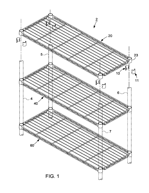
[006] FIG. 1 is a partially exploded front isometric view of a rack assembly,
shown with features
in phantom line drawing, in accordance with one non-limiting embodiment of the
disclosed
concept;
[007] FIGS. 2 ¨ 4 are top plan, side, and front views, respectively, of an
elongated shelf for the
rack assembly of FIG. 1;
[008] FIG. 5 is an enlarged view of a portion of the front view of the
elongated shelf of FIG. 4;
[009] FIGS. 6-8 show different exploded views of portions of the rack assembly
between
ASSEMBLED and COLLAPSED positions;
[0010] FIGS. 9 and 10 show isometric and front views of elongated shelves for
the rack assembly
of FIG. 1 in a COLLAPSED position;
[0011] FIG. 11A is an isometric view of a rack assembly, shown in an ASSEMBLED
position, in
accordance with another non-limiting embodiment of the disclosed concept;
[0012] FIG. 11B is a front view of an elongated shelf for the rack assembly of
FIG. 11A;
[0013] FIG. 12 is an isometric view of a rack assembly in an ASSEMBLED
position, shown
partially exploded, in accordance with another non-limiting embodiment of the
disclosed concept;
[0014] FIG. 13 is an exploded isometric view of a portion of the rack assembly
of FIG. 12;
[0015] FIGS. 14 and 15 are enlarged views of portions of the rack assembly of
FIG. 13;
[0016] FIGS. 16 and 17 are enlarged views of portions of other rack
assemblies, in accordance
with other non-limiting embodiments of the disclosed concept;
[0017] FIGS. 18-21 show exploded and assembled views of different orientations
of multiple rack
assemblies and elongated shelves, in accordance with other non-limiting
embodiments of the
disclosed concept;
[0018] FIG. 22 is an isometric view of another elongated shelf for a rack
assembly, in accordance
with another non-limiting embodiment of the disclosed concept;
-2-
CA 03211529 2023- 9-8
WO 2022/192737
PCT/US2022/020047
[0019] FIG. 23A shows an exploded isometric view of a portion of another rack
assembly, in
accordance with another non-limiting embodiment of the disclosed concept;
[0020] FIGS. 23B and 23C are different enlarged views of the portion of FIG.
23A;
[0021] FIG. 24 is an assembled isometric view of a portion of another rack
assembly, in
accordance with another non-limiting embodiment of the disclosed concept;
[0022] FIG. 25 is an isometric view of another elongated shelf, in accordance
with yet a further
embodiment of the disclosed concept;
[0023] FIG. 26 is an exploded view of another rack assembly, in accordance
with another non-
limiting embodiment of the disclosed concept;
[0024] FIGS. 27 and 28 are different views of portions of the rack assembly of
FIG. 26, shown in
a partially collapsed position;
[0025] FIG. 29 is an enlarged view of a portion of the rack assembly of FIG.
26;
[0026] FIGS. 30 and 31 are different top plan views of portions of the rack
assembly of FIG. 26;
and
[0027] FIG. 32 shows the rack assembly of FIG. 26 in a COLLAPSED position.
-3-
CA 03211529 2023- 9-8
WO 2022/192737
PCT/US2022/020047
DETAILED DESCRIPTION OF THE INVENTION
[0028] Reference to terms such as "left", "right", "top", -bottom", "front"
and "back" are intended
for use in respect to the orientation of the particular feature, structure, or
element within the figures
depicting embodiments of the invention. It would be evident that such
directional terminology
with respect to the actual use of a device has no specific meaning as the
device can be employed
in a multiplicity of orientations by the user or users.
[0029] The description of elements in each figure may refer to elements of
proceeding figures.
Like numbers refer to like elements in all figures, including alternate
embodiments of like
elements.
[0030] FIG. 1 shows a portion of a rack assembly 2, that beneficially is
collapsible into a compact
package for shipping purposes. Rack assembly 2 is useful for storing items in
a home, office,
garage, warehouse, or other facility. In certain examples, a wire decking rack
assembly such as is
depicted is frequently referred to as "a baker's rack." As shown, rack
assembly 2 includes a
plurality of vertical supports 4,5,6,7 (shown in phantom line drawing), a
plurality of press fit
members (two members 10,11 are indicated), and a plurality of elongated
shelves or racks
20,40,60,80 (see FIGS. 6 and 7 for shelf 80). Vertical supports 4,5,6,7, in
certain examples, are
elongated tubular members (or rods, columns, etc.) that may be formed with a
plurality of annular
notches spaced evenly along a length of each vertical support 104. Press fit
members, e.g., wedge
shaped plastic sleeves 10,11, are configured to engage one of the annular
notches and position and
secure the elongated shelves 20,40,60,80 to vertical supports 4,5,6,7.
Additionally, in one example
embodiment, vertical supports 4,5,6,7 and elongated shelves 20,40,60,80 are
metallic.
[0031] Vertical supports 4,5,6,7 may each comprise a plurality of vertical
members, or may be
one unitary member made from a single piece of material (e.g., metal). They
are structured to
extend between and support elongated shelves 20,40,60,80 when rack assembly 2
is in an
ASSEMBLED position. Moreover, for purposes that will be apparent below, each
of elongated
shelves 20,40,60,80 are preferably structured the same.
[0032] Referring to FIGS. 2-5, elongated shelf 20 includes a corner region 22,
a sleeve member
23, and a rail 24 extending from sleeve member 23 (or similar mount) of corner
region 22.
Additionally, it will be appreciated that press fit members 10,11 are
configured to be coupled to
-4-
CA 03211529 2023- 9-8
WO 2022/192737
PCT/US2022/020047
one another, be disposed within sleeve member 23, and receive vertical support
6 in order to secure
vertical support 6 within sleeve member 23 in a press fit manner.
[0033] As shown in FIG. 4, corner region 22 further has a notch apparatus in
the form of a bent
rail 26. Bent rail 26 is advantageously structured to receive a rail of one of
elongated shelves
40,60,80, such as by forming or creating a notch or inset (such as where a
rail or other portion of
another shelf is located in the inset or notch created by the bent rail 26,
extending generally
transverse or perpendicular thereto) in order to allow elongated shelf 20 to
nest within the other
elongated shelf 40,60,80 when the collapsible rack assembly 2 is in a
COLLAPSED position. This
aspect of rack assembly 2 advantageously allows for improved space savings, as
compared to
known rack assemblies. In this manner, manufacturers will be able to ship more
rack assemblies
in transit and store owners will be able to stack more collapsed rack
assemblies on shelves, to name
a few of the advantages. This improvement in the flow of commerce translates
into a cost savings
for the parties involved.
[0034] Referring to FIG. 5, bent rail 26 preferably includes a first segment
30, a second segment
31 parallel to the first segment 30, and a third segment 32 connecting the
first and second segments
30,31. As shown, the third segment 32 extends at an angle 33 greater than
ninety degrees from
the first segment 30. This construction allows for the aforementioned nesting
capability, as will
be appreciated below.
[0035] Additionally, as shown in FIG. 4, elongated shelf 20 further has
another corner region 27
located opposite corner region 22 and having a notch apparatus in the form of
a bent rail 28 which
is symmetric to the bent rail 26 of corner region 22. It will be appreciated
that the other end of
elongated shelf 20 has symmetric bent rails as well, which simplifies
orienting rack assembly 2 in
the COLLAPSED position.
[0036] As shown in FIGS. 6-10, elongated shelves 40,60 may be sandwiched
between elongated
shelves 20,80 when rack assembly 2 is in a COLLAPSED state. This is shown most
clearly in
FIG. 9, although since all elongated shelves 20,40,60,80 are preferably
structured the same, it will
be appreciated that the numbering of shelves arc interchangeable. As shown in
FIG. 9, rail 44 of
elongated shelf 40 is nested within notch apparatus (e.g., bent rail 26) of
elongated shelf 20. This
translates into a significant space savings. More specifically, and referring
to FIG. 10= elongated
shelves 40,60 are structured to nest within elongated shelves 20,80 in the
COLLAPSED position
-5-
CA 03211529 2023- 9-8
WO 2022/192737
PCT/US2022/020047
such that a combined height HI of elongated shelves 20,40,60,80, when nested,
is less than a
combined height 4*H2 of elongated shelves 20,40,60,80, individually, where H2
is the height of
each of elongated shelves 20,40,60,80 individually.
[0037] FIG. 11A shows another collapsible rack assembly 102, in accordance
with another non-
limiting embodiment of the disclosed concept, wherein like numbers represent
like features. FIG.
11B shows a front view of elongated shelf 120. It will be appreciated with
reference to FIG. 11B
that corner region 122 has a cutout and the notch apparatus is in the form of
an insert 126 coupled
to the rack, such as the wire frame that forms a cutout. Insert 126 may be
made of a different
material than the rest of elongated shelf 120. As shown, insert 126 has a
groove (or inset or notch)
130 for receiving a rail of elongated shelf 140 in a similar manner in which
bent rail 26 (FIG. 9)
of elongated shelf 20 (FIG. 9) received rail 44 (FIG. 9) of elongated shelf 40
(FIG. 9).
Accordingly, stacking advantages discussed above with reference to rack
assembly 2 also apply to
rack assembly 102.
[0038] FIG. 12 shows another rack assembly 202 in accordance with another
embodiment of the
disclosed concept, wherein like reference numbers represent like features.
FIG. 13 shows an
exploded view of a portion of the rack assembly 202 of FIG. 12. As shown,
elongated shelf 220
has an end 222 with opposing corner regions 224,226 that each have a
corresponding opening
225,227. Additionally, rack assembly further has a pair of end caps 235,245
coupled to elongated
shelf 220 (see also end caps 255,256,265,266,275,276,285,286 in FIG. 12 for
elongated shelves
250,260,270,280). In one example embodiment, elongated shelves
220,250,260,270,280, vertical
supports 204,205,206,207, and end caps 235,245.255,256,265,266,275,276,285,286
are all
metallic.
[0039] Each of elongated shelves 220,250,260,270,280 is configured to couple
with end caps
235,245,255,256,265,266,275,276,285,286 in order to reduce an overall
footprint. In particular,
the removable end caps allow for the vertical supports to be stacked on the
elongated shelves when
packaged, and reduce the overall height of the packaging, and allowing for
more packaged rack
assemblies 202 to be shipped in a shipping container.
[0040] As shown in FIG. 12, end cap 235 has first and second thru holes
236,237 that are each
aligned with a corresponding opening 225,227 of elongated shelf 220 and
configured to receive
vertical supports 206,207. It will be appreciated that end cap 245 likewise
receives vertical
-6-
CA 03211529 2023- 9-8
WO 2022/192737
PCT/US2022/020047
supports 204,205 in a similar manner. Also shown in FIG. 12, end cap 235 has a
thru hole 238
(and another thru hole disposed proximate thru hole 236) located proximate
thru hole 237. Rack
assembly 202 further has a pair of fasteners (e.g., without limitation, one
set screw 244 is indicated)
configured to extend through a corresponding one of the thru holes 238 (and
the other opposing
thru hole, not shown) of end cap 235 and be located proximate the vertical
supports 206,207 in
order to more securely maintain rack assembly 202 in an ASSEMBLED position.
[0041] Referring to FIGS. 14 and 15, rack assembly 202 further includes a
number of inserts
240,246 each coupled to the vertical supports 206,207. In one example
embodiment, the inserts
240,246 are each coupled to an interior of the vertical supports 206,207.
Insert 240 may be a cap
that is located at a top of the rack assembly 202 when rack assembly 202 is in
an ASSEMBLED
position and disposed on a horizontal ground. See, for example, FIG. 12. Three
other inserts are
also shown in this FIG., but only insert 240 is indicated. Insert 240, and the
other three inserts,
may function to provide surfaces for a table to advantageously be formed on
rack assembly 202.
Additionally, as shown in FIG. 14, insert 240 has a number of ridges 241-1,241-
2,241-3 that may
be configured to be located in corresponding grooves of vertical support 206
in order to maintain
insert 240 in a fixed position within vertical support 206. As insert 240
functions to provide a top
of rack assembly 202, insert 246 shown in FIG. 15 functions to provide a foot
for rack assembly
202, so that it can more stably be positioned in an upright manner when in an
ASSEMBLED
position and located on a horizontal ground. As shown in FIG. 12A, three other
feet (not labeled)
are also provided with rack assembly 202. Continuing to refer to FIG. 15, an
externally threaded
sleeve 247 may be provided in order to more securely couple insert 246 to
vertical support 207.
[0042] An insert 342,442 may also be threadably coupled to an interior of a
vertical support
306,406-1,406-2, as shown in FIGS. 16 and 17. In the case of the embodiment of
FIG. 16, insert
342, which functions as a top, is relatively securely coupled by virtue of the
threads. Regarding
the embodiment of the rack assembly of FIG. 17, insert 442 advantageously
allows for segment
406-1 of the vertical support to be more stably connected to segment 406-2,
where before they
might only have been maintained at such a joint via a press fit connection.
[0043] FIGS. 18 and 19 show assembled and exploded views, respectively, of
rack assemblies 502
and an elongated shelf 520 configured to be coupled in order for more
versatile applications to be
provided, such as further storage capabilities. FIGS. 20 and 21 show assembled
and exploded
-7-
CA 03211529 2023- 9-8
WO 2022/192737
PCT/US2022/020047
views, respectively, of rack assemblies 502 and an elongated shelf 520
configured to be coupled
in order for more versatile applications to be provided, such as further
storage capabilities. In
some configurations, connectors, such as fasteners, may be used to join the
shelves 520 and/or
racks 502. For example, one or more apertures may be provided in the end caps
245 (see FIG. 13),
whereby aligned end caps (such as placed side by side or end to end) may be
joined, such as with
one or more fasteners (such as a nut/bolt, etc.)
[0044] FIG. 22 shows an isometric view of another elongated shelf 620. As
shown, the elongated
shelf 620 includes a first half portion 621, a second half portion 623, and an
elongated sleeve 625
for connecting the first and second half portions 621,623. Accordingly, it
will be appreciated that
yet an even greater space savings can be afforded for rack assemblies
including elongated shelves
structured the same as elongated shelf 620, in that different portions 621,623
can be overlaid on
top of one another in order to further reduce the footprint of a corresponding
rack assembly.
[0045] FIG. 23A shows a portion of another rack assembly 702, wherein like
reference numbers
represent like features. As shown, end cap 735 has an aperture 738 disposed
proximate thru hole
737, and a further aperture disposed on an opposing side (not shown).
Referring to FIGS. 23B and
23C, elongated shelf 720 has a number of plates 740,741,742 coupled to corner
region 726. Plate
742 has a push pin 743 extending outwardly therefrom and being biased away
from elongated shelf
720. Push pin 743 is configured to extend through thru holes of plates
740,741, which are securely
maintained on corner region 726 by engaging and being disposed between
opposing wires of
corner region 726. Furthermore, it will be appreciated that push pin 743 is
configured to extend
through aperture 738 of end cap 735 in order to securely maintain and connect
end cap 735 with
elongated shelf 720. Opposing corner region 724 (FIG. 23A) and end cap 745
(FIG. 23A) are
similarly structured and coupled in this pin to aperture manner, and so are
other end caps and
elongated shelves of rack assembly 702 (not shown). Accordingly, if end cap
735 is caused to
slide with respect to elongated shelf 720, the engagement between push pin 743
and plates 740,741
advantageously prevents decoupling.
[0046] FIG. 24 shows yet a further embodiment of the disclosed concept,
wherein a portion of a
rack assembly 802 is shown. As shown, rack assembly 802 has an elongated shelf
820 which is
devoid of notches proximate end portions that couple to end caps ¨ such as by
not including an
end rail at all, but wherein the end cap forms the end portion of the rack.
-8-
CA 03211529 2023- 9-8
WO 2022/192737
PCT/US2022/020047
[0047] In one configuration, as illustrated in FIG. 25, the elongated shelf
920 may define having
cutout portions proximate corner regions 922,924,926,928, which regions accept
the end caps,
including the associated sleeves. The resulting reduced thickness, as
discussed above,
advantageously allows elongated shelf 920 to be shipped with a reduced
footprint, and may allow
end caps to either be fixedly attached thereto, or otherwise be connected
thereto during shipping
and shelving.
[0048] One aspect of this version of the invention is that elongated shelf 820
and other elongated
shelves of rack assembly 802 can be stacked with a minimal footprint.
Additionally, because of
the reduced thickness proximate end portions of elongated shelf 820, end caps
may be able to be
fixedly attached to end portions, or otherwise connected while elongated shelf
820 is being
shipped, thereby saving assembly time downstream. For example, in one packing
configuration,
the end caps are removed from a first rack, allowing it to be placed between
second and third racks
having the end caps attached thereto (wherein the reduced thickness of the
first rack allows it to
be placed between the second and third racks without an increase in stack
dimension due to the
space between the second and third racks created because of the increased
dimension of the end
cap/sleeves of the second and third racks).
[0049] In particular, FIG. 26 shows an exploded view of another rack assembly
1002, which
includes vertical supports 1004-1,1005- 1,1006- 1,1007-1,1004-
2,1005-2,1006-2,1007-2,
elongated shelves 1020,1040,1060,1080,1090, and end caps
1025,1026,1085,1086,1095,1096.
FIGS. 27 and 28 show different partially exploded views of the rack assembly
1002. As will be
appreciated below, rack assembly 1002 is configured to collapse in a
relatively ergonomic manner.
FIGS. 29-31 show different views of portions of the rack assembly of FIG. 26,
and FIG. 32 shows
an isometric view of rack assembly 1002 in a COLLAPSED position. As shown, the
vertical
supports (shown but not labeled) are enclosed by the elongated shelves 1020,
1080,1090 without
any being sacrificed, as can be appreciated by viewing the end caps. As shown,
with two end caps
1085,1095 removed and coupled externally, all of the elongated shelves (e.g.,
including shelves
1040,1060 from FIG. 26. which fit between shelves 1020,1080) can fit in the
collapsed assembly.
Additionally, as shown in FIGS. 29-31, the collars of end caps 1086 have
notches in order to allow
the shelves that have the removed end caps (e.g., end caps 1085,1095, see FIG.
32) to be slid into
the notch a predetermined distance, so that the side rails fit into the slot
in the collar of the end cap
-9-
CA 03211529 2023- 9-8
WO 2022/192737
PCT/US2022/020047
of the shelf above it. It will be appreciated that the two collars of end cap
1086 and the two collars
of end cap 1096 have such notches, as shown in FIG. 32. In one embodiment,
utilizing this notched
collar configuration, the shelves that have the removed end caps need to only
be slid over or offset
by 0.25" to align the side rails into the notches, thus facilitating nearly
aligned stacking of the
shelves, but at the same time allowing the shelves without the end caps to be
located in between
the pairs of shelves with the end caps (this .25 inch offset is much smaller
than other stacking
configurations, such as the configuration where a notch is located in the wire
of the decking or in
an insert adjacent to the collar, in versions described above, and is much
less in stacking height as
compared to existing prior art where the shelves are directly placed on top of
one another).
[0050] As illustrated in FIG. 1, in one configuration the sleeves 23 may
extend upwardly above
and downwardly below a top and/or bottom of the shelf. However, in other
embodiments, the top
and/or bottom of the sleeve (such as integrated into the end cap) might be
generally flush with the
top (and/or bottom) thereof, such as illustrated in FIGS. 24-25, and also in
FIG. 13 (and whereby
the cap or insert 240 (see FIG. 14) may merely be used to close the opening in
the end cap or
sleeve, with the top of the cap being generally flush with the top of the end
cap.
[0051] FIG. 24 also illustrates how the rail portions of the shelf, such as
the side rails (but also the
end rails, as in the configuration illustrated in FIG. 1) may be solid rails,
rather than formed from
wires (such as parallel wires with an intermedia Z-wire).
[0052] As indicated above, the end caps may be generally permanently mounted
to one or more
of the shelves, but in other embodiments, they may be removably attached, such
as to for shipping
and storage. In such a configuration the end caps might be connected to the
shelf by one or more
fasteners (nuts/bolts, push-pins, etc.)
[0053] This description uses examples to describe embodiments of the
disclosure and also to
enable any person skilled in the art to practice the embodiments, including
making and using any
devices or systems and performing any incorporated methods. The patentable
scope of the
disclosure is defined by the claims and may include other examples that occur
to those skilled in
the art. Such other examples arc intended to be within the scope of the claims
if they have structural
elements that do not differ from the literal language of the claims, or if
they include equivalent
structural elements with insubstantial differences from the literal language
of the claims. For
example, it will be appreciated that suitable alternative embodiments of the
disclosed concept
-10-
CA 03211529 2023- 9-8
WO 2022/192737
PCT/US2022/020047
include elongated shelves have different aspects from any of the different
aforementioned
embodiments.
-11 -
CA 03211529 2023- 9-8