Note: Descriptions are shown in the official language in which they were submitted.
CA 03212125 2023-08-29
WO 2022/190050
PCT/IB2022/052195
1
Animal husbandry system and illumination unit suitable for the system
The present invention relates to an animal husbandry system.
Such systems are widely known in the art. Illumination plays an important role
in such
systems. W02015/104250 discloses a method and system of rearing chickens in
which
a plurality of cameras is provided in a shed for monitoring the shed floor and
adjusting
the shed floor illumination. W02014/118788 discloses an optical monitoring
system for
livestock in which various activities may be measured to determine the health
state of the
population of animals. Generally, an area with animals should be illuminated
in
dependence on the time of day, the season, the weather, etcetera.
There is a need for an improved system with an efficient illumination setting
and calibration mechanism.
It is an object of the present invention to provide such an improved system.
The invention achieves the object at least in part by means of a system
according to claim 1, in particular an animal husbandry system, wherein a
group of
animals can move about freely in an area, the system comprising at least one
illumination
unit, each illumination unit comprising a mounting structure provided with a
number of
illumination elements, each arranged for illuminating a respective subarea,
the system
also being provided with at least one camera arranged for monitoring a number
of
subareas, wherein the camera(s) is (are) arranged for repeatedly determining
the
illumination intensity at one or more reference surfaces in the area, the
system further
comprising control means, operatively connected to the illumination elements
and to the
camera(s), the control means being programmed for adjusting the illumination
elements,
based upon the determined illumination intensity at the reference surface(s),
in such a
way that a predetermined desired illumination intensity pattern is achieved in
the area.
In this way, a highly useful, versatile and user-friendly system is realized.
The invention is based on the insight that a very simple, yet efficient and
automated
setting and calibration of the illumination intensity in an area with a group
of animals can
be achieved by making use of reference surfaces, such as, for example, body
parts of
the animals themselves. Such a reference surface is easy to use and can be
used
repeatedly. No additional sensors are needed.
The invention further relates to an illumination unit suitable for use in the
system, wherein a camera is provided on the mounting structure of the
illumination unit.
Thus, a very efficient and practical, but also versatile, yet compact
illumination unit is
.. provided.
CA 03212125 2023-08-29
WO 2022/190050
PCT/IB2022/052195
2
Suitable and advantageous embodiments are described in the dependent
claims, as well as in the description below.
According to a first embodiment of the invention, the reference surface(s)
is/are movable. A movable reference surface can not only be used repeatedly,
but also
by more than one camera. This improves the efficiency of the system.
In a further embodiment of the system, the reference surface(s) is (are)
chosen on the body of at least one of the animals. This is a simple, yet
highly practical
implementation, as the animal(s) are likely to move about in most of the area.
Advantageously, if the animals are cows, the reference surface(s) is (are)
chosen on the back of the cow(s). It has been found that this body part of the
cow, which
is normally moved at a leisurely pace, is easily and reliably detectable by
the camera(s)
and therefore highly suitable as a reference surface.
In a further embodiment of the system, wherein an unmanned vehicle can
be moved about in the area, the reference surface(s) is (are) being chosen on
the
unmanned vehicle. Such a vehicle, for example used for cleaning purposes, will
normally
move about and visit each and every corner of the area, making it also
suitable to serve
as a reference surface.
According to a further embodiment, the illumination elements in the system
each comprise an LED module. This is a straightforward but highly practical
implementation.
In yet a further embodiment, the control means are programmed for
adjusting at least a number of the illumination elements periodically. This
ensures an
efficient and automated calibration of the illumination elements.
Advantageously, the control means are programmed for adjusting at least a
number of the illumination elements only if at least a minimum threshold
difference
between the determined illumination intensity in a subarea and the respective
predetermined desired illumination intensity in that subarea has been
established during
at least a minimum threshold time. In this way, sudden, short disturbances of
the
predetermined desired illumination intensity pattern (cause e.g. by a cloud
passing by)
are filtered out, thus eliminating unwanted, superfluous adjustments of the
illumination
elements.
In a still further embodiment of the system, wherein LED modules of
different colours are used, the camera(s) is (are) used for determining the
illumination
intensity of said different colours at the one or more reference surfaces in
the area, the
control means adjusting the illumination elements accordingly. Optimal use of
the
CA 03212125 2023-08-29
WO 2022/190050
PCT/IB2022/052195
3
camera(s) is thus made, leading to a precise adjustment.
In an embodiment of the illumination unit for use in the system, the
illumination elements are arranged to illuminate subareas of the area in a
substantially
non-overlapping manner. This facilitates the achieving of the predetermined
desired
illumination intensity pattern and enhances the efficiency of the system.
In yet another embodiment, the illumination elements are each mounted on
the mounting structure under a different angle, so as to achieve the
illumination of the
respective subareas. This is a technically simple but effective solution.
Advantageously, the illumination of the subareas is realised with the aid of
lenses. This constitutes an efficient implementation.
In a further embodiment, the mounting structure is provided with cooling
fins. In this way, the illumination unit can be efficiently cooled.
According to yet another embodiment, the camera(s) is (are) mounted
substantially in the middle of the mounting structure, between the
illumination elements.
This is a practical implementation which enables the efficient determination
of the
illumination intensity.
The invention will now be further explained with reference to the following
Figures, which schematically illustrate the system and the illumination unit
according to
the invention.
Figure 1 shows a shed with a system according to the invention;
Figure 2 shows a first view of an illumination unit according to the
invention;
Figure 3 shows a second view of an illumination unit according to the
invention;
Figure 4 shows an illumination unit with light beams.
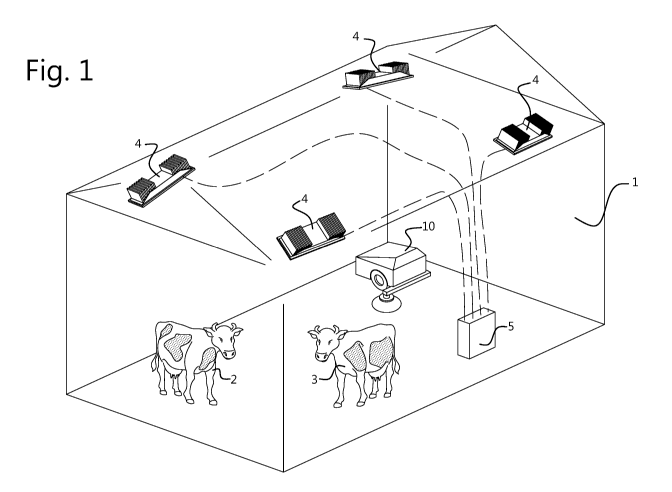
Figure 1 shows an animal husbandry system with a stable or shed or barn
1 wherein a group of animals 2, 3 can move about freely. In the example shown
the
animals are cows. Of course, the invention can also be applied to an animal
husbandry
system involving other animals, such as goats, pigs, horses, chickens,
turkeys, etcetera.
The shed 1 can also be a structure with, for example, a partly open roof. The
system
according to the invention can in principle also be applied in an open area
like a meadow
or pasture with cattle fences.
When keeping animals 2, 3, it is often desirable to provide a specific
illumination. For example, the animals' diurnal rhythm can be influenced by
providing a
daylight type of illumination during a certain number of hours. Also, a
nocturnal
illumination may be provided, which does not disturb the animals, e.g. red
night light in a
cow shed 1, which still enables the observation of the animals 2, 3 at night.
CA 03212125 2023-08-29
WO 2022/190050
PCT/IB2022/052195
4
Generally, it is desirable to provide a constant illumination intensity, not
only
for animal welfare, but also for energy efficiency reasons. Moreover, this
facilitates the
monitoring of the animals 2, 3 by enabling a uniform image quality. It is
known to provide
a certain predetermined desired illumination intensity pattern in an area 1
where animals
2, 3 are held. Such an illumination pattern must be predetermined, set and
maintained by
means of calibration and adjustment in dependence on and in reaction to
external
influences, e.g. the time of day, the season, the weather, temporary external
light sources,
full moon. Furthermore, in almost every practical stable configuration,
overlapping light
beams occur, creating undesirable overlit spots.
The invention provides an improved system with an efficient and precise
illumination setting and calibration mechanism. In the shed 1 a plurality of
illumination
units 4 is provided, suitable for illuminating respective different regions of
the area or shed
1. A control unit 5 with processing means is also provided, operatively
connected to the
illumination units 4. The control unit 5 may comprise a computer or any
processing
means. It can also be located at a distance from the shed 1.
The illumination units 4 are provided with a camera 6 arranged for
monitoring a region or a subarea or a number of subareas of the shed 1, as
will be
described below. Of course, other optical sensors can be used also. The
illumination units
4 with their cameras 6 are provided in such a way that, collectively, they are
suitable for
illuminating and monitoring substantially the complete shed 1, particularly
the animals 2,
3 and the shed floor. The illumination units 4 can be provided in the shed 1
above the
animals 2, 3, as shown in Figure 1, or on the walls of the shed 1. They are
positioned and
oriented in such a way that all relevant subareas of the area 1 can be
illuminated. In case
the invention is used in a pasture, for example for night illumination, the
illumination units
4 may be provided on the fences, at a sufficient height above the ground.
As will be elucidated further below with reference to Figures 2, 3 and 4, the
illumination units 4 are furthermore provided with a mounting structure 7
provided with a
number of illumination elements 8, each arranged for illuminating a respective
subarea of
the shed 1. The subareas can slightly overlap, but they are substantially
different. In this
way, a very precise illumination pattern can be achieved in the whole area 1.
In accordance with the invention, the camera(s) 6 is (are) arranged for
repeatedly determining the illumination intensity at one or more reference
surfaces in the
area 1. These reference surfaces are chosen in such a way that their colour is
known, so
that they can be used to calibrate the illumination. Knowing the exact colour
of the
reference surface and the shutter time of the camera 6, the greyness of the
relevant
CA 03212125 2023-08-29
WO 2022/190050 PCT/IB2022/052195
image pixels can be determined, and thus the illumination intensity. The
reference
surface(s) are preferably movable.
The control means 5 are operatively connected to all the illumination
elements 8 and to the camera(s) 6. They are programmed for adjusting the
illumination
5
elements 8, based upon the determined illumination intensity at the reference
surface(s),
in such a way that a predetermined desired illumination intensity pattern is
achieved and
maintained in the area 1. The pattern can, of course, vary in time. A regular
calibration
with the aid of the reference surface(s) ensures that the illumination pattern
remains
correct in the whole area 1 in the course of time.
The reference surface(s) can be chosen on the body of at least one of the
animals 2, 3. This is advantageous, as the animal(s) 2, 3 are likely to move
about in most
of the area 1, so that a good calibration is achieved throughout the area 1.
In case the
animals are cows 2, 3, the reference surface(s) is (are) chosen on the back of
the cow(s),
for example white spots. It has been found that this body part of the cow 2,
3, which is
normally moved at a leisurely pace, is easily and reliably detectable by the
camera(s) 6
and therefore very suitable as a reference surface for calibrating the system.
White parts
of the skin on the back of the cows 2, 3 are particularly suitable, because
their colour
remains fairly constant in the course of time, unlike, for example, a
(stationary) white
reference surface accumulating dust and dirt.
An unmanned vehicle 10, for example used for cleaning purposes and
known as such, can be moved about in the area 1 by means of the control means
5. In
that case, the reference surface(s) can also be chosen on the unmanned vehicle
10. An
upper surface (well visible for the camera(s) (6)) with a known colour is
suitable for this.
The unmanned vehicle 10 will normally move about with the aid of its
navigation system
and visit each and every corner of the area 1, making it also suitable to
serve as a
reference surface for calibration purposes. The vehicle 10 can comprise
sucking means
suitable for sucking up dirt and a collector for collecting the dirt. Its
drive means can be
charged at a base station in, at or near the shed 1 with means for charging
the vehicle's
batteries (not shown, known as such).
Fixedly installed reference surfaces would also be possible in theory, but
the system according to the invention with its movable reference surfaces does
not need
such additional hardware.
The control means 5 are programmed for adjusting at least a number of the
illumination elements 8 periodically. This ensures an efficient and automated
calibration
of the system.
CA 03212125 2023-08-29
WO 2022/190050
PCT/IB2022/052195
6
The control means 5 are also programmed for adjusting at least a number
of the illumination elements 8 only if at least a minimum threshold difference
between the
determined illumination intensity in a subarea and the respective
predetermined desired
illumination intensity in that subarea has been established during at least a
minimum
threshold time. In this way, sudden, short disturbances of the predetermined
desired
illumination intensity pattern (cause e.g. by a cloud passing by) are filtered
out, thus
eliminating unwanted, superfluous adjustments of the illumination elements 8.
In Figure 2 a first view of the illumination unit according to the invention
is
shown. It is a perspective view of the top side. Figure 3 shows a second view
of the
illumination unit according to the invention. This is a perspective view from
below.
The illumination unit 4 has a mounting structure 7, on the upper side of
which cooling fins 11 for an efficient cooling of the unit 4 are provided. On
the bottom side
of the mounting structure 7 the illumination elements 8 and the camera 6 are
provided.
Typically, the illumination elements 8 each comprise an LED module. This
constitutes a
straightforward, yet highly practical implementation.
For example, two 3-by-3 arrays of illumination elements 8 are mounted on
the mounting structure 7. The illumination elements 8 are each mounted on the
mounting
structure 7 under a different angle, so as to achieve the illumination of the
respective
subareas. This is a technically simple but effective solution. Alternatively
(not shown in
the Figures), the illumination elements 8 can be simply mounted on the
mounting
structure 7 in a parallel fashion, lenses being used to provide the required
different angles
of the light beams.
The camera(s) 6 is (are) mounted substantially in the middle of the mounting
structure 7, between the illumination elements 8. This is a practical
implementation which
enables the efficient determination of the illumination intensity. Typically,
one camera 6
is provided per illumination unit 4, suitable for monitoring substantially all
of the subareas
illuminated by the illumination elements 8 of the respective illumination unit
4. But, of
course, other configurations are also possible.
In the example shown, there are four illumination units 4, each covering
roughly one fourth of the total area 1. The chosen configuration obviously
depends on the
shape of the area or shed 1.
In an embodiment wherein LED modules of different colours are used, the
camera(s) 6 is (are) used for determining the illumination intensity of said
different colours
at the one or more reference surfaces in the area 1, the control means 5
adjusting the
illumination elements 8 accordingly. Optimal use of the camera(s) 6 is thus
made, leading
CA 03212125 2023-08-29
WO 2022/190050
PCT/IB2022/052195
7
to a precise adjustment.
In Figure 4 an illumination unit 4 with light beams 9 is depicted in a
perspective view from below.
As illustrated, in the illumination unit 4, the illumination elements 8 are
arranged to illuminate subareas of the area 1 in a substantially non-
overlapping manner.
This facilitates the achieving of the predetermined desired illumination
intensity pattern
and enhances the efficiency of the system.
The illumination of the subareas can best be realised with the aid of lenses.
This constitutes an efficient implementation. For example, in case the
illumination
elements 8 are mounted on the mounting structure 7 under different angles, the
outer
illumination elements 8 naturally illuminate a greater surface than the inner
ones, as can
be seen in Figure 4. To compensate for this, lenses can be used, in a manner
known per
se.
Alternatively, in case the illumination elements 8 are mounted on the
mounting structure 7 in a parallel fashion, lenses can be used to provide the
required
different angles of the light beams 9.
Should an illumination overlap occur somewhere, for example if two
illumination elements 8 cover a same subarea, then the system solves this, as
soon as
the measurements in the reference surfaces indicate that overlapping light
beams 9
occur. The undesirable overlit spots are automatically eliminated by the
control means 5.
Alternatively, highlighting a certain subarea is also possible, if the
predetermined desired
illumination intensity pattern requires this.
As an additional calibration possibility, all illumination elements 8 can be
activated simultaneously, for example at night. The resulting known light
intensity can be
used as a reference.
Thus, the system is suitable for adjusting repeatedly and automatically,
based upon the determined illumination intensity at the (movable) reference
surface(s),
at least those respective illumination element(s) 8 for the respective
subarea(s) where
the illumination intensity has been found to deviate from the desired
predetermined
illumination intensity pattern.