Note: Descriptions are shown in the official language in which they were submitted.
SINKS AND METHODS OF MAICING THE SAME
boom
TECHNICAL FIELD
[0002] The present technology is generally related to sinks and methods
for making the
sinks.
BACKGROUND
[0003] Generally, sinks have been used for residential and commercial
kitchens and
bathrooms because they can contain fluid and/or materials in their interior
space and operations
can be performed therein such as cleaning and washing dishes, pots, utensils,
etc. and preparing
food. Modem sinks add both functionality and decorative decor and are
manufactured from many
materials and in many designs. In the current marketplace, stainless steel
sinks are particularly
desirable. Most applications utilize fairly standard sized sinks to
accommodate the limitations of
existing spaces and to reduce the cost of pure custom designed furniture and
plumbing work.
100041 Prior art kitchen and bathroom sinks are often installed in
cabinets and are typically
mounted to the countertop via drop in, as under mount or a flush mount,
described as the
relationship between the rim of the sink and the countertop. Typically, prior
art sinks have a rim
1
or flange that is flat, thin and narrow with rounded edges. Drop in sinks are
placed through a pre-
cut hole in the countertop with the flange or lip around the sink providing a
substantial portion of
the support. Common problems of drop in sinks include improper seating of the
flange in the pre-
cut countertop, gaps between the flange and the countertop and insufficient
flange support for the
weight of the basin.
[0005] In addition, materials and conventional sink manufacturing
methods have inherent
limitations on the suitability and sustainability of many sink designs for
drop in sinks. For example,
stainless steel sinks are traditionally stamped from sheet metal or punched
from a mold, resulting
in rounded or beveled edges. This rounded edge feature creates undesirable
gaps between the edges
of the sink and the countertop.
[0006] Still further, with limited counter space in many homes, home
owners are using the
sink space for preparing food. Thus, the size of the inner space of the sinks
is important based on
the needs of the homeowner and some sinks may include a divider for such
purposes. Current
manufacturing processes of sinks with dividers to form two separate basins
have compromised the
sustainability and durability of such metal sinks.
[0007] Moreover, because counter space is limited and sink space has
become useful for
food preparation a multi-workstation sink that can perform different functions
is desired.
Accordingly, it is desirable to provide a durable and sustainable sink unit
with a novel rim or flange
for mounting with the option of a divider in the basin to form multiple basins
for different uses
and adapted to be used as a multi-workstation sink.
2
Date Recue/Date Received 2023-09-20
SUMMARY
[0008] The techniques of this disclosure provide a sink, and methods of
making a durable
and sustainable sink, which can be firmly attached to a countertop of a
cabinet or any other fixtures,
which provides at least two basins without substantially decreasing the volume
of the sink, and
which functions as a multi-workstation sink.
[0009] In accordance with aspects of the disclosure, a sink includes a
bottom surface
forming an opening for drainage therein, a first sidewall, a second sidewall,
a third sidewall, and
a fourth sidewall, each of which is extended from the bottom surface, and a
ledge fixedly attached
to top ends of the first, second, third, and fourth sidewalls. The bottom
surface and the first, second,
third, and fourth sidewalls have a same thickness, and a thickness of the
ledge is different from the
thickness of the bottom surface.
[0010] In various embodiments, the thickness of the ledge is greater
than or equal to 3
millimeters.
[0011] In various embodiments, the thickness of the bottom surface is
less than or equal to
1.6 millimeters.
[0012] In various embodiments, the ledge includes first, second, third,
and fourth parts,
which correspond to the first, second, third, and fourth sidewalls,
respectively.
[0013] In various embodiments, an outer part of the ledge is beveled.
[0014] In various embodiments, the sink further includes a divider
fixedly attached to a
linear opening in the first and third sidewalls and the bottom surface.
[0015] In various embodiments, a width of the divider is greater than or
equal to 3 mm.
3
Date Recue/Date Received 2023-09-20
[0016] In various embodiments, the divider is welded to the linear
opening.
[0017] In various embodiments, the sink further includes at least one
floating ledge on two
facing sides of the first, second, third, and fourth sidewalls.
[0018] In various embodiments, the floating ledge is substantially
parallel with the bottom
surface.
100191 In accordance with aspects of the disclosure, a method for
manufacturing a sink
includes cutting a first metal to form a bottom surface, a first sidewall, a
second sidewall, a third
sidewall, and a fourth sidewall, cutting an opening for drainage in the bottom
surface, folding
boundaries between the bottom surface and each of the first, second, third,
and fourth sidewalls,
welding an edge of each pair of adjacent two sidewalls of the first, second,
third, and fourth
sidewalls so as to make the first, second, third, and fourth sidewalls upright
from the bottom
surface, and welding four pieces of a second metal different from the first
metal used in the cutting
to make a ledge having first, second, third, and fourth parts, welding the
ledge to top ends of the
first, second, third, and fourth sidewalls. The bottom surface and the first,
second, third, and fourth
sidewalls have a same thickness, and a thickness of the ledge is different
from the thickness of the
bottom surface.
[0020] In various embodiments, the thickness of the ledge is greater
than or equal to 3
millimeters.
[0021] In various embodiments, the thickness of the bottom surface is
less than or equal to
0.16 millimeters.
4
Date Recue/Date Received 2023-09-20
[0022] In various embodiments, the ledge includes first, second, third,
and fourth parts,
which correspond to the first, second, third, and fourth sidewalls,
respectively.
10023] In various embodiments, the method further includes beveling an
outer part of the
ledge.
[0024] In various embodiments, the method further includes cutting off a
linear opening in
the first and third sidewalls and the bottom surface, and welding a divider
into the linear opening.
[0025] In various embodiments, a width of the divider is greater than or
equal to 3 mm.
[0026] In various embodiments, the method further includes folding a
portion of one
sidewall among the first, second, third, and fourth sidewalls to form at least
one floating ledge
protruding from the one sidewall.
[0027] In various embodiments, the floating ledge is substantially
parallel with the bottom
surface.
[0028] In accordance with aspects of the disclosure, a non-transitory
computer readable
medium stores instructions that, when executed by a computer, cause the
computer to perform a
method for manufacturing a sink. The method includes cutting a first metal to
form a bottom
surface, a first sidewall, a second sidewall, a third sidewall, and a fourth
sidewall, cutting an
opening for drainage in the bottom surface, folding boundaries between the
bottom surface and
each of the first, second, third, and fourth sidewalls, welding an edge of
each pair of adjacent two
sidewalls of the first, second, third, and fourth sidewalls so as to make the
first, second, third, and
fourth sidewalls upright from the bottom surface, and welding four pieces of a
second metal to
make a ledge having first, second, third, and fourth parts. The ledge to top
ends of the first, second,
Date Recue/Date Received 2023-09-20
third, and fourth sidewalls, the bottom surface and the first, second, third,
and fourth sidewalls
have a same thickness, and a thickness of the ledge is different from the
thickness of the bottom
surface.
[0029] The details of one or more aspects of the disclosure are set
forth in the
accompanying drawings and the description below. Other features, objects, and
advantages of the
techniques described in this disclosure will be apparent from the description
and drawings, and
from the claims.
BRIEF DESCRIPTION OF DRAWINGS
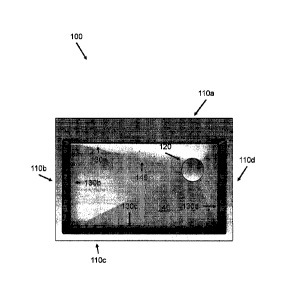
[0030] FIG. 1 is a top view of a sink with one basin in accordance with
embodiments of
the disclosure;
[0031] FIG. 2 is a diagram of the basin of FIG. 1 in accordance with
embodiments of the
disclosure;
[0032] FIG. 3A is a diagram of a ledge of the sink of FIG. 1 in
accordance with
embodiments of the disclosure;
[0033] FIG. 3B is a cross-sectional view of the ledge 300 of FIG. 3A in
accordance with
embodiments of the disclosure;
[0034] FIG. 4 is a perspective view of a sink with two basins and a
divider in accordance
with embodiments of the disclosure;
[0035] FIG. 5A is a diagram of the basin of FIG. 4 in accordance with
embodiments of the
disclosure;
6
Date Recue/Date Received 2023-09-20
[0036] FIG. 5B is a cross sectional view of a divider on the right and a
front view of the
divider on the left in accordance with embodiments of the disclosure;
[0037] FIG. 6 is a diagram of a basin including an inclined bottom
surface in accordance
with embodiments of the disclosure;
[0038] FIG. 7A is a diagram of a basin including a floating ledge in
accordance with
embodiments of the disclosure;
[0039] FIG. 7B is a cross-sectional view of the basin of FIG 7A, when
completed, in
accordance with embodiments of the disclosure;
[0040] FIG. 7C is an expanded view of "D" of FIG. 7A in accordance with
embodiments
of the disclosure;
[0041] FIG. 8 is a flow diagram showing a method of making a sink in
accordance with
embodiments of the disclosure; and
[0042] FIG. 9 is a block diagram for performing operations to make a
sink in accordance
with embodiments of the disclosure.
DETAILED DESCRIPTION
[0043] As disclosed, sinks may be configured to include one or more
basins. The sinks
may also be configured to include one or more floating ledges without
decreasing the total volume
of the sink. Further, the sinks may include one or more steps, ledges or
flanges, which increase the
volume of the sink. Furthermore, the thickness of a ledge, which is welded to
the one or more
basins, may be configured to be different from the thickness of the basin of
the sink. The list of
7
Date Recue/Date Received 2023-09-20
sinks as described in this disclosure provide examples and can include other
variants as readily
appreciated by a person of ordinary skill in the art.
100441 Like numerals in the present disclosure generally refer to the
same parts or elements
of the sinks. For example, 130a-130d of FIG. 1, 230a-230d of FIG. 2, 530a-530d
of FIG. 5, and
630a-630d of FIG. 6 refer to the same parts or elements for four vertical
sidewalls of the sinks.
When descriptions for the same parts for different sinks are duplicative or
redundant, such
descriptions may be omitted for the sink and refer to the corresponding
descriptions for sinks
previously described.
[0045] Some reference numerals are omitted from the figures because such
reference
numerals can be readily appreciated by a person having skill in the art even
with omission thereof.
For example, FIG. 4 does not include 430a-430d because a person of skill in
the art would readily
appreciate the four vertical sidewalls of the sink even with omission of such
reference numerals.
In this case, descriptions of the omitted reference numerals can be found in
sinks previously
described in FIGS. 1-3.
[0046] Referring to FIG. 1, a sink 100 includes four parts 110a-110d (as
a whole "110")
of a ledge, a drain 120 for draining liquids or foodstuffs, four vertical
walls or sides 130a-130d,
and a bottom surface 140. The four vertical sidewalls 130a-130d and the bottom
surface 140 form
a basin, which provides an inner space for performing operations, such as
washing.
[0047] The ledge 110 may be provided so that the sink 100 may sit on a
countertop of a
cabinet. The ledge, which is a combination of the four parts 110a-110d and is
referred to as deck
110, may be formed by any material known in the sink art, such as stainless
steel. The four vertical
8
Date Recue/Date Received 2023-09-20
sidewalls 130a-130d and the bottom surface 140 may be formed by the same
material, such as
stainless steel. As known in the art, steel is measured by gauge, with thinner
stainless steel having
a higher gauge number, and thicker stainless steel having a lower number. For
example, an 18
gauge (0.05 inches) sink is more durable and more expensive than a 22 gauge
(0.0312 inches)
stainless steel sink which are more susceptible to bowing, denting and dings.
Stainless steel made
of thin gauges is adequate for smaller sinks. However, larger sinks are more
efficient and
functional when they are thicker. A 20 gauge, which is 0.0375 inches, is a
better option with 18-
19 gauge sinks being a standard size and at the lower end of the price scale.
An even more costly
and better quality sink is a 16 gauge, and is 0.0625 inches (about 1.59
millimeters ("mm")) in
thickness, mostly used in commercial establishments.
100481 In the present disclosure, the thickness of the deck 110 may be
thicker than the
thickness of the material that forms the four vertical sidewalls 130a-130d and
the bottom surface
140. In an aspect, the material that forms the four vertical sidewalls 130a-
130d and the bottom
surface 140 may be 16-gauge stainless steel (about 1.59 mm) and the deck 110
may be at least 3
mm (about 0.12 inches) stainless steel. Thus, the deck 110 being about twice
as thick as the four
vertical sidewalls 130a-130d can provide more durability and stability than
simply a total 16-
gauge stainless steel sink. In an aspect, the material, which forms the deck
110, the four vertical
sidewalls 130a-130d, and the bottom surface 140, may be any metal or non-
metal, which can be
utilized and readily understood for sinks by a person having skill in the art.
[0049] In an aspect, the part 110a of the deck 110 may be wider than the
other three parts
110b-110d of the deck 110 and is configured to house the faucet, a filter, a
dispenser for soap or
9
=
Date Recue/Date Received 2023-09-20
lotion or other items known in the art and any accessories typically found
near a faucet. In another
aspect, the four parts 110a-110d may have the same thickness.
[0050] The deck 110 may be beveled at outer portions of the four parts
110a-110d. By
decreasing the thickness of the deck 110 toward the countertop of the cabinet,
the sink 100 may
appear to be integrated with the countertop. In other words, the transition
from the countertop to
the deck 110 may be smooth. In other words, when an item is swept into the
sink 100, the item is
not caught in or under the deck 110 of the sink 100. The shape of the beveled
parts may be linear
or curved.
[0051] The sink 100 further has four grooves 145 starting from the drain
120 to four
corners formed by the four vertical sidewalls 130a-130d and the bottom surface
140. The four
grooves 145 may lead water or fluid in the basin to the drain 120 to expedite
drainage. The four
grooves 145 may further provide for aesthetic features.
[0052] The location of the drain 120 may be determined based on needs of
customers. For
example, the drain 120 may be located in the center, top right, top left,
bottom right, or bottom left
of the bottom surface 140 of the basin.
[0053] Referring to FIG. 2, and a method of making a sink of the present
disclosure, a two-
dimensional pattern 200 for the basin of the sink 100 of FIG. 1 is drawn on a
material, which may
be stainless steel. The pattern 200 includes a drain 220, similar to drain
120, four rectangles 230a-
230d, similar to the four vertical sidewalls 130a-130d, and a bottom 240,
similar to the bottom
surface 140. Thus, the pattern 200 is a basin of the sink 100 after cutting,
folding, welding, and
smoothening out the sink.
Date Recue/Date Received 2023-09-20
[00541 The pattern 200 may be drawn on a sheet of stainless steel, of
which thickness may
be equal to or less than 16 gauge or about 1.6 mm. The pattern 200 has dotted
lines and solid lines.
The solid lines are to be cut, and the dotted lines are to be folded ninety
degrees toward the inside.
The pattern 200 also includes dash-dotted lines 245, which are to be pressed
to make the dash-
dotted lines 245 groove downward. Such grooves may facilitate water or any
liquid to the drain
220. Pressing may form a declining angle of about 3 to about 8 from the
normal plane or main
level of the base of the sink. Further, the pressing may cause the bottom of
the drain 220 to be
lower than the general bottom of the basin.
100551 The bottom surface of the basin may be downwardly inclined toward
the drain 220
while pressing the dash-dotted lines 245. With the grooves and the downward
inclination toward
the drain 220, the water or fluid contained in the sink 100 can be drained
efficiently.
[0056] For example, the outer boundaries, solid lines, of the four
rectangles 230a-230d are
cut and the inside boundaries, dotted lines, of the four rectangles 230a-230d
are folded ninety
degrees toward the inside or facing each other. The solid circular line 220 of
the bottom 240 is cut
so as to make an opening for drainage in the bottom 240.
10057] The pattern 200 also includes four corners, where adjacent two of
the four
rectangles 230a-230d meet. Area A where the rectangles 230b and 230c meet is
magnified to show
details of the corner of the pattern 200. As shown, the rectangles 230b and
230c do not
perpendicularly meet at the corner. Rather, a portion of the corner is cut
toward the inside by a
predetermined distance. After the four rectangle parts 230a-230d are folded to
make four vertical
11
Date Recue/Date Received 2023-09-24
sidewalls of the sink 100, each pair of adjoining edges of the four rectangles
230a-230d is welded
together and smoothened out.
[0058] The circular portion referenced by "A" shows an expanded view of
one of four
bottom corners, meaning that the other three bottom corners have the same
shape as shown in the
expanded view. The corner has a cut-out portion to be welded and smoothened
out. Thus, the
welded and smoothened cut-out corner 250 makes the corner round and smooth
without a sharp
corner or edge. The shape of the cut-out corner 250 may be in any shape, which
may turn out
= smooth and round when welded.
[0059] Further, the expanded view also includes dash-dotted lines 255
along the vertical
sidewalls and starting around the cut-out portion 250. The dash-dotted lines
255 are to be pressed
similar to the dash-dotted lines 245. When the dash-dotted lines 255 are
pressed and the dotted
lines are bent, two adjacent vertical lines of the vertical sidewalls 230b and
230c meet each other
and become smooth and rounded when welded together.
[0060] Furthermore, the folded lines of the four rectangles 230a-230d
may be also
smoothened out in a similar manner as the dash-dotted lines 255 are pressed
and welded together.
[0061] In another aspect, the welding may be performed by laser, light,
or any metal arc
welding means. Further, the welding is performed outside of the sink 100, such
that the welding
marks are not seen from the inside of the sink 100.
[0062] Next, the basin of the sink 100 needs to be welded with a deck to
complete the sink
100. FIG. 3A shows a deck 300 including four parts 310a-310d. These four parts
310a-310d may
be cut out from a sheet of stainless steel. The thickness of the stainless
steel of the deck 300 may
12
Date Recue/Date Received 2023-09-20
be thicker than the stainless steel for the basin. In an aspect, the thickness
of the deck 300 may be
3 mm while the thickness of the stainless steel for the pattern 200 may be 16
gauge or about 1.6
mm.
[0063] In an aspect, the end portions of the four parts 310a-310d may
have a 45 shape so
that, when the four parts 310a-310d are put together, the four parts 310a-310d
may form a deck.
[0064] The four parts 310a-310d may be welded together to form the deck
300 as the deck
110 of FIG. 1. The welding may be performed outside of the basin so that the
welding marks are
not seen from inside of the basin. The outer portions of the deck 300 may be
beveled so that the
thickness becomes shallow toward the end of the outer portion of the deck. For
example, FIG. 3B
shows a cross-sectional view of the deck 300 along the B-B direction of FIG.
3A. The slope from
the top surface of the deck 300 to the bottom surface of the deck 300 may be
linear as shown in
FIG. 313. The connection between the edge of the top surface and the edge of
the bottom surface
may be linear, concave, convex, or curved. In this way, when the sink 100 sits
on a countertop, the
outer edges of the deck 300 forms a smooth transition between the sink 100 and
the countertop.
[0065] The inside of the deck 300 may match the inside of the basin
formed from the
pattern 200 of FIG. 2. When welded to the basin of FIG. 2, the deck 300
appears protruding outside
from the top of the basin. Further, the deck 300 may sit on a countertop of a
cabinet. In an aspect,
the deck may be glued to the bottom surface of the countertop of the cabinet.
Due to the thickness
of the deck 300, which is greater than the thickness of the basin, the deck
300 may provide more
stability and durability in holding materials and liquid inside the basin.
Further, the thickness of
13
Date Recue/Date Received 2023-09-20
the deck 300 may prevent waviness after installation and damages during
shipping, thereby making
the deck 300 more durable.
10066] FIG. 4 illustrates a sink 400 in accordance with embodiments of
the present
disclosure. The sink 400 includes every element of the sink 100 of FIG. 1 and
a divider 460, such
that sink 400 has two basins. The sink 400 may have one drain in each basin.
Descriptions of
similar or same elements of the sink 400 as the sink 100 of FIG. 1 may be
found in FIGS. 1-3
above.
[0067] The height of the divider 460 may be less than the height of the
basin of the sink
400 so that movements of solid or liquid between two basins are easier. In an
aspect, the thickness
of the divider 460 may be from about 2.5 mm to about 5 mm, with embodiments of
about 4 mm
or 0.16 inches. In an aspect, the material of the divider 460 is the same as
the basin of the sink 400.
Even though the thickness of the divider 460 is greater than the thickness of
the basin or the deck
of the sink 400, 0.16 inches is much smaller than the conventional dividers in
the sink art. Thus,
the divider 460 is very thin compared to the volume of the basin and may not
substantially reduce
the volume of the inner space of the basin. The divider 460 may be positioned
in the middle, more
towards the right or more towards the left in a width direction.
100681 FIG. 5A illustrates a pattern 500 for the basin of the sink 400
of FIG. 4 and FIG.
5B illustrates a divider 560 of the sink 400. The pattern 500 includes four
rectangles 530a-530d,
which become the four vertical sidewalls of the sink 400. Detailed
descriptions for the four
rectangles 530a-530d can be found in the description of the four rectangles
230a-230d of FIG. 2
above.
14
Date Recue/Date Received 2023-09-20
[0069] The pattern 500 further includes two drains 520a and 520b, of
which descriptions
can also be found when discussing the drain 220 of FIG. 2. In an aspect, the
drain 520a on the right
side may be positioned the same distance from the dotted edge of the rectangle
530a as the drain
520b from the dotted edge of the rectangle 350a. The position of the drain
520a may be determined
independently from the position of the drain 520b. The size of the drains 520a
and 520b may be
determined based on the area of the corresponding basin.
[0070] Further, the pattern 500 also includes dash-dotted lines, which
are to be pressed to
make the dash-dotted lines groove downward to the drains 520a and 520b. Such
grooves may be
configured to facilitate water or any liquid to the drains 520a and 520b.
[0071] The bottom surface may be downwardly inclined toward the opening
while pressing
the dash-dotted lines. With the grooves and the downward inclination toward
the drains 520a and
520b, the water or fluid contained in the sink can be drained efficiently.
[0072] Two bottoms 540a and 540b become bottom surfaces of two basins
when the
pattern 500 is cut and folded according to the solid, dotted, and dash-dotted
lines thereon.
[0073] The pattern 500 further includes a strip 555 for a divider. The
strip 555 may have a
width W and a length 2H + L. When solid lines of the strip 555 are cut, the
inside is cut off and a
strip-like opening is formed in the pattern 500. In particular, the opening is
formed on the part of
two vertical sidewalls formed in the rectangles 530a and 530c by H, and is
formed between the
bottoms 540a and 540b by L. In an aspect, the short edges of the strip 555 may
be rounded. When
the dash-dotted lines are pressed, the drains 520a and 520b may be lowered so
that water or liquid
Date Recue/Date Received 2023-09-20
can be led to the drains 520a and 520b. As such, the strip 555 may be
distanced from both drains
520a and 520b so that the strip 555 and the divider can be welded with ease.
[0074] FIG. 5B illustrates a cross-sectional view of a divider 560 on the
right and a front
view of the divider 560 on the left. In an aspect, the material of the divider
560 may be the same
as the material on which the pattern 500 is drawn. For example, the material
is 16-gauge stainless
steel, which is about 1.6 mm thick. In another aspect, the width of the strip
555 may be 4.0 mm,
which is greater than twice the thickness of the 16-gauge stainless steel.
[0075] The width W of the divider 560 may be equal to the width W of the
strip 555, and
the height H of the divider 560 may be equal to H of the strip 555. The length
L of the divider 560
may be equal to L of the strip 555. The length side of the divider 560 in the
bottom may be welded
into the part of the opening formed between the bottoms 540a and 540b. Both
height sides of the
divider 560 may be welded into the part of the opening formed in the vertical
sidewalls, which are
formed in the rectangles 530a and 530c.
[0076] In an aspect, the top part of the divider 560 may be rounded. As
such, the short
edges of the strip 555 may also be rounded so that the rounded part may fit
into the rounded parts
of the strip 555. In another aspect, the shape of the top part of the divider
560 may be rectangular,
elliptical, or any other shape, which is to be matched with the shape of the
short edges of the strip
555.
[0077] In aspects, the width of the divider 560 may be less than or equal
to 4.0 mm. When
compared with dividers of conventional sinks, the width of the divider 560 is
substantially smaller
than those of the conventional sinks. Thus, the divider 560 takes up minimal
amount of volume of
16
Date Recue/Date Received 2023-09-20
the basin. Further, the welding is performed outside of the basin and welding
marks are
smoothened out. Thus, there are no welding marks seen from inside of the
basin.
[0078] In aspects, the top part of the divider 560 may be thinner than
the bottom part of
the divider 560. As such, the divider 560 may be inserted into an opening of
the strip 555 from the
outside of the basin. Since the top part of the divider 560 is thinner than
the width W of the strip
555, the divider 560 may be easily inserted into the opening of the strip 555.
Further, it becomes
easy to fit the bottom of the divider 560 to the bottom of the strip 555.
[0079] Further, the deck such as the deck 110 of FIG. 1 may be welded
with the basin
formed by the pattern 500. Welding may be also performed outside of the basin
and welding marks
and lines may be smoothened out. Further, the welding may be performed inside
of the basin and
the welding marks and lines may be smoothened out by a polishing tool, which
may include a
pencil-sized diamond polishing tool and any polishing tools suitable for
removing welding marks
and lines. As such, the welding marks between the deck and the basin cannot be
seen from the
inside and outside of the basin.
[0080] FIG. 6 illustrates a pattern 600 for a basin, which has an
inclined bottom surface
640a, in accordance with embodiments of the disclosure. The pattern 600
includes two
parallelograms 630a and 630c. The parallelograms 630a and 630c include two
parallel vertical
sidewalls, one is longer than the other. The length of the longer side of the
parallelograms 630a
and 630c is equal to the length of the top and bottom of the rectangle 630d.
The length of the
shorter side of the parallelograms 630a and 630c is equal to the length of the
top and bottom of the
rectangle 630b.
17
Date Recue/Date Received 2023-09-20
[0081] The drain 620 may be positioned toward the rectangle 630d rather
than 630b so that
the drain 620 is positioned toward the lower part of the inclination. Each
edge of the bottom surface
640 may also have a cut-out corner such as the cut-out corner 250 of FIG. 2 so
that each corner of
the basin, when welded, can be made rounded. Further, the deck may be welded
to the top of the
basin formed by the pattern 600.
[0082] FIG. 7A illustrates a pattern 700 of a basin, which includes a
floating deck 790 and
FIG. 7B shows a cross-sectional view of the basin of FIG. 7A, when completed,
along the direction
C-C in accordance with embodiments of the disclosure. The floating deck 790
increases the
volume of the basin, while the deck does not change the volume of the basin.
The pattern 700
includes two rectangles 730a and 730c, which face each other. Each of the two
rectangles 730a
and 730c includes dotted lines 770 and dash-dot-dotted lines 780. The dotted
lines 770 are to be
folded in the same direction, i.e., inside the basin, as the other dotted
lines in the pattern 700. The
dash-dot-dotted lines 780 are to be folded toward the outside of the basin. In
particular, dotted lines
770 are to be folded about 90 degrees toward the inside of the basin, while
the dash-dot-dotted
lines 780 are to be folded about 90 degrees toward the outside of the basin.
Thus, when folded
properly, the part between the dotted lines 770 and the dash-dot-dotted line
780 forms the floating
deck 790, which is substantially parallel with the bottom surface of the
basin. As such, the floating
deck 790 is not welded to the basin. The width of the floating deck 790 may be
less than or equal
to about 0.59 inches.
[0083] The floating deck 790 neither decreases nor increases the volume
of the basin. In
an aspect, the pattern 700 may include two or more pairs of the dotted lines
770 and the dash-dot-
18
Date Recue/Date Received 2023-09-20
dotted lines 780 so that the basin has two or more floating decks. The
floating deck formed on the
both vertical sidewalls 730a and 730c may be used to put a working board or
accessory thereon,
so as to put items (e.g., dishes, kitchen utensils, etc.) while washing or for
handling, storing or
cutting food.
[0084] Further, the shapes of two vertical sidewalls 730b and 730d are
adjusted according
to the floating deck formed by the dotted lines 770 and the dash-dot-dotted
lines 780 in the vertical
sidewalls 730a and 730c, and are matingly-welded to the vertical sidewalls
730b and 730d. The
top surface of the basin may be welded to a deck such as the deck 110 of FIG.
1.
[0085] In an aspect, the floating deck may be formed on the short sides
of the basin or on
all vertical sidewalls of the basin. In another aspect, whenthere are two
floating decks in the basin,
one floating deck may be formed along the long side and the other floating
deck may be formed
along the short side. A cutting board or a rolling mat may be placed on the
first floating deck
formed along the long side and another accessory may be placed on the second
floating deck
formed along the short side. In still another aspect, two floating deck may be
formed along the
same direction, the long or short side of the basin.
[0086] In case when the floating decks are formed on the two facing short
vertical
sidewalls 730b and 730d of the basin, an accessory such as a cutting board may
sit on the floating
decks. As shown in FIG.7B, the width of the floating deck 790 is WL and the
width of the lower
portion of the basin 700 is W. As such, an accessory can sit on the two
floating decks 790 when
the width of the accessory is greater than WB+WL and less than or equal to
Wa+2WL. Based on
the length of the basin 700, two or more accessories may sit on the floating
deck 790 at the same
19
Date Recue/Date Received 2023-09-20
time, when the sum of the lengths of two or more accessories is less than or
equal to the length of
the basin 700.
100871 In case when two or more levels of floating decks are vertically
formed on the same
two facing sides of the basin 700, accessories having different dimensions may
sit on different
levels of the floating decks. The accessories are dimensioned and configured
to sit on the
corresponding floating deck.
100881 FIG. 7C is the expanded view of "D" in FIG. 7A in accordance with
embodiments
of the present disclosure. Two vertical sidewalls 730b and 730c have two sharp
protrusions 745a
and 745b from the top thereof. When folded and welded together, the two sharp
protrusions 745a
and 745b form a deck of the sink 700. In an aspect, the angle 01 of the sharp
protrusion 745a and
the angle 02 of the sharp protrusion 745b may be 90 so that the sharp
protrusions 745a and 745b
fit to each other when welded together. In another aspect, 01 and 02 do not
have to be a right angle
and thus, the sum of 01 and 02 may be 180 . Therefore, the sink made with this
design may not
require a deck, as shown in FIGS. 3A and 3B, to be welded thereto. Further,
the pattern having
these two sharp protrusions 745a and 745b may be applied to any designs shown
in FIGS. 2A-7A.
[0089] Each embodiment as shown in FIGS. 1-7C is not limited thereto but
can be
combined with each other to form a sink as appreciated by a person having
ordinary skill in the
art. Further, other types of sink may be also encompassed by this disclosure
without departing from
the spirit of this disclosure.
[0090] FIG. 8 illustrates a method 800 for manufacturing a sink in
accordance with
embodiments of the present disclosure. The method 800 begins by drawing a
pattern for a basin of
Date Recue/Date Received 2023-09-20
a sink on a metal sheet in step 810. The pattern may include an opening for a
drain and a rectangular
strip for a divider. In an aspect, the rectangular strip for the divider may
not be included in the
pattern. The thickness of the metal sheet may be less than or equal to 16-
gauge or about 1.6 mm.
The pattern may include solid lines, which are to be cut, and dotted lines,
which are to be folded
90 degrees toward an inside of the basin. Further, the pattern may include
dash-dotted lines, which
are to be pressed to make the dash-dotted lines grooves downward. Furthermore,
the pattern may
include dash-dot-dotted lines, which are to be folded 180 degrees toward an
outside of the basin.
[0091] In step 820, the solid lines are cut. An opening for a drain is
also in solid lines. After
cutting the solid lines on the metal sheet, the metal sheet becomes a skeleton
for a basin of the
sink. The cutting may be done by laser, high energy light, water, or any other
means to cut the
metal sheet.
[0092] In step 830, the dotted lines of the pattern are folded to form
four vertical sidewalls
of the basin. The dash-dotted lines are pressed so as to make a water way to
the drainage in the
bottom surface of the basin. Pressing may create a declining angle of from
about 30 to about 8
from the main level of the base of the sink so that water can be drained
toward the drainage. In a
case when the pattern includes dash-dot-dotted lines, the dash-dot-dotted
lines are folded by 90
degrees toward the outside of the basin so as to form a floating deck, as
shown in FIGS. 7A and
7B.
[0093] The adjacent edges of the four v.ertical sidewalls are welded
together in step 840.
The welding may be performed from the outside of the basin so that the welding
marks are not
seen from the inside of the basin.
21
Date Recue/Date Received 2023-09-20
[00941 The main basin may be divided into two or more smaller basins. In
this case, each
basin is separated by a divider. In this case, the pattern may also include a
strip of solid lines, which
are to be cut, inside of the basin. Step 850 may be performed for a sink
having a divider. When
the solid lines are cut in step 820, the strip is also cut to leave a long
strip of an opening.
100951 The divider may be cut out from the same metal sheet as the basin
and folded in
half. Thus, the width of the divider may be slightly greater than twice the
thickness of the metal
sheet. In an aspect, the metal sheet may be stainless steel, of which the
thickness may be less than
or equal to 16-gauge, and the width of the divider may be less than or equal
to about 4.0 mm. The
top of the divider may be thinner than the bottom of the divider. Thus, the
bottom of the divider
may easily fit to the opening of the strip by inserting the top of the divider
from outside of the
basin and from the bottom into the opening of the strip. The divider may then
be welded into the
opening. Welding may also be performed from the outside of the basin.
100961 In step 860, four rectangular pieces of another metal sheet
different from that for
the basin are cut and welded together to form a rectangular rim, configured as
a deck of the sink.
The inside of the rectangular rim may fit to the top rectangular opening of
the basin. The metal
sheet for the deck may be thicker than the metal sheet for the basin. In an
aspect, the thickness of
the deck may be greater than or equal to 3.0 mm, and the thickness of the
metal sheet for the basin
may be 16 gauge, about 1.6 mm. By making a deck thicker than the basin, the
sink is configured
to sit tightly on a countertop of a kitchen cabinet.
[00971 In step 870, the inside of the rectangular rim and the top edges
of the basin are
welded together. The welding may be performed from the outside of the basin.
In an aspect, the
22
Date Recue/Date Received 2023-09-20
deck may be beveled at the outer part of the rectangular rim. When the deck
welded with the basin
is located on the countertop of the kitchen cabinet, the deck touches the top
surface of the
countertop. The beveled edge provides a smooth transition from the top surface
of the countertop
to the deck of the sink.
[0098] In step 880, the welded parts or edges are smoothened out. For
example, the welded
parts of the four vertical sidewalls and welded parts between the deck and the
basin are smoothened
out outside of the sink. In an aspect, smoothening the welded parts may be
performed inside of the
basin to remove any welding marks or any other visible marks. The method 800
ends after the
smoothening process in step 880.
[0099] FIG. 9 is a block diagram for a computing device 900, which is
configured to
perform operations to make a sink in accordance with embodiments of the
disclosure. The
computing device 900 may be connected to one or more external devices and
control the external
devices to cut, fold, and weld metal sheets so as to make a sink by performing
steps of the method
800. The computing device 900 may include, by way of non-limiting examples,
server computers,
desktop computers, laptop computers, notebook computers, sub-notebook
computers, netbook
computers, netpad computers, set-top computers, handheld computers, Internet
appliances, mobile
smartphones, tablet computers, personal digital assistants, video game
consoles, embedded
computers, and autonomous vehicles. Those of skill in the art will recognize
that many
smartphones are suitable for use in the system described herein. Suitable
tablet computers include
those with booklet, slate, and convertible configurations, known to those of
skill in the art.
23
Date Recue/Date Received 2023-09-20
[0100] In some embodiments, the computing device 900 includes an
operating system
configured to perform executable instructions. The operating system is, for
example, software,
including programs and data, which manages the device's hardware and provides
services for
execution of applications. Those of skill in the art will recognize that
suitable server operating
systems include, by way of non-limiting examples, FreeBSD, OpenBSD, NetBSDO,
Linux,
Apple Mac OS X Server , Oracle Solaris , Windows Serversi, and Nove1ltI
NetWare .
Those of skill in the art will recognize that suitable personal computer
operating systems include,
by way of non-limiting examples, Microsoft4 Windows41), Apple'. Mac OS X ,
UNIX , and
UNIX- like operating systems such as GNU/Linux. In some embodiments, the
operating system
is provided by cloud computing. Those of skill in the art will also recognize
that suitable mobile
smart phone operating systems include, by way of non-limiting examples, Nokia
Symbian OS,
Apple i0S , Research In MotionO BlackBerry OS , Google Android , Microsoft4
Windows Phone OS, Microsoft'. Windows Mobile OS, Linux , and Palm WebOSO.
101011 In some embodiments, the computing device 900 may include a
storage 910. The
storage 910 is one or more physical apparatus used to store data or programs
on a temporary or
permanent basis. In some embodiments, the storage 910 may be volatile memory
and requires
power to maintain stored information. In some embodiments, the storage 910 may
be non-volatile
memory and retains stored information when the computing device 900 is not
powered. In some
embodiments, the non-volatile memory includes flash memory. In some
embodiments, the non-
volatile memory includes dynamic random-access memory (DRAM). In some
embodiments, the
non-volatile memory includes ferroelectric random-access memory (FRAM). In
some
24
Date Recue/Date Received 2023-09-20
embodiments, the non-volatile memory includes phase-change random access
memory (PRAM).
In some embodiments, the storage 910 includes, by way of non-limiting
examples, CD-ROMs,
DVDs, flash memory devices, magnetic disk drives, magnetic tapes drives,
optical disk drives, and
cloud computing-based storage. In some embodiments, the storage 910 may be a
combination of
devices such as those disclosed herein.
[0102] The computing device 900 further includes a processor 930, an
extension 940, a
display 990, an input device 960, and a network card 970. The processor 930 is
a brain to the
computing device 900. The processor 930 executes instructions which implement
tasks or
functions of programs. When a user executes a program, the processor 930 reads
the program
stored in the storage 910, loads the program on the RAM, and executes
instructions prescribed by
the program.
[0103] The processor 930 may include a microprocessor, central processing
unit (CPU),
application specific integrated circuit (ASIC), arithmetic coprocessor,
graphic processor, or image
processor, each of which is electronic circuitry within a computer that
carries out instructions of a
computer program by performing the basic arithmetic, logical, control and
input/output (I/O)
operations specified by the instructions.
[01041 In embodiments, the extension 940 may include several ports, such
as one or more
universal serial buses (USBs), IEEE 1394 ports, parallel ports, and/or
expansion slots such as
peripheral component interconnect (PCI) and PCI express (PCIe). The extension
940 is not limited
to the list but may include other slots or ports that can be used for
appropriate purposes. The
extension 940 may be used to install hardware or add additional
functionalities to a computer that
Date Recue/Date Received 2023-09-20
may facilitate the purposes of the computer. For example, a USB port can be
used for adding
additional storage to the computer and/or an IEEE 1394 may be used for
receiving moving/still
image data.
[0105] In some embodiments, the display 990 may be a cathode ray tube
(CRT), a liquid
crystal display (LCD), or light emitting diode (LED). In some embodiments, the
display 990 may
be a thin film transistor liquid crystal display (TFT-LCD). In some
embodiments, the display 990
may be an organic light emitting diode (OLED) display. In various some
embodiments, the OLED
display is a passive-matrix OLED (PMOLED) or active-matrix OLED (AMOLED)
display. In
some embodiments, the display 990 may be a plasma display. In some
embodiments, the display
990 may be a video projector. In some embodiments, the display may be
interactive (e.g., having
a touch screen or a sensor such as a camera, a 3D sensor, a LiDAR, a radar,
etc.) that can detect
user interactions/gestures/responses and the like.
[0106] In still some embodiments, the display 990 is a combination of
devices such as
those disclosed herein.
[0107] A user may input and/or modify data via the input device 960 that
may include a
keyboard, a mouse, or any other device with which the user may input data. The
display 990
displays data on a screen of the display 990. The display 990 may be a touch
screen so that the
display 990 can be used as an input device.
[0108] The network card 970 is used to communicate with other computing
devices,
wirelessly or via a wired connection. Through the network card 970, the
autonomous vehicle may
receive, modify, and/or update data from and to a managing server.
26
Date Recue/Date Received 2023-09-20
[0109] Any of the herein described methods, programs, algorithms or codes
may be
converted to, or expressed in, a programming language or computer program. The
terms
"programming language" and "computer program," as used herein, each include
any language
used to specify instructions to a computer, and include (but is not limited
to) the following
languages and their derivatives: Assembler, Basic, Batch files, BCPL, C, C+,
C++, C#, Delphi,
Fortran, Java, JavaScript, machine code, operating system command languages,
Pascal, Pen, PL1,
python, scripting languages, Visual Basic, meta-languages which themselves
specify programs,
and all first, second, third, fourth, fifth, or further generation computer
languages. Also included
are database and other data schemas, and any other meta-languages. No
distinction is made
between languages which are interpreted, compiled, or use both compiled and
interpreted
approaches. No distinction is made between compiled and source versions of a
program. Thus,
reference to a program, where the programming language could exist in more
than one state (such
as source, compiled, object, or linked) is a reference to any and all such
states. Reference to a
program may encompass the actual instructions and/or the intent of those
instructions.
101101 It should be understood that the foregoing description is only
illustrative of the
present disclosure. Various alternatives and modifications can be devised by
those skilled in the
art without departing from the disclosure. Accordingly, the present disclosure
is intended to
embrace all such alternatives, modifications and variances. The embodiments
described with
reference to the attached drawing figures are presented only to demonstrate
certain examples of
the disclosure. Other elements, steps, methods, and techniques that are
insubstantially different
27
Date Recue/Date Received 2023-09-20
from those described above and/or in the appended claims are also intended to
be within the scope
of the disclosure.
28
Date Recue/Date Received 2023-09-20