Note: Descriptions are shown in the official language in which they were submitted.
ONE-HAND FOLDING STROLLER
PRIORITY CLAIM AND CROSS-REFERENCE TO RELATED APPLICATIONS
[0001] The present application claims priority and benefit of U.S.
Provisional Patent
App. No. 63/409,337 filed September 23, 2022, titled ONE-HAND FOLDING
STROLLER,
entire contents of which are incorporated by reference herein and relied upon.
TECHNICAL FIELD
[0002] The present invention generally relates to strollers, and more
specifically to
foldable strollers.
BACKGROUND
[0003] Strollers are wheeled devices used to transport passengers, which
are often
children. The seating mechanisms in strollers can vary. Similarly, passenger
capacity and
seat configuration can vary between strollers.
SUMMARY
[0004] Systems and methods for a stroller with a one-hand collapsing
mechanism in
accordance with embodiments of the inventions are disclosed. In a first aspect
of the
present disclosure, a folding stroller includes a collapsible frame, at least
one wheel in a
front part of the collapsible frame, at least one wheel in a rear part of the
collapsible frame,
at least one folding hinge coupled to the collapsible frame, a seating area
having a seat
portion and a back portion, and a release handle in the seat portion of the
seating area,
the release handle configured to be actuated with a one hand action, wherein
the release
handle is coupled to the at least one folding hinge, wherein the release
handle is acces-
sible through the seating area, and wherein actuating the handle causes the
frame to
transform from a deployed position to a collapsed position.
[0005] In a second aspect of the present disclosure, the rear wheels are
located a first
distance from the frame when the frame is in a deployed position and the rear
wheels are
located a second distance from the frame in the collapsed position, where the
second
distance is less than the first distance.
1
8765293
Date Recue/Date Received 2023-09-19
[0006] In a third aspect of the present disclosure, the seat portion of the
seating area
is coupled to the release handle.
[0007] In a fourth aspect of the present disclosure, the release handle
engages with
the seating portion to lock the seating area in place.
[0008] In a fifth aspect of the present disclosure, the collapsible frame
comprises at
least one folding hinge.
[0009] In a sixth aspect of the present disclosure, the at least one
folding hinge com-
prises a mating member and a hinge plate.
[0010] In a seventh aspect of the present disclosure, including a slide
lock that slidably
couples to the release handle.
[0011] In an eighth aspect of the present disclosure, the slide lock has a
locked con-
figuration where the slide lock engages with the release handle to prevent
release handle
actuation and the slide lock has an unlocked configuration where the slide
lock does not
engage with the release handle and does not prevent release handle actuation.
[0012] In a ninth aspect of the present disclosure, the slide lock is
toggled between
the locked configuration and the unlocked configuration by sliding the slide
lock from one
side to another side.
[0013] In a tenth aspect of the present disclosure, including a handle
spring that cou-
ples to the release handle such that tension in the handle spring orients the
release han-
dle in a first position.
[0014] In an eleventh aspect of the present disclosure, the release handle
is actuated
by engaging the release handle at the first position to overcome the tension
in the handle
spring such that the release handle moves to a second position.
[0015] In a twelfth aspect of the present disclosure, a folding stroller
release handle
assembly including a release handle coupled to a stroller seat frame, a handle
spring
coupled to the stroller seat frame and the release handle, and a handle lock.
Actuating
the release handle causes the stroller seat frame to transform from a deployed
position
to a collapsed position.
[0016] In a thirteenth aspect of the present disclosure, the release handle
has a front
portion and a rear portion.
2
8765293
Date Recue/Date Received 2023-09-19
[0017] In a fourteenth aspect of the present disclosure, the front portion
of the release
handle can be accessed through an aperture in a seat bottom that is coupled to
the stroller
seat frame.
[0018] In a fifteenth aspect of the present disclosure, the back portion of
the release
handle couples to the stroller seat frame so as to allow the release handle to
move about
a seat bottom that is coupled to the stroller seat frame.
[0019] In a sixteenth aspect of the present disclosure, tension from handle
spring ori-
ents the release handle in a rear-most position relative to the seat bottom.
When the
release handle is in the rear-most position relative to the seat bottom a set
of handle
engagement members in the release handle engage with the stroller seat frame
so as to
prevent the release handle from moving about the seat bottom.
[0020] In a seventeenth aspect of the present disclosure, the release
handle is actu-
ated by engaging the release handle at the rear-most position relative to the
seat bottom
so as to overcome the tension in the handle spring such that the release
handle moves
to a front-most position relative to the seat bottom and concurrently the set
of handle
engagement members in the release handle disengage from the stroller seat
frame such
that the release handle can move about the seat bottom.
[0021] In an eighteenth aspect of the present disclosure, the handle lock
is a slide lock
that has a locked configuration where the slide lock engages with the release
handle to
prevent release handle actuation and the slide lock has an unlocked
configuration where
the slide lock does not engage with the release handle and does not prevent
release
handle actuation.
[0022] In a nineteenth aspect of the present disclosure, sliding the slide
lock to a
locked configuration prevents the release handle actuation.
[0023] In a twentieth aspect of the present disclosure, a method for
folding a foldable
stroller that includes a collapsible frame, at least one wheel in a front part
of the collapsible
frame, at least one wheel in a rear part of the collapsible frame, at least
one folding hinge
coupled to the collapsible frame, a seating area having a seat portion and a
back portion,
and a release handle in the seat portion of the seating area. The method
includes actu-
ating the release handle and pivoting the release handle about the collapsible
frame such
that the collapsible frame transforms from a deployed position to a collapsed
position.
3
8765293
Date Recue/Date Received 2023-09-19
[0024] Other objects, advantages and novel features, and further scope of
applicability
of the present invention will be set forth in part in the detailed description
to follow, and in
part will become apparent to those skilled in the art upon examination of the
following, or
may be learned by practice of the invention. The objects and advantages of the
invention
may be realized and attained by means of the instrumentalities and
combinations partic-
ularly pointed out in the claims.
BRIEF DESCRIPTION OF THE DRAWINGS
[0025] The description will be more fully understood with reference to the
following
figures, which are presented as exemplary embodiments of the invention and
should not
be construed as a complete recitation of the scope of the invention, wherein:
[0026] FIGS. 1A-C are illustrations of a one-hand folding stroller in
accordance with
embodiment of the invention;
[0027] FIGS. 2A-B are illustrations of a foldable seat assembly in
accordance with
embodiments of the invention;
[0028] FIGS. 3A-C are illustrations of release handle assemblies in
accordance with
embodiments of the invention;
[0029] FIGS. 4A-B are illustrations of a hinge assembly in accordance with
embodi-
ments of the invention;
[0030] FIGS. 5A-B are illustrations of a one-hand folding action for a one-
hand folding
stroller in accordance with embodiments of the invention;
[0031] FIG. 6 is an illustration of the operation of a release handle for a
one-hand
folding stroller in accordance with embodiments of the invention; and
[0032] FIG. 7 is an illustration of the operation of a release handle for a
one-hand
folding stroller in accordance with embodiments of the invention.
DETAILED DESCRIPTION
[0033] Turning now to the drawings, systems and methods for a stroller with
a one-
hand collapsing mechanism in accordance with embodiments of the inventions are
dis-
closed. Strollers are wheeled, user-pushed vehicles generally used to
transport children
in a seated position. The number of wheels and seat configurations can vary
between
strollers. For example, some strollers can have rear-facing seats, while
others can have
4
8765293
Date Recue/Date Received 2023-09-19
forward-facing seats. Similarly, some strollers have four wheels, while other
strollers have
three wheels. As another variation, some strollers have non-collapsible
frames, while
other strollers have collapsible frames. For folding stroller frames, users
often have to
engage with multiple locking parts such as clips, handles, straps and hinges,
among other
parts, in order to fold the stroller frame for ease of storage. As such,
folding the stroller
often requires both user hands to engage with the various locking parts.
Moreover, folding
the stroller often takes multiple steps, such as first unlocking the seat
portion and then
unlocking the stroller frame.
[0034] Strollers in accordance with embodiments of the invention include a
one-hand
folding mechanism. The frame collapsing mechanism includes a release handle
located
on the stroller seat. The release handle couples with one or more frame hinge
mecha-
nisms on the stroller frame. When the user engages the release handle, for
example by
pushing or sliding the release handle, the user unlocks the seat folding
mechanism and
the frame hinge mechanism simultaneously. As such, the user can transition the
stroller
from deployed position to collapsed position with the use of the release
handle. In a vari-
ety of embodiments, the rear wheels retract towards the stroller frame when
the stroller
transitions from deployed position to the collapsed position.
[0035] In this way, one-hand folding strollers in accordance with
embodiments of the
invention are significant improvements over existing designs. For example, the
one-hand
folding mechanism allows users to fold the stroller frame using a singular
step with the
use of one hand. Existing designs typically use multiple steps, such as first
unlocking the
seat and/or engaging multiple folding hinges with the use of both hands. Also,
one-hand
folding strollers, when in the collapsed position, are more compact than the
typical de-
signs, thereby improving the ease of transporting and/or storing the one-hand
folding
stroller.
[0036] Systems and methods for strollers with a one-hand collapsing
mechanism in
accordance with embodiments of the invention are described in more detail
below.
One-Hand Folding Stroller
[0037] FIGS. 1A-C are renderings of a one-hand folding stroller in
accordance with
embodiments of the invention. Turning now to FIG. 1A, a perspective view of a
stroller is
8765293
Date Recue/Date Received 2023-09-19
shown. The stroller 100 includes a collapsible frame 120 with at least one
front wheel 104
coupled to a front portion of the collapsible frame 120 and at least one
removable rear
wheel 105 coupled to a rear portion of the collapsible frame 120. In a variety
of embodi-
ments, the front wheel(s) 104 and/or rear wheel(s) 105 are removably coupled
to the
stroller 100. The collapsible frame 120 includes left and right upper members
103, a lower
member 102, left and right rear members 110, left and right top rods 111, and
left and
right bottom rods 112. In the front of the collapsible frame 120, the left
upper member 103
couples with the top left side of the lower member 102 via a left folding
hinge 109 and the
right upper member 103 couples with the top right side of the lower member 102
via a
right folding hinge 109. The bottom of the lower member 102 couples with the
removable
front wheel(s) 104. The top of the left rear member 110 couples to the left
upper portion
103 at a left upper fold point 115 and the top of the right rear member 110
couples to the
right upper portion 103 at a right upper fold point 115. The bottom of the
left and right rear
members 110 each couple to one or more rear wheel assembly 105.
[0038] The left top rod 111 couples with the left hinge 109 at the left
hinge point 118
on a first end, and the left rear member 110 at the left back fold point 116
on a second
end. The right top rod 111 couples to the right side of collapsible frame 120
in the same
way. Additionally, the left bottom rod 112 couples with the left side of the
lower member
102 at the left lower fold point 119 on a first end, and the left rear member
110 at the left
support fold point 117 on a second end. The right bottom rod 112 couples to
the right side
of collapsible frame 120 in a similar manner.
[0039] The stroller 100 has a seating area that includes a seat bottom 106
and a seat
back 107 located between the left and right sides of the collapsible frame
120. A release
handle 108 is coupled to the seat bottom 106.
[0040] Turning now to FIG. 1B, a side view of the stroller 100 is shown. As
shown in
FIG. 1B, the stroller 100 includes a seat frame 113 that couples to the lower
member 102
at the lower fold point 119. Additionally, the seat bottom 106 couples to the
seat frame
113 via screws or fasteners, for example.
[0041] Turning now to FIG. 1C, a rear view of stroller 100 is shown. As
shown in FIG.
1C, a support crossbar 114 is located between the left and right side of the
stroller 100
below the rear of the seat frame 113. In several embodiments, the seat frame
113 rests
6
8765293
Date Recue/Date Received 2023-09-19
on the support crossbar 114. In a variety of embodiments, left and right
removable rear
wheels 105 each couple with a respective left and right wheel retraction
assembly 101.
The left and right wheel retraction assemblies 101 couple with the left and
right rear mem-
bers 110, respectively. Each wheel retraction assembly 101 includes one or
more axles
pivoting with respect to a corresponding rear member and a piston moving with
respect
to the corresponding rear member as the stroller 100 converts between a
deployed posi-
tion and a collapsed position.
[0042] It should be noted that the components of stroller 100 can be made
from a
variety of materials including steel, aluminum, plastics, carbon fiber,
fiberglass, and/or
any other material of a suitable weight, strength, and durability. A variety
of materials
and/or combinations of materials can be utilized as appropriate to the
requirements of
specific applications of embodiments of the invention.
[0043] FIGS. 1A-C are illustrative embodiments of a folding stroller and
many config-
urations are appropriate. For example, a number of folding strollers,
including those that
use alternative elements to couple the front and rear of the stroller and
those without
retractable wheels, can be utilized as appropriate to the requirements of
specific applica-
tions of embodiments of the invention.
Foldable Seat Assemblies
[0044] FIGS. 2A-B are renderings of a foldable seat assembly in accordance
with em-
bodiments of the invention. Turning now to FIG. 2A, perspective view of a
foldable seat
assembly is shown. The seat assembly 200 includes a seat back 201 and a seat
bottom
202. The seat back 201 couples with the seat bottom 202 via screws, fasteners,
hinges,
or the like, so as to allow the seat back 201 and seat bottom 202 to remain
coupled while
moving about one another. A release handle 205 couples with the back of the
seat bottom
202. In a variety of embodiments, the release handle 205 fits in a cutout on
the seat
bottom 202. In many embodiments, the release handle 205 can be actuated by the
user
by applying force in a direction such that the release handle 205 is pulled
from the back
of the seat bottom 202 towards the front of the bottom seat 202. In addition,
the seat
bottom 202 couples with a seat frame 203. The front left side of the seat
frame 203 cou-
ples with a first end of a left bottom rod 206 via a lower fold point 207.
Similarly, the front
7
8765293
Date Recue/Date Received 2023-09-19
right side of the seat frame 203 couples with a first end of a right bottom
rod 206 via a
lower fold point 207. Moreover, a support crossbar 204 couples with the left
and right
bottom rods 206 via screws or fasteners, for example, such that a first end of
the support
crossbar 204 couples with one bottom rod 206 and a second end of the support
crossbar
204 connects with a second bottom rod 206. The support crossbar 204 couples
with the
left and right bottom rods 206 such that it aligns with the rear of the seat
frame 203. In
several embodiments, the seat frame 203 lies on top of the support crossbar
204 and can
rest on support members coupled with the support crossbar 204.
[0045] Turning now to FIG. 2B, an underside view of the seat assembly 200 with
an
alternative design for release handle 205' is shown. As shown in FIG. 2B, the
release
handle 205' fits in a cutout on the seat bottom 202 and has a slider that can
be actuated
by applying force in a direction such that the slider slides from the one left
or right side of
the seat bottom 202 towards the opposing left or right side of the bottom seat
202. Sliding
the slider of release handle 205' causes the release handle 205' to disengage
from the
support crossbar 204, thereby allowing a stroller to convert from a deployed
position to a
collapsed position.
[0046] FIGS. 2A-B are illustrative embodiments of a foldable seat assembly
and many
configurations are appropriate. For example, a number of seat assemblies,
including
those that use alternative support crossbar placement, can be utilized as
appropriate to
the requirements of specific applications of embodiments of the invention.
Release Handle Assemblies
[0047] FIGS. 3A-C are renderings of release handle assemblies in accordance
with
embodiments of the invention. Turning now to FIG. 3A, perspective view of a
release
handle assembly 300 is shown. The release handle assembly 300 includes a
release
handle 301, a handle spring 307, and a seat slide member 308. The front of the
release
handle 301 can be accessed via an aperture in seat bottom 304. The back of the
release
handle 301 couples with a seat frame 305 so as to allow the release handle to
move
about the seat bottom 304. The handle spring 307 is coupled to seat frame 305
and the
release handle 301 such that it creates tension that orients the release
handle 301 in a
rear-most position relative to the seat bottom 304. A user can direct force
towards the
8
8765293
Date Recue/Date Received 2023-09-19
front of the seat bottom 304 to overcome the tension created by the handle
spring 307
and move the release handle 301 from a rear-most position to a front-most
position.
[0048] The release handle 301 also includes left and right handle engaging
members
302 which engage with left and right crossbar locking members 303 that are
located on a
support crossbar 306 that lies below the seat frame 305. When the release
handle 301 is
in the rear-most position, the handle engage members 302 mate with the
crossbar locking
members 303, thereby preventing the release handle 301 from moving in the up
down
direction, and locking it in place. When the user pulls the release handle
301, left and
right handle ramp portions 309 on the release handle 301 interact with left
and right seat
slide members 308 coupled to the seat bottom 304. As a result, the release
handle 301
is in the upward direction while the handle engage members 302 and crossbar
locking
members 303 disengage from each other.
[0049] Turning now to FIG. 3B, an underside view of a slide release handle
assembly
300' is shown. The slide release handle assembly 300' includes a release
handle 301', a
handle slide member 312, and slide lock 311. The handle slide member 312
slidably cou-
ples to the release handle 301'. The handle slide member 312 couples to a pair
of slide
locks 311. The slide locks 311 flank both sides of the release handle 301 and
mate with
corresponding crossbar locking members 303' that are coupled to the support
crossbar
306. In a variety of embodiments, the release handle 301' includes a biasing
member (not
shown) that creates tension that orients the handle slide member 312 such that
the slide
locks 311 engage with the crossbar locking members 303'. A user can slide the
handle
slide member 312 to disengage the slide lock 311 from the crossbar locking
members
303'.
[0050] Turning now to FIG. 3C, a perspective view a tab release handle
assembly
300" is shown. The tab release handle assembly 300" includes a release handle
301", a
handle slide member 312", a release tab 313, a locking tab 310", and a rivet
314. The
handle slide member 312" slidably couples to the release handle 301". The
handle slide
member 312" couples to the release tab 313, which couples to the rivet 314. In
a variety
of embodiments, the release tab 313 is located near the rivet 314 and the
locking tab
310" couples to support crossbar 306. The locking tab 310" has an engagement
portion
that aligns with the rivet 314. The locking tab 310" is oriented such that it
engages with
9
8765293
Date Recue/Date Received 2023-09-19
the rivet 314. When the locking tab 310" engages with the rivet 314, the
release tab 313
contacts a portion of the locking tab 310" near the rivet 314. A user can
slide the handle
slide member 312", which moves the release tab 313, which disengages the
locking tab
310" from the rivet 314.
[0051] FIGS. 3A-C are illustrative embodiments of release handle assemblies
in ac-
cordance with a variety of embodiments of the invention. However, it should be
noted that
many configurations are appropriate. For example, a number of handle
assemblies, in-
cluding those that use alternative crossbar locking member placement, can be
utilized as
appropriate to the requirements of specific applications of embodiments of the
invention.
Frame Hinge Assemblies
[0052] FIGS. 4A-B are renderings of a hinge assembly in accordance with
embodi-
ments of the invention. Turning now to FIG 4A, a hinge assembly 400 is shown.
The hinge
assembly 400 includes a folding hinge 401 coupled to an upper member 402 and
to a
lower member 403. The upper member 402 and the lower member 403 can move
relative
to each other by way of the folding hinge 401.
[0053] Turning now to FIG 4B, a cross-section of folding hinge 401 is
shown. The
folding hinge 401 includes a hinge plate 404, a movable member 410, and a
spring 408.
The hinge plate 404 couples with the upper member 402 and the movable member
410
couples with the lower member 403. The upper member 402 and lower member 403
pivot
about the folding hinge 401 at the hinge pivot point 406. A cable 409 runs
along the inside
of the lower member 403 and couples with the movable member 410 on one end. In
a
variety of embodiments, the lower member couples with a release handle
assembly via
cable 409.
[0054] The hinge plate 404 has a blocking member protrusion 405 and the
movable
member 410 has a corresponding receiving member 407. When the blocking member
405 and the receiving member 407 engage, the upper member 402 and lower member
403 are locked in position relative to each other. The spring 408 in the
movable member
410 creates tension that orients the movable member 410 such that the
receiving member
407 mates with the blocking member 405 to lock the folding hinge 401 in an
engaged
position. In many embodiments, the folding hinge 401 can be disengaged by
actuating a
8765293
Date Recue/Date Received 2023-09-19
release handle assembly (not shown) that moves the wire 409 in a direction
opposing the
tension in the spring 408, thereby compressing the spring 408 and moving the
movable
member 410 in a direction away from the hinge plate 404. This causes the
receiving
member 407 to disengage from the blocking member 405. When the folding 401 is
in the
disengaged position, the upper member 402 and lower member 403 can move pivot
about
the hinge pivot point 406. In many embodiments, a stroller is in a deployed
position when
the folding hinge 401 is in the engaged position and the stroller is in a
collapsed position
when the folding hinge is in the disengaged position.
[0055] FIGS. 4A-B are illustrative embodiments of a hinge assembly and many
con-
figurations are appropriate. For example, a number of hinge assemblies,
including those
that use alternative receiving and blocking member placement, can be utilized
as appro-
priate to the requirements of specific applications of embodiments of the
invention.
One-Hand Folding Action
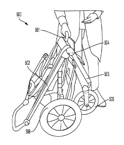
[0056] FIGS. 5A-B are photographs of a one-hand folding action for a one-
hand folding
stroller in accordance with embodiments of the invention. Turning now to FIG.
5A, a side
view of a one-hand folding stroller 500 being collapsed is shown. To fold the
stroller 500,
the user actuates a release handle 501, which in turn unlocks folding hinge
504. When
the folding hinge 504 unlocks, an upper member 502 and a lower member 503 move
down and in towards one another, thereby allowing upper frame member 502 and
lower
frame member 503 to move relative to each other. As shown in FIG. 5A, the
upper frame
member 502 and lower frame member 503 are moving towards each other, thereby
caus-
ing the stroller 500 to fold inwards towards itself along a central axis.
[0057] Turning now to FIG. 5B, a side view of the stroller 500 in the
collapsed position
is shown. In the collapsed position, the upper frame member 502 and the lower
frame
member 503 have moved towards each other and caused a front wheel 505 and rear
wheels 506 move in towards the central axis. Further, as shown in FIG. 5B, the
rear
wheels 506 have retracted towards the central axis, thereby further reducing
the footprint
of the stroller 500 in the collapsed position.
[0058] FIGS. 5A-B are illustrative pictures of a one-hand folding stroller
at various
stages of one-hand folding action and many configurations are appropriate. For
example,
11
8765293
Date Recue/Date Received 2023-09-19
the upper and lower members can collapse to various angles as appropriate to
the re-
quirements of specific applications of embodiments of the invention.
Release Handle Operation
[0059] FIG. 6 is a rendering of the operation of a release handle for a one-
hand folding
stroller in accordance with embodiments of the invention. In FIG. 6, a
perspective view of
a slide release handle assembly 600 being disengaged is shown. When release
handle
601 is actuated, slide locks 605 are disengaged from the crossbar locking
members 604
as described herein. Once the slide locks 605 are disengaged, seat frame 602
can be
disengaged from support crossbar 603 as described herein. Once disengaged, the
seat
frame 602 can be lifted to rotate about pivot points 606 in a direction away
from support
crossbar 603 as described herein.
[0060] FIG. 7 is a rendering of the operation of a release handle for a one-
hand folding
stroller in accordance with embodiments of the invention. A tab release handle
assembly
700 is shown in FIG. 7. Release handle 701 is actuated by sliding handle slide
member
706. Slide member 706 is coupled with a release tab 708, which is located near
a rivet
707. As the slide member 706 moves, it actuates the release tab 708, which
engages
with locking tab 709. The engagement of release tab 708 and locking tab 709
causes
locking tab 709 to disengage from the rivet 707. Once disengaged, the seat
frame 702
can be lifted to rotate about pivot points (not shown) in a direction away
from support
crossbar 703 as described herein.
[0061] FIGS. 6 and 7 are conceptual illustrations of the operation of a
release handle
in accordance with various embodiments of the invention. However, it should be
noted
that a variety of release handles, including those that disengage with frame
members of
the stroller, can be utilized as appropriate to the requirements of specific
applications of
embodiments of the invention.
[0062] Although the present invention has been described in certain
specific aspects,
many additional modifications and variations would be apparent to those
skilled in the art.
In particular, any of the various processes described above can be performed
in alterna-
tive sequences and/or in parallel in order to achieve similar results in a
manner that is
12
8765293
Date Recue/Date Received 2023-09-19
more appropriate to the requirements of a specific application. It is
therefore to be under-
stood that the present invention can be practiced otherwise than specifically
described
without departing from the scope and spirit of the present invention. Thus,
embodiments
of the present invention should be considered in all respects as illustrative
and not restric-
tive. It will be evident to the annotator skilled in the art to freely combine
several or all of
the embodiments discussed here as deemed suitable for a specific application
of the in-
vention. Throughout this disclosure, terms like "advantageous", "exemplary" or
"preferred"
indicate elements or dimensions which are particularly suitable (but not
essential) to the
invention or an embodiment thereof, and may be modified wherever deemed
suitable by
the skilled annotator, except where expressly required. Accordingly, the scope
of the in-
vention should be determined not by the embodiments illustrated, but by the
appended
claims and their equivalents.
13
8765293
Date Recue/Date Received 2023-09-19