Note: Descriptions are shown in the official language in which they were submitted.
CHANNEL STATE INFORMATION CSI REPORT MAPPING
METHOD, TERMINAL, AND NETWORK-SIDE DEVICE
CROSS-REFERENCE TO RELATED APPLICATIONS
[0001] This application claims priority to Chinese Patent
Application No.
202110336986.X, filed in China on March 29, 2021, which is incorporated herein
by
reference in its entirety.
TECHNICAL FIELD
[0002] This application relates to the field of communications
technologies, and
specifically, to a channel state information CSI report mapping method, a
terminal, and
a network-side device.
BACKGROUND
[0003] In a communications system, after a terminal reports
channel state
information (channel state information, CSI) to a base station, the base
station adjusts
communication scheduling and a transmission mode based on reported CSI
content, so
that the terminal can complete normal communication in the communications
system.
Therefore, the reporting of CSI is very important.
[0004] In the related art, before the terminal reports the
CSI, the terminal first
measures a channel state information reference signal (CSI Reference Signal,
CSI-RS)
or a synchronization signal and PBCH block (Synchronization Signal and PBCH
block,
SSB) configured or activated by a network-side device. Then the terminal
determines
content of the CSI report based on beam reporting and a beam report quantity
in a CSI
report configuration configured by the network-side device. The terminal maps
the
content of the CSI report to uplink control information (Uplink Control
Information,
CA 03213940 2023- 9- 28
UCI) according to a mapping rule configured by the network-side device, and
feeds
back the content of the CSI report to the network-side device through a PUCCH
or a
PUSCH, so that the base station subsequently establishes, with the terminal, a
communication transmission that the terminal can receive. When a beam
reporting type
of a CSI-RS resource is a group-based beam reporting type, the terminal
reports
information about a pair of beams that can be simultaneously received by the
terminal.
[0005] However, in a process of reporting the CSI by the
terminal, in a case that the
beam reporting type configured by the base station is group-based beam
reporting, there
is no suitable mapping manner for simultaneously reporting information about a
plurality of pairs of beams.
SUMMARY
[0006] Embodiments of this application provide a channel state
information CSI
report mapping method, a terminal, and a network-side device, to resolve a
problem
that there is no suitable mapping manner for simultaneously reporting a
plurality of
pairs of beams in a case that a beam reporting type configured by a base
station is a
group-based beam reporting type in a process of reporting CSI by a terminal.
[0007] According to a first aspect, a channel state
information CSI report mapping
method is provided. The method includes: feeding back, by a terminal, X CSI
reports
to a network-side device through a target channel according to a preset
mapping rule,
where the CSI report includes at least one of the following: information for
indicating
a beam reporting type and information about target beams; the target beams
include at
least one of the following: N pairs of first beams that can be simultaneously
received
by the terminal, and M second beams whose measurement values satisfy a
predetermined condition, where N is a positive integer greater than or equal
to 1, and X
and M are positive integers; and the preset mapping rule is a mapping rule
that matches
the beam reporting type.
[0008] According to a second aspect, a channel state
information CSI report
mapping apparatus is provided. The apparatus includes a feedback module. The
2
CA 03213940 2023- 9- 28
feedback module is configured to feed back X CSI reports to a network-side
device
through a target channel according to a preset mapping rule, where the CSI
report
includes at least one of the following: information for indicating a beam
reporting type
and information about target beams; the target beams include at least one of
the
following: N pairs of first beams that can be simultaneously received by a
terminal, and
M second beams whose measurement values satisfy a predetermined condition,
where
N is a positive integer greater than or equal to 1, and X and M are positive
integers; and
the preset mapping rule is a mapping rule that matches the beam reporting
type.
[0009] According to a third aspect, a channel state
information CSI report mapping
method is provided. The method includes: receiving, by a network-side device,
a CSI
report reported by a terminal; and parsing, by the network-side device, the
CSI report
based on a beam reporting type, where the CSI report includes at least one of
the
following: information for indicating the beam reporting type and information
about
target beams; the target beams include at least one of the following: N pairs
of first
beams that can be simultaneously received by the terminal, and M second beams
whose
measurement values satisfy a predetermined condition, where N is a positive
integer
greater than or equal to 1, and M is a positive integer; the beam reporting
type is
configured by the network-side device for the terminal, or determined by the
terminal
according to a preset rule of the network-side device; and the beam reporting
type
includes at least one of the following: group-based beam reporting, non-group-
based
beam reporting, and group-based and non-group-based hybrid beam reporting.
[0010] According to a fourth aspect, a channel state
information CSI report
mapping apparatus is provided. The apparatus includes a receiving module and a
parsing module. The receiving module is configured to receive a CSI report
reported
by a terminal. The parsing module is configured to parse the CSI report based
on a beam
reporting type, where the CSI report includes at least one of the following:
information
for indicating the beam reporting type and information about target beams; the
target
beams include at least one of the following: N pairs of first beams that can
be
simultaneously received by the terminal, and M second beams whose measurement
values satisfy a predetermined condition, where N is a positive integer
greater than or
3
CA 03213940 2023- 9- 28
equal to 1, and M is a positive integer; and the beam reporting type is
configured by a
network-side device for the terminal, or determined by the terminal according
to a
preset rule of a network-side device; and the beam reporting type includes at
least one
of the following: group-based beam reporting, non-group-based beam reporting,
and
group-based and non-group-based hybrid beam reporting.
[0011] According to a fifth aspect, a terminal is provided.
The terminal includes a
processor, a memory, and a program or instructions stored in the memory and
capable
of running on the processor. When the program or instructions are executed by
the
processor, the steps of the method according to the first aspect are
implemented.
[0012] According to a sixth aspect, a terminal is provided and includes a
processor
and a communications interface. The communications interface is configured to
feed
back X CSI reports to a network-side device through a target channel according
to a
preset mapping rule, where the CSI report includes at least one of the
following:
information for indicating a beam reporting type and information about target
beams;
the target beams include at least one of the following: N pairs of first beams
that can be
simultaneously received by the terminal, and M second beams whose measurement
values satisfy a predetermined condition, where N is a positive integer
greater than or
equal to 1, and X and M are positive integers; and the preset mapping rule is
a mapping
rule that matches the beam reporting type.
[0013] According to a seventh aspect, a network-side device is provided.
The
network-side device includes a processor, a memory, and a program or
instructions
stored in the memory and capable of running on the processor. When the program
or
instructions are executed by the processor, the steps of the method according
to the first
aspect are implemented.
[0014] According to an eighth aspect, a network-side device is provided and
includes a processor and a communications interface. The communications
interface is
configured to receive a CSI report reported by a terminal. The processor is
configured
to parse the CSI report based on a beam reporting type, where the CSI report
includes
at least one of the following: information for indicating the beam reporting
type and
information about target beams; the target beams include at least one of the
following:
4
CA 03213940 2023- 9- 28
N pairs of first beams that can be simultaneously received by the terminal,
and M
second beams whose measurement values satisfy a predetermined condition, where
N
is a positive integer greater than or equal to 1, and M is a positive integer;
the beam
reporting type is configured by the network-side device for the terminal, or
determined
by the terminal according to a preset rule of the network-side device; and the
beam
reporting type includes at least one of the following: group-based beam
reporting, non-
group-based beam reporting, and group-based and non-group-based hybrid beam
reporting.
[0015] According to a ninth aspect, a readable storage medium
is provided. The
readable storage medium stores a program or instructions. When the program or
instructions are executed by a processor, the steps of the method according to
the first
aspect are implemented, or the steps of the method according to the third
aspect are
implemented.
[0016] According to a tenth aspect, a chip is provided. The
chip includes a
processor and a communications interface. The communications interface is
coupled to
the processor. The processor is configured to run a program or instructions to
implement
the method according to the first aspect or implement the method according to
the third
aspect.
[0017] According to an eleventh aspect, a computer program or
program product is
provided. The computer program or program product is stored in a storage
medium.
The computer program or program product is executed by at least one processor
to
implement the steps of the method according to the first aspect or implement
the steps
of the method according to the third aspect.
[0018] In the embodiments of this application, the terminal
maps the X CSI reports
(the CSI report includes the information for indicating the beam reporting
type and/or
the information about the target beams) to uplink control information (Uplink
Control
Information, UCI) according to the preset mapping rule matching the beam
reporting
type, and feeds back the X CSI reports to the network-side device through the
target
channel (for example, a physical uplink control channel (Physical Uplink
Control
Channel, PUCCH) or a physical uplink shared channel (Physical Uplink Shared
5
CA 03213940 2023- 9- 28
Channel, PUSCH)), so that the network-side device performs communication and
transmission with the terminal based on a mapping result reported by the
terminal. In
the foregoing process, because the target beams include the N pairs of first
beams that
can be simultaneously received by the terminal, (N is a positive integer
greater than 1),
and/or the M second beams whose measurement values satisfy the predetermined
condition (M is a positive integer), in a case that the beam reporting type is
group-based
beam reporting, the method provided in the embodiments of this application can
enable
the terminal to simultaneously report a plurality of pairs of beams, instead
of reporting
only one pair of beams.
BRIEF DESCRIPTION OF DRAWINGS
[0019] FIG. 1 is a diagram of a system architecture of a
communications system
according to an embodiment of this application;
[0020] FIG. 2 is a first flowchart of a channel state
information CSI report mapping
method according to an embodiment of this application;
[0021] FIG. 3 is a first schematic diagram of a mapping process of a
channel state
information CSI report mapping method according to an embodiment of this
application;
[0022] FIG. 4 is a second schematic diagram of a mapping
process of a channel
state information CSI report mapping method according to an embodiment of this
application;
[0023] FIG. 5 is a third schematic diagram of a mapping process of a
channel state
information CSI report mapping method according to an embodiment of this
application;
[0024] FIG. 6 is a fourth schematic diagram of a mapping
process of a channel state
information CSI report mapping method according to an embodiment of this
application;
[0025] FIG. 7 is a second flowchart of a channel state
information CSI report
mapping method according to an embodiment of this application;
[0026] FIG. 8 is a first schematic diagram of a structure of a
channel state
information CSI report mapping apparatus according to an embodiment of this
application;
6
CA 03213940 2023- 9- 28
[0027] FIG. 9 is a second schematic diagram of a structure of
a channel state
information CSI report mapping apparatus according to an embodiment of this
application;
[0028] FIG. 10 is a schematic diagram of a structure of a
communications device
according to an embodiment of this application;
[0029] FIG. 11 is a schematic diagram of a hardware structure
of a terminal
according to an embodiment of this application; and
[0030] FIG. 12 is a schematic diagram of a hardware structure
of a network-side
device according to an embodiment of this application.
DESCRIPTION OF EMBODIMENTS
[0031] The following clearly describes the technical solutions
in the embodiments
of this application with reference to the accompanying drawings in the
embodiments of
this application. Apparently, the described embodiments are only some rather
than all
of the embodiments of this application. All other embodiments obtained by a
person of
ordinary skill in the art based on the embodiments of this application shall
fall within
the protection scope of this application.
[0032] The terms "first", "second", and the like in this
specification and claims of
this application are used to distinguish between similar objects instead of
describing a
specific order or sequence. It should be understood that the terms used in
this way are
interchangeable in appropriate circumstances, so that the embodiments of this
application can be implemented in other orders than the order illustrated or
described
herein. In addition, objects distinguished by "first" and "second" usually
fall within one
class, and a quantity of objects is not limited. For example, there may be one
or more
first objects. In addition, the term "and/or" in the specification and claims
indicates at
least one of connected objects, and the character "I" generally represents an
"or"
relationship between associated objects.
[0033] It should be noted that technologies described in the
embodiments of this
application are not limited to a long term evolution (Long Term Evolution,
LTE)/LTE-
7
CA 03213940 2023- 9- 28
Advanced (LTE-Advanced, LTE-A) system, and can also be used in other wireless
communications systems, such as code division multiple access (Code Division
Multiple Access, CDMA), time division multiple access (Time Division Multiple
Access, TDMA), frequency division multiple access (Frequency Division Multiple
Access, FDMA), orthogonal frequency division multiple access (Orthogonal
Frequency
Division Multiple Access, OFDMA), single-carrier frequency-division multiple
access
(Single-carrier Frequency-Division Multiple Access, SC-FDMA), and other
systems.
The terms "system" and "network" in the embodiments of this application are
usually
used interchangeably. The described technologies may be used for the foregoing
systems and radio technologies, and may also be used for other systems and
radio
technologies. However, in the following descriptions, the new radio (New
Radio, NR)
system is described for an illustrative purpose, and NR terms are used in most
of the
following descriptions. These technologies may also be applied to other
applications
than an NR system application, for example, a 6th Generation (6th Generation,
6G)
communications system.
[0034] FIG. 1 is a diagram of a system architecture of a
wireless communications
system to which an embodiment of this application may be applied. The wireless
communications system includes a terminal 11 and a network-side device 12. The
terminal 11 may also be referred to as a terminal device or a user terminal
(User
Equipment, UE). The terminal 11 may be a terminal-side device such as a mobile
phone,
a tablet personal computer (Tablet Personal Computer), a laptop computer
(Laptop
Computer) or a notebook computer, a personal digital assistant (Personal
Digital
Assistant, PDA), a palmtop computer, a netbook, an ultra-mobile personal
computer
(ultra-mobile personal computer, UMPC), a mobile Internet device (Mobile
Internet
Device, MID), a wearable device (Wearable Device), a vehicular user equipment
(VUE),
or a pedestrian user equipment (PUE). The wearable device includes a smart
watch, a
smart band, an earphone, glasses, or the like. It should be noted that a
specific type of
the terminal 11 is not limited in the embodiments of this application. The
network-side
device 12 may be a base station or a core network. The base station may be
referred to
as a NodeB, an evolved NodeB, an access point, a base transceiver station
(Base
8
CA 03213940 2023- 9- 28
Transceiver Station, BTS), a radio base station, a radio transceiver, a basic
service set
(Basic Service Set, BSS), an extended service set (Extended Service Set, ESS),
a NodeB,
an evolved NodeB (eNB), a home NodeB, a home evolved NodeB, a WLAN access
point, a Wi-Fi node, a transmission and reception point (Transmitting
Receiving Point,
TRP), or another appropriate term in the art, as long as the same technical
effect is
achieved. The base station is not limited to specific technical terms. It
should be noted
that in the embodiments of this application, only a base station in an NR
system is used
as an example, but a specific type of the base station is not limited.
[0035] The following describes the terms used in the
embodiments.
[0036] 1. Beam reporting
[0037] In a high-frequency (such as a frequency band above 6
gigahertz (GHz))
scenario of a fifth generation (5th generation, 5G) communications system
(which may
also be known as a new radio (new radio, NR) communications system) or a
communications system after 5G, a signal can be transmitted between a base
station
and a terminal by using a millimeter-wave frequency band. Because the
millimeter-
wave frequency band has characteristics of large attenuation and a weak
diffraction
capability, problems such as significant signal fading and path loss increase
are likely
to occur when the signal is transmitted by using the millimeter-wave frequency
band.
To avoid these problems, an analog beamforming technology is used between the
base
station and the terminal to transmit the signal. For example, the base station
may
centralize signals on one transmit beam and send the signals to the terminal,
and the
terminal may receive the signals on a receive beam corresponding to the
transmit beam.
This improves channel quality of a transmission channel between the base
station and
the terminal, and overcomes the problems of significant signal fading and path
loss
increase caused by high-frequency communication.
[0038] In the related art, there are mainly two types of beam
reporting: group-based
beam reporting and non-group-based beam reporting. Group-based beam reporting
means that a terminal reports information about beams that can be
simultaneously
received by the terminal. Currently, a protocol supports reporting of only two
CRIs or
SSBRIs and corresponding layer 1 measurement values (L 1 -RSRPs or L 1 -SINRs)
9
CA 03213940 2023- 9- 28
thereof. Non-group-based beam reporting means that the terminal reports
information
about a beam whose layer 1 measurement value (L1 -RSRPs or L1-SINRs) is
largest.
Currently, a protocol supports reporting of up to four CRTs or SSBRIs and
corresponding Li -RSRPs or Ll-SINRs thereof, and does not require that beams
should
be simultaneously received by the terminal.
[0039] 2. CSI report mapping manner
[0040] In the related art, if a groupBasedBeamReporting field
is configured in a
CSI report configuration (CSI Report Config) and a report quantity field is
configured
as "cri-rsrp" or "cri-sinr", it indicates that the current CSI report includes
information
about beams.
[0041] When the groupBasedBeamReporting field is "enabled", UE
can report only
one pair of beams, including two CMR identifiers (CRIs or SSBRIs) and
corresponding
L 1 -RSRP or L 1 -SINR values thereof. When the groupBasedBeamReporting field
is
"disabled", the UE may report CMR identifiers corresponding to four beams and
corresponding L1-RSRP or L1-SINRs thereof.
[0042] When a beam report quantity is greater than 1,
differential reporting is
performed on a largest L 1 -RSRP or L1-SINR value and other L1-RSRP values or
Ll -
SINR values than the largest value. A specific rule for mapping a CSI report
(Li -RSRP)
to UCI is shown in Table 1, and a similar rule is applied to the L 1 -SINR. It
should be
noted that a CRI or SSBRI position corresponds to an RSRP position, and CRI or
SSBRI #1 corresponds to RSRP #1, and RSRP #1 is a largest one of the four
RSRPs.
Table 1
CSI report number CSI fields
CRI or SSBRI #1 as in Table 6.3.1.1.2-6, if reported
CRI or SSBRI #2 as in Table 6.3.1.1.2-6, if reported
CSI report #n CRI or SSBRI #3 as in Table 6.3.1.1.2-6,
if reported
CRI or SSBRI #4 as in Table 6.3.1.1.2-6, if reported
RSRP #1 as in Table 6.3.1.1.2-6, if reported
CA 03213940 2023- 9- 28
Differential RSRP #2 as in Table 6.3.1.1.2-6, if reported
Differential RSRP #3 as in Table 6.3.1.1.2-6, if reported
Differential RSRP #4 as in Table 6.3.1.1.2-6, if reported
[0043]
Table 2 shows quantities of UCI bits of a CMR identifier and an Ll-RSRP.
A quantity of UCI bits of an Ll-SINR is similar.
11
CA 03213940 2023- 9- 28
Table 2
Field Bitwidth
CRI [loWICsi-R11
SSBRI [logksli
RSRP 7
Differential RSRP 4
[0044] KC:SI-RS is a quantity of CSI-RS resources configured
in one CSI-RS
resource configuration, and Icss8 is a quantity of SSB resources configured in
one SSB
resource set. A current protocol supports configuring a maximum of 64 RS
resources in
one CMR (CSI-RS or SSB) set.
[0045] A channel state information CSI report mapping method
provided in the
embodiments of this application is hereinafter described in detail by using
some
embodiments and application scenarios thereof with reference to the
accompanying
drawings.
[0046] FIG. 2 is a schematic flowchart of a channel state
information CSI report
mapping method according to an embodiment of this application. As shown in
FIG. 2,
the method is applied to UE, and the channel state information CSI report
mapping
method may include step 201.
[0047] Step 201: A terminal feeds back X CSI reports to a network-side
device
through a target channel according to a preset mapping rule.
[0048] In this embodiment of this application, the CSI report
includes at least one
of the following: information for indicating a beam reporting type and
information
about target beams.
[0049] In this embodiment of this application, the preset mapping rule is a
mapping
rule that matches the beam reporting type.
12
CA 03213940 2023- 9- 28
[0050] In this embodiment of this application, the beam
reporting type may include:
group-based beam reporting, non-group-based beam reporting, and group-based
and
non-group-based hybrid beam reporting.
[0051] In this embodiment of this application, the beam
reporting type is configured
by the network-side device for the terminal, or determined by the terminal
according to
a preset rule of the network-side device.
[0052] For example, the preset rule is a rule for the terminal
to determine, based on
an actual measurement situation of CSI-RS or SSB resources configured by the
network-side device, which specific beam reporting type is to be used. For
example,
when the terminal detects that, in the CSI-RS resources configured by the
network-side
device, there are two pairs of beams that can be simultaneously received and
two beams
with very large layer 1 measurement values, if a sum of layer 1 measurement
values of
one pair of beams that can be simultaneously received is smaller than a
smallest one of
layer 1 measurement values of two beams that cannot be simultaneously
received,
hybrid beam reporting is used; otherwise, group-based beam reporting is used.
[0053] In this embodiment of this application, the target
beams include at least one
of the following: N pairs of first beams that can be simultaneously received
by the
terminal, and M second beams that satisfy a predetermined condition, where N
is a
positive integer greater than or equal to 1, and X and M are positive
integers.
=
'0054] In this way, in the process of reporting CSI by the
terminal, the following
problem can be avoided: The terminal can only select, based on the beam
reporting type
configured by the network-side device, a beam that satisfies a corresponding
condition
for reporting, and cannot implement beam reporting and flexible switching
between
application scenarios corresponding to the reported beams. The terminal can
implement
group-based and non-group-based hybrid beam reporting. In addition, the
terminal can
autonomously perform beam reporting based on the beam reporting type
determined by
the preset rule of the network-side device, so that the determination of the
beam
reporting type is more diverse.
[0055] Optionally, in this embodiment of this application,
values of M and N can
be configured by the network-side device by using radio resource control
(Radio
13
CA 03213940 2023- 9- 28
Resource Control, RRC) signaling, or configured by the network-side device by
using
RRC signaling, and selected, determined, or modified by using a medium access
control
control element (Medium Access Control Control Element, MAC-CE).
[0056] Optionally, in this embodiment of this application, the
information about the
target beams includes at least one of the following: target CSI measurement
resource
indicators are CSI reference signal resource indicators CRIs or system
synchronization
block resource indicators SSBRIs, and measurement values of target CSI
measurement
resources are layer 1 measurement values.
[0057] For example, the measurement values of the target CSI
measurement
resources are layer 1 measurement values.
[0058] For example, each of the target CSI measurement
resource indicators
corresponds to a measurement value of one CSI measurement resource. The
measurement value may be used to determine communication quality of a beam
associated with the target CSI measurement resource indicator.
[0059] In an example, the layer 1 measurement value may be layer 1
reference
signal received power (Layer 1 reference signal received power, Li -RSRP),
that is, Ll-
RSRP, or a layer 1 signal to interference plus noise ratio (Layer 1 Signal to
Interference
plus Noise Ratio, Ll -SINR), that is, an L1-SINR.
[0060] For example, the target CSI measurement resource
indicators may be used
to provide auxiliary information for beam scheduling to the network-side
device.
[0061] For example, the target CSI measurement resource
indicators may include:
CSI-RS resource indicators (CSI-RS Resource Indicators, CRIs), or SSB resource
indicators (SSB Resource Indicators, SSBRIs).
[0062] In this embodiment of this application, the
predetermined condition refers
to second beams whose measurement values are ranked top M among all the second
beams. Optionally, for example, the terminal receives and measures a plurality
of CSI-
RS signals corresponding to resources indicated by a plurality of CSI-RS
resource
indicators configured by the network-side device. After receiving and
measuring the
plurality of CSI-RS signals corresponding to the resources indicated by the
plurality of
CSI-RS resource indicators configured by the network-side device, the terminal
selects,
14
CA 03213940 2023- 9- 28
from the plurality of CSI-RS signals, CSI-RS signals whose measurement values
are
ranked top M, and then obtains corresponding M CSI-RS resource indicators.
Then the
terminal selects M CSI-RS resource indicators, where the M CSI-RS resource
indicators are sorted based on measurement values corresponding to the CSI-RS
signals,
and there is a one-to-one correspondence between a measurement value of each
CSI-
RS signal and a corresponding resource indicator of the CSI-RS signal in an
arrangement position, where a resource indicator of a CSI-RS signal with a
largest
measurement value is arranged in a first position, and resource indicators of
the selected
M CSI-RS signals and corresponding measurement values thereof are used as
information about the second beams. Similarly, for example, the terminal
receives and
measures a plurality of SSB signals corresponding to resources indicated by a
plurality
of SSB resource indicators configured by the network-side device. After
receiving and
measuring the plurality of SSB signals corresponding to the resources
indicated by the
plurality of SSB resource indicators configured by the network-side device,
the terminal
selects, from the plurality of SSB signals, SSB signals whose measurement
values are
ranked top M, and then obtains corresponding M SSB resource indicators. Then
the
terminal selects M SSB resource indicators, where the M SSB resource
indicators are
sorted based on measurement values corresponding to the SSB signals, and there
is a
one-to-one correspondence between a measurement value of each SSB signal and a
corresponding resource indicator of the SSB signal in an arrangement position,
where
a resource indicator of an SSB signal with a largest measurement value is
arranged in a
first position, and resource indicators of the selected M SSB signals and
corresponding
measurement values thereof are used as information about the second beams.
[0063] Example 1: If M is equal to 4, in a case that the
terminal receives 10 CSI-
RS signals, the terminal measures and calculates received power or signal to
interference plus noise ratios of the 10 CSI-RS signals, and sorts the 10 CSI-
RS signals
based on layer 1 reference signal received power or layer 1 signal to
interference plus
noise ratios, where resource indicators and measurement values corresponding
to top
four CSI-RS signals constitute information about the second beams.
CA 03213940 2023- 9- 28
[0064] In this embodiment of this application, the target
channel may include a
PUCCH or a PUSCH.
[0065] It may be understood that after receiving a CSI
measurement resource
configured by the network-side device, the terminal receives and measures a
CSI-RS
signal or an SSB signal (hereinafter referred to as a reference signal) on the
CSI
measurement resource to obtain a measurement value of the reference signal,
and then
determines, based on the measurement value, CSI-related parameters or beam
information required in a communication process of the network-side device as
content
of the CSI report, and then reports the CSI report to the network-side device
through
the PUCCH or PUSCH, and the network-side device performs communication with
the
terminal based on a communication mode indicated in the CSI report. In the
process of
reporting the CSI report to the network-side device through the PUCCH or
PUSCH, it
is necessary to perform UCI mapping according to the mapping rule preset by
the
network-side device, and then reporting of the CSI report can be completed.
[0066] In this embodiment of this application, different mapping rules may
be used
to perform UCI mapping based on different CSI reports. Optionally, the UCI
mapping
rule depends on the information in the CSI report (for example, the
information for
indicating the beam reporting type in the CSI report, and the information
about the
target beams in the CSI report). If the information in the CSI report is
different, the
mapping rule for UCI mapping is also different correspondingly.
[0067] The terminal provided in this embodiment of this
application maps the X
CSI reports (the CSI reports include the information for indicating the beam
reporting
type and/or the information about the target beams) according to the preset
mapping
rule matching the beam reporting type, and feeds back the X CSI reports to the
network-
side device through the target channel (for example, the physical uplink
control channel
(Physical Uplink Control Channel, PUCCH) or the physical uplink shared channel
(Physical Uplink Shared Channel, PUSCH)), so that the network-side device
performs
communication and transmission with the terminal based on a mapping result
reported
by the terminal. In the foregoing process, because the target beams include
the N pairs
of first beams that can be simultaneously received by the terminal, (N is a
positive
16
CA 03213940 2023- 9- 28
integer greater than 1), and/or the M second beams whose measurement values
satisfy
the predetermined condition (M is a positive integer), in a case that the beam
reporting
type is group-based beam reporting, the method provided in this embodiment of
this
application can enable the terminal to simultaneously report a plurality of
pairs of
beams, instead of reporting only one pair of beams.
[0068] Optionally, in this embodiment of this application,
when the beam reporting
type is configured by the network-side device for the terminal, the beam
reporting type
may be modified by the network-side device by using a MAC-CE.
[0069] In this way, modifying the beam reporting type by using
the MAC-CE can
avoid problems of high RRC signaling overheads and inflexible switching in
this
manner because a terminal can implement sTRP-mTRP switching only after a
"group-
based beam reporting (groupBasedBeamReporting)" field in a CSI report
configuration
is reconfigured by using RRC signaling in the related art.
[0070] Optionally, in this embodiment of this application, in
a case that the CSI
report includes the target CSI measurement resource indicators, the channel
state
information CSI report mapping method provided in this embodiment of this
application further includes the following step 202.
[0071] Step 202: The terminal encodes the target CSI
measurement resource
indicators based on a preset encoding mode.
[0072] For example, the target CSI measurement resource indicators include
all
target CSI measurement resource indicators or a part of target CSI measurement
resource indicators.
[0073] For example, the CSI measurement resource indicators
may be CRIs or
SSBRIs.
[0074] The preset encoding mode includes at least one of the following:
the terminal performs encoding based on a quantity of channel measurement
resources (Channel Measurement Resource, CMR) configured in a CSI measurement
resource setting;
the terminal performs encoding based on a quantity of CMRs configured in
a CSI measurement resource set;
17
CA 03213940 2023- 9- 28
the terminal performs encoding based on a quantity of CMRs configured in
a CSI measurement resource subset in the CSI measurement resource set; and
the terminal performs joint encoding based on CMR resources.
100751 For example, in a case that the preset encoding mode is
that the terminal
performs encoding based on the quantity of CMRs configured in the CSI
measurement
resource setting, if the CSI measurement resource indicators are CRIs, and a
total
quantity of CMRs configured in the CSI measurement resource setting is K, a
resource
occupied by one CRI is Flog2K11 bits.
[0076] For example, in a case that the terminal performs
encoding based on the
quantity of CMRs configured in the CSI measurement resource set, if the CSI
measurement resource indicators are CRIs, and Z CSI measurement resource sets
are
configured in the CSI measurement resource setting, where each CSI measurement
resource set includes Ki channel measurement resources, and different CSI
measurement resource sets correspond to different CORESETPoolIndexes, the
following manner 1 or manner 2 may be used to determine a correspondence
between
a currently reported target CSI measurement resource indicator and a CSI
measurement
resource set.
[0077] Manner 1: The terminal extends a field of the target
CSI measurement
resource indicator by log2 Z bits to indicate a correspondence between a
currently
reported CRI or SSBRI and the CSI measurement resource set. Fields of the
target CSI
measurement resource indicators may be fields of a part of CSI measurement
resource
indicators in the target CSI measurement resource indicators, or may be fields
of all
CSI measurement resource indicators in the target CSI measurement resource
indicators.
[0078] For example, in a case that the target CSI measurement
resource indicator is
a CRI, the terminal extends a field of the CRI by Flog2 Zil bits to add an
identifier of
a CMR set to which the CRI belongs. In this case, a resource that one CRI
needs to
occupy, that is, a quantity of corresponding UCI bits, is rtog2 Ki0+Flog2Z0
18
CA 03213940 2023- 9- 28
[0079] Manner 2: Add a field before a first CSI measurement
resource indicator,
where the field is used to indicate a CSI measurement resource set
corresponding to the
first CSI measurement resource indicator, and remaining CSI measurement
resource
indicators are mapped and arranged according to the preset mapping rule, and
determine
a correspondence between the first CSI measurement resource indicator and the
CSI
measurement resource set, where the first CSI measurement resource indicator
is an
identifier of a CMR with a largest Ll -RSRP or Ll -SINR value.
[0080] Regarding the foregoing manner 2, the correspondence
between the target
CSI measurement resource indicator and the CSI measurement resource set may be
indicated in the manner in the following example 1.
[0081] Example 1: When the quantity of CSI measurement
resource sets configured
by the network-side device in the CSI measurement resource setting is Z=2, and
the
beam report quantity is 4, and the CSI measurement resource indicators are
CRIs (that
is, the CSI measurement resource indicators include CRI #1, CRI #2, CRI #3,
and CRI
#4), the terminal may determine a correspondence between the target CSI
measurement
resource indicators and CSI measurement resource sets in the manner shown in
FIG. 3.
When two CRIs are mapped to UCI as a group, and the two CRIs correspond to
different
CSI measurement resource sets, if a resource indicator field of newly added
CRI #1 is
0, it indicates that a CMR corresponding to CRI #1 corresponds to CSI
measurement
resource set 0, and a CMR corresponding to CRI #2 paired with CRI #1
corresponds to
CSI measurement resource set 1. Remaining CRI groups are arranged based on a
correspondence similar to a correspondence between CRIs in the first CRI group
and
TRPs. For example, a CMR corresponding to CRI #3 corresponds to CSI
measurement
resource set 0, and a CMR corresponding to CRI #4 corresponds to CSI
measurement
resource set 1.
[0082] For example, in a case that the foregoing preset
encoding mode is that the
terminal performs encoding based on the quantity of CMRs configured in the CSI
measurement resource subset in the CSI measurement resource set, the terminal
may
configure one CSI measurement resource set in one CSI measurement resource
configuration, and may divide CMRs in the CSI measurement resource set into P
CSI
19
CA 03213940 2023- 9- 28
measurement resource subsets, where each CSI measurement resource subset is
associated with a different control resource set pool identifier (CORESETPool
Index).
[0083] Further, the terminal may determine a correspondence
between the currently
reported target CSI measurement resource indicator and a CSI measurement
resource
subset in the following manner 3 or manner 4.
[0084] Manner 3: Extend the field of the target CSI
measurement resource indicator
by log2 P bits to indicate the correspondence between the currently reported
target
CSI measurement resource indicator and the CSI measurement resource subset.
[0085] Manner 4: Add a field to the UCI, where the field is
used to indicate a CSI
measurement resource subset corresponding to a first CSI measurement resource
indicator, and the remaining CSI measurement resource indicators are mapped
and
arranged according to the preset mapping rule of the network, and determine a
correspondence between the first CSI measurement resource indicator and the
CSI
measurement resource subset, where the first CSI measurement resource
indicator is an
identifier of a CMR with a largest Ll -RSRP or L1-SINR value.
[0086] For example, in a case that the preset encoding mode is
that the terminal
performs joint encoding based on CMR resources, all CSI measurement resource
indicators are jointly encoded and mapped based on the quantity of CMRs, that
is, one
CSI measurement resource indicator corresponds to one or more CMRs, and each
of
the CMRs is associated with different CORESETPoolIndexes.
[0087] Further, the terminal may determine the correspondence
between the
currently reported target CSI measurement resource indicator and the CSI
measurement
resource subset in the following manner 5.
[0088] Manner 5: The network-side device configures all CMRs
in pairs in advance
to generate L CMR resource pairs, where L is a positive integer. Different
CMRs in
different CMR resource pairs correspond to different CORESETPoolIndexes. In
this
case, the target CSI measurement resource indicators are jointly encoded
identifiers of
the CMR resource pairs.
CA 03213940 2023- 9- 28
[0089] Example 2: In a case that the target CSI measurement
resource indicators
are CRIs, assuming that the total quantity of CMRs is 4 and that a quantity of
CORESETPoolIndexes is 2, values of CORESETPoolIndexes are 0 or 1, and every
two
CMRs are associated with one CORESETPoolIndex. In this case, the network-side
device may preconfigure the CMRs in pairs, as shown in Table 3, and the
terminal needs
to report only one CRI when performing reporting.
21
CA 03213940 2023- 9- 28
Table 3
CRI 1 (CMR 1, CMR 3)
CORESETPoolIndex #0
CRI 2 (CMR 1, CMR 4)
CRI 3 (CMR 2, CMR 3)
CORESETPoolIndex #1
CRI 4 (CMR 2, CMR 4)
[0090] For example, in a case that the foregoing target CSI
measurement resource
indicators are a part of measurement resource indicators, all the foregoing
CSI
measurement resource indicators may include a plurality of parts of
measurement
resource indicators. Correspondingly, a preset encoding mode of each part of
measurement resource indicators may be different.
[0091] In an example, the preset encoding modes of the target
CSI measurement
resource indicators may include the following two modes: the terminal performs
encoding based on the quantity of CMRs configured in the CSI measurement
resource
setting; and the terminal performs encoding based on the quantity of CMRs
configured
in the CSI measurement resource set. For example, if the target CSI
measurement
resource indicators include two parts of CSI measurement resource indicators,
an
encoding mode of a first part of CSI measurement resource indicators is: the
terminal
performs encoding based on the quantity of CMRs configured in the CSI
measurement
resource setting, and an encoding mode of a second part of CSI measurement
resource
indicators is: the terminal performs encoding based on the quantity of CMRs
configured
in the CSI measurement resource set.
[0092] In an example, the preset encoding modes of the target
CSI measurement
resource indicators may include the following two modes: the terminal performs
encoding based on the quantity of CMRs configured in the CSI measurement
resource
set; and the terminal performs encoding based on the quantity of CMRs
configured in
the CSI measurement resource subset in the CSI measurement resource set. For
example, if the target CSI measurement resource indicators include two parts
of CSI
measurement resource indicators, an encoding mode of a first part of CSI
measurement
resource indicators is: the terminal performs encoding based on the quantity
of CMRs
22
CA 03213940 2023- 9- 28
in the CSI measurement resource set, and an encoding mode of a second part of
CSI
measurement resource indicators is: the terminal performs encoding based on
the
quantity of CMRs configured in the CSI measurement resource subset in the CSI
measurement resource set.
[0093] In this way, in the encoding mode of the foregoing target CSI
measurement
resource indicators (such as CRIs or SSBRIs), it is possible to avoid a
problem that the
network-side device cannot identify which TRP measurement resources having a
same
CSI measurement resource indicator in the CSI report come from if a plurality
of CSI
measurement resource sets are configured in a potential multi-TRP CSI
framework to
perform a multi-TRP CSI measurement and the CSI measurement resource
indicators
are encoded and mapped based on a resource quantity of CSI measurement
resources
in the measurement resource set because the CSI measurement resource
indicators in
the current CSI report are encoded and mapped based on a quantity of CSI
measurement
resources in a channel measurement resource set (for example, a CMR set).
[0094] Optionally, in this embodiment of this application, in a case that
the beam
reporting type is configured by the network-side device, or determined by the
terminal
according to the preset rule of the network-side device,
if the beam reporting type is group-based beam reporting, the terminal
selects to report information about the N pairs of first beams that can be
simultaneously
received by the terminal, where target CSI measurement resource indicators in
information about each pair of first beams correspond to different CSI
measurement
resources;
if the beam reporting type is non-group-based beam reporting, the terminal
selects to report information about the M second beams whose measurement
values
satisfy the predetermined condition; or
if the beam reporting type includes group-based and non-group-based
hybrid beam reporting, the terminal selects to report information about Q
pairs of first
beams and information about W second beams.
23
CA 03213940 2023- 9- 28
[0095] For example, Q is less than or equal to N, W is less
than or equal to M, Q
and W can be configured by the network-side device or set according to a
preset rule,
and Q and W are positive integers.
[0096] For example, the CSI measurement resources include any
one of the
following: a CSI measurement resource setting, a CSI measurement resource set,
and a
CSI measurement resource subset.
[0097] For example, the foregoing preset rule may refer to the
preset rule described
above, or the terminal may first determine, based on an actual measurement
situation,
a ratio of Q to W from a ratio set preset by the network-side device, and then
determine
values of Q and W with reference to a maximum beam report quantity Y
configured by
the network-side device or used by default.
[0098] For example, the ratio set preset by the network-side
device includes three
ratios 2:1, 1:1, and 1:2, and the three ratios correspond to three terminal
measurement
states respectively. When a sum of layer 1 measurement values of beams that
can be
simultaneously received is greater than a largest layer 1 measurement value of
beams
that cannot be simultaneously received, the terminal selects Q:W=2:1; when a
sum of
layer 1 measurement values of beams that can be simultaneously received is
equal to a
largest layer 1 measurement value of beams that cannot be simultaneously
received, the
terminal selects Q:W=1:1; or when a sum of layer 1 measurement values of beams
that
can be simultaneously received is less than a largest layer 1 measurement
value of
beams that cannot be simultaneously received, the terminal selects Q:W=1:2.
After
determining the ratio of Q to W, the terminal can determine specific values of
Q and W
based on the maximum beam report quantity Y configured by the network-side
device
or used by default.
[0099] For example, if the beam reporting type is group-based beam
reporting, the
terminal selects and determines to report the information about the N pairs of
first
beams that can be simultaneously received by the terminal, where CRIs/SSBRIs
in each
pair of first beams correspond to different CSI measurement resource settings,
or CSI
measurement resource sets, or CSI measurement resource subsets.
24
CA 03213940 2023- 9- 28
100100] For example, if the beam reporting type is non-group-based beam
reporting,
the terminal selects and determines to report the information about the M
second beams
whose layer 1 measurement values satisfy the predetermined condition.
[00101] For example, if the beam reporting type includes group-based and non-
group-based hybrid beam reporting, the terminal selects and determines to
report the
information about N pairs of first beams that can be simultaneously received
and the
information about the M second beams whose layer 1 measurement values satisfy
the
predetermined condition.
[00102] Optionally, in this embodiment of this application, in a case that the
beam
reporting type is determined by the terminal according to the preset rule of
the network-
side device, the beam reporting type can be indicated in either of the
following manners:
the beam reporting type is indicated by a target field in the CSI report; and
the beam reporting type is indicated based on a value relationship between
a measurement value of a CSI measurement resource and a target measurement
threshold in the CSI report, where
the target measurement threshold is configured by the network-side device,
or preset by the network-side device and the terminal.
[00103] For example, when the beam reporting type is indicated by the target
field
in the CSI report, the beam reporting type may be indicated in the following
manner a
and manner b:
[00104] Manner a: The terminal extends the field of the target CSI measurement
resource indicator by two bits to indicate that the corresponding beam
reporting type is
group-based beam reporting, non-group-based beam reporting, or group-based and
non-
group-based hybrid beam reporting.
[00105] Example 3: The beam reporting type is group-based and non-group-based
hybrid beam reporting, measurement values are L 1 -RSRP values, and the target
CSI
measurement resource indicators are CRI #1, CRI #2, CRI #3, and CRI #4. In
this case,
as shown in (a) in FIG. 4, the terminal extends a CRI field in which each CSI
measurement resource indicator in the target CSI measurement resource
indicators is
located, by two bits to indicate a beam reporting type corresponding to the
CSI
CA 03213940 2023- 9- 28
measurement resource indicator, where 1 refers to group-based beam reporting,
0 refers
to non-group-based beam reporting, and 2 refers to group-based and non-group-
based
hybrid beam reporting. In this case, the network-side device can correctly
obtain all
beam reporting types of the first beams and the beam reporting types of the
second
beams by reading CRI fields.
[00106] Manner b: The terminal adds a 1-bit field to fields of the target CSI
measurement resource indicators to indicate the beam reporting type
corresponding to
the first CSI measurement resource indicator (for example, a CRI), so that the
network-
side device can distinguish between target CSI measurement resource indicators
corresponding to different beam reporting types and layer 1 measurement values
corresponding to the target CSI measurement resource indicators.
[00107] Example 4: As shown in (b) in FIG. 4, the beam reporting type is group-
based and non-group-based hybrid beam reporting, measurement values are L 1 -
RSRP
values, and the target CSI measurement resource indicators are CRI #1, CRI #2,
CRI
#3, and CRI #4. In this case, the terminal can arrange, based on L 1 -RSRP
values, first
beams whose beam reporting type is group-based beam reporting and second beams
whose beam reporting type is non-group-based beam reporting. Because a largest
value
of non-group-based reported L 1 -RSRP is greater than or equal to a largest
value of
group-based reported L 1 -RSRP, the second beams, that is, CRI #1 and CRI #2,
are
preferentially arranged. To facilitate the network-side device to know the
beam
reporting types of the first beams and the second beams, a 1-bit indicator
field (that is,
the foregoing target field) can be added in a start position of the UCI
mapping (as shown
in (a) in FIG. 4), where 1 refers to group-based beam reporting, and 0 refers
to non-
group-based beam reporting. In this field, 1 or 0 is used to indicate the beam
reporting
type of CRI #1, and the network-side device can correctly obtain all beam
information
based on the indicator field and quantities of the first beams and the second
beams. It
should be noted that when CRI #1 is a common value selected under two
reporting
hypotheses, the information about the first beams reported under the group-
based
reporting hypothesis type is arranged preferentially.
26
CA 03213940 2023- 9- 28
100108] For example, when the beam reporting type is indicated based on the
value
relationship between the measurement value of the CSI measurement resource and
the
target measurement threshold in the CSI report, the beam reporting type may be
indicated in the following manner c.
[00109] Manner c: The network-side device presets the target measurement
threshold for the measurement value. The measurement value may be a layer 1
measurement value, and the target measurement threshold may be a differential
threshold of the layer 1 measurement value.
[00110] In an example, when differences between measurement values of all
beams
received by the terminal (such as layer 1 measurement values of CRIs or layer
1
measurement values of SSBRIs) and the largest measurement value are all
greater than
or equal to the target measurement threshold, UCI mapping is performed on
content in
the CSI report according to the group-based beam reporting. Correspondingly,
after the
network-side device receives the measurement values of the beams and
calculates
differences between the measurement values and the largest measurement value,
if all
the differences are greater than or equal to the target measurement threshold,
it can be
considered that the beam information is measured and reported according to the
group-
based beam reporting.
[00111] In another example, when differences between measurement values of all
beams received by the terminal (such as layer 1 measurement values of CRIs or
layer 1
measurement values of SSBRIs) and the largest measurement value are all less
than the
target measurement threshold, UCI mapping is performed on content in the CSI
report
according to the non-group-based beam reporting. Correspondingly, after the
network-
side device receives the measurement values of the beams and calculates
differences
between the measurement values and the largest measurement value, if all the
differences are less than the target measurement threshold, it can be
considered that the
beam information is measured and reported according to the non-group-based
beam
reporting.
[00112] Further, in the foregoing manner c, if the beam information reported
by the
terminal needs to be reported in a form of beam pairs, and differences between
27
CA 03213940 2023- 9- 28
measurement values of first beams in all beam pairs (such as layer 1
measurement
values of CRIs or layer 1 measurement values of SSBRIs) and measurement values
of
second beams in the beam pairs are all set to be greater than or equal to the
target
measurement threshold. In this case, UCI mapping is performed on the content
in the
CSI report according to the group-based beam reporting. Conversely, the
terminal can
set all differences between measurement values of first beams in all beam
pairs (such
as layer 1 measurement values of CRIs or layer 1 measurement values of SSBRIs)
and
measurement values of second beams in the beam pairs to be less than the
target
measurement threshold. In this case, UCI mapping is performed on the content
in the
CSI report according to the non-group-based beam reporting.
[00113] Correspondingly, after receiving the beam pairs, the network-side
device
calculates a difference between the measurement value of the first beam and
the
measurement value of the second beam in each beam pair. If the difference is
greater
than or equal to the target measurement threshold, it can be considered that
beam
information is reported according to group-based beam reporting. Conversely,
if the
difference is less than the target measurement threshold, it can be considered
that beam
information is reported according to non-group-based beam reporting.
[00114] Further, in a case that the beam reporting type that the terminal
needs to set
is group-based and non-group-based hybrid beam reporting, if differences
between
measurement values of a part of all beams (for example, layer 1 measurement
values of
CRIs or layer 1 measurement values of SSBRIs) and the largest measurement
value are
greater than or equal to the target measurement threshold (indicating that the
beam
reporting type is group-based beam reporting), and differences between
measurement
values of remaining beams (such as layer 1 measurement values of CRIs or layer
1
measurement values of SSBRIs) and the largest measurement value are less than
the
target measurement threshold (indicating that the beam reporting type is non-
group-
based beam reporting), UCI mapping is performed on the content in the CSI
report
reported by the terminal according to group-based and non-group-based hybrid
beam
reporting. Similarly, the terminal receives and measures all beams, and
differences
between measurement values of first beams and measurement values of second
beams
28
CA 03213940 2023- 9- 28
in some beam pairs are greater than or equal to the target measurement
threshold
(indicating that the beam reporting type is group-based beam reporting), and
differences
between measurement values of first beams and measurement values of second
beams
in remaining beam pairs are less than the target measurement threshold
(indicating that
the beam reporting type is non-group-based beam reporting), UCI mapping is
performed on the content in the CSI report reported by the terminal according
to group-
based and non-group-based beam reporting.
[00115] Optionally, in this embodiment of this application, in a case that the
beam
reporting type is configured by the network-side device for the terminal, or
determined
by the terminal according to the preset rule of the network-side device,
in a case that the beam reporting type is group-based beam reporting, the
preset mapping rule includes either of the following:
a first rule; and
a second rule, where
the first rule includes: a first CSI measurement resource indicator is
arranged
in a first position, and CSI measurement resource indicators of remaining
beams are
sequentially arranged in a form of beam pairs, where the first CSI measurement
resource indicator is a measurement resource indicator corresponding to a beam
whose
layer 1 measurement value is largest among the N pairs of first beams; and
the second rule includes: if the first rule is satisfied, the layer 1
measurement
value corresponding to the first CSI measurement resource indicator is mapped,
and
layer 1 measurement values of the remaining beams are mapped based on
differences
between the layer 1 measurement value corresponding to the first CSI
measurement
resource indicator and the layer 1 measurement values of the remaining beams.
[00116] For example, in a case that the preset mapping rule is the first rule,
an
arrangement manner of the CSI measurement resource indicators is shown in
example
5.
[00117] Example 5: When the beam reporting type is group-based beam reporting,
the CSI measurement resource indicators include CRI #1, CRI #2, CRI #3, and
CRI #4,
and the terminal reports the quantity N=2 of beam pairs that can be
simultaneously
29
CA 03213940 2023- 9- 28
received by the terminal. When each beam pair includes two CRIs and
corresponding
layer 1 measurement values thereof, CRI #1 and CRI #2 constitute a pair of
beams that
can be simultaneously received and are arranged in a first position, and CRI
#3 and CRI
#4 constitute a pair of beams that can be simultaneously received and are
arranged in
sequence. CRI #1 is a measurement resource indicator corresponding to a beam
whose
layer 1 measurement value is largest among the foregoing four beams.
[00118] For example, in a case that the preset mapping rule is the second
rule, an
arrangement manner of layer 1 measurement values corresponding to the CSI
measurement resource indicators is shown in example 6.
[00119] Example 6: When the beam reporting type is group-based beam reporting,
the CSI measurement resource indicators include CRI #1, CRI #2, CRI #3, and
CRI #4,
and the terminal reports the quantity N=2 of beam pairs that can be
simultaneously
received by the terminal. In addition, in a case that a quantity of CMRs
included in each
beam pair is 2, a first CRI or SSBRI corresponds to a CRI (that is, the first
CSI
measurement resource) with largest Li -RSRP (that is, a layer 1 measurement
value),
and the L 1 -RSRP is directly quantized and then mapped, and is arranged in a
first
position of a layer 1 measurement value sequence; and remaining Li -RSRP
values are
differentiated from the largest L 1 -RSRP value and then quantized and mapped,
and a
specific arrangement order corresponds to an arrangement order of their CRIs.
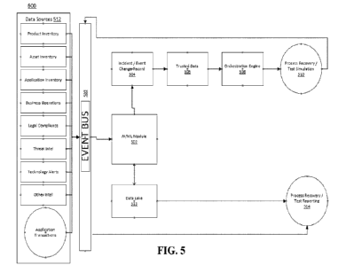
[00120] The UCI mapping rule for CSI reporting is shown in FIG. 5. When the
network-side device configures beam reporting as group-based beam reporting,
the
quantity N=2 of beam pairs that can be simultaneously received is reported,
each beam
pair includes two CRIs, and a quantity of CMRs of layer 1 measurement values
corresponding to the two CRIs is 2. CRI #1 and CRI #2 are a pair of beams that
can be
simultaneously received, and an L 1 -RSRP value (that is, a layer 1
measurement value)
corresponding to CRI #1 is largest among the four CRIs. Therefore, this value
is
arranged on top of the measurement values, and can be directly quantized and
mapped.
CRI #3 and CRI #4 are another pair of beams that can be simultaneously
received, and
their L 1 -RSRP value differences are differentially reported in descending
order.
CA 03213940 2023- 9- 28
[00121] It should be noted that, in the foregoing example 4, when the terminal
encodes the target CSI measurement resource indicators in a manner of joint
encoding
and mapping, the terminal needs to report only two CSI measurement resource
indicators, and the layer 1 measurement values can be reported as 2 or 4.
[00122] Optionally, in this embodiment of this application, in a case that the
beam
reporting type is group-based and non-group-based hybrid beam reporting, the
preset
mapping rule includes either of the following:
a third rule; and
a fourth rule, where
the third rule includes: a second CSI measurement resource indicator is
arranged in a first position, and an arrangement order of the N pairs of first
beams and
the M second beams is determined based on a beam reporting type of a beam
corresponding to the second CSI measurement resource indicator, where the
second
CSI measurement resource indicator is a CSI measurement resource indicator
corresponding to a beam whose layer 1 measurement value is largest among the N
pairs
of first beams and the M second beams; and
the fourth rule includes: if the third rule is satisfied, the layer 1
measurement
value corresponding to the second CSI measurement resource indicator is
mapped, and
layer 1 measurement values of remaining beams are mapped based on differences
between the layer 1 measurement value corresponding to the second CSI
measurement
resource indicator and the layer 1 measurement values of the remaining beams.
[00123] For example, in a case that the preset mapping rule is the third rule,
an
arrangement manner of the CSI measurement resource indicators is shown in
example
7.
[00124] Example 7: When the beam reporting type is non-group-based and group-
based hybrid beam reporting, the CSI measurement resource indicators include
CRI #1,
CRI #2, CRI #3, and CRI #4. Assuming that the terminal supports reporting of
one pair
of beams that can be simultaneously received (that is, N=1) and two beams
whose L 1 -
RSRPs (that is, layer 1 measurement values) are highest (each beam is
associated with
one CORESETPoolIndex, and M=2), if a beam reporting type of a CRI (a CSI
31
CA 03213940 2023- 9- 28
measurement resource indicator) corresponding to RSRP #1 (that is, the largest
layer 1
measurement value) is non-group-based beam reporting, the terminal arranges
CRI #1
corresponding to RSRP #1 and CRI #2 corresponding to RSRP #2 whose measurement
value is the second largest on top of all measurement resource indicators in
the CSI
report, and CRI #3 and CRI #4 are paired and arranged after CRI #2 in
sequence.
Conversely, the terminal needs to place the reported CRI #3 and CRI #4 on top
of all
measurement resource indicators based on the two beam reporting types
respectively,
and place CRI #1 and CRI #2 after CRI #4.
[00125] For example, when the preset mapping rule is the fourth rule, an
arrangement manner of layer 1 measurement values corresponding to the target
CSI
measurement resource indicators is as follows: the largest layer 1 measurement
value
(that is, an Li -RSRP value or an Ll-SINR value), that is, RSRP #1, is
directly quantized
and mapped, and is arranged in a first position in a layer 1 measurement value
sequence;
and remaining layer 1 measurement values are differentiated from the largest
value of
the layer 1 measurement values and then quantized and mapped, and a specific
arrangement order corresponds to the arrangement order of corresponding CRIs
or
SSBRIs.
[00126] Example 8: When the network-side device configures beam reporting as
non-group-based beam reporting and supports reporting of four beams, the UCI
mapping rule for CSI reporting is shown in FIG. 6. CRI #1, CRI #2, CRI #3, and
CRI
#4 are four CMR identifiers with largest L 1 -RSRP values (measurement
values), and
the L 1 -RSRP value corresponding to CRI #1 is the largest among the four
CRIs.
Therefore, this value is arranged on top of the measurement values, and may be
directly
quantized and mapped. L 1 -RSRPs corresponding to CRI #2, CRI #3, and CRI #4
are
differentially reported.
[00127] It should be noted that when the CRIs are jointly encoded and mapped,
only
two CRIs need to be reported, but two or four L 1 -RSRP values need to be
reported.
[00128] Optionally, in this embodiment of this application, the terminal adds
a first
indicator field before an indicator field corresponding to a third CSI
measurement
resource indicator, or the terminal extends a second indicator field
corresponding to a
32
CA 03213940 2023- 9- 28
third CSI measurement resource indicator, where the first indicator field and
the second
indicator field are used to indicate the beam reporting type.
[00129] For example, the third CSI measurement resource indicator is either of
the
following: the second CSI measurement resource indicator; and all CSI
measurement
resource indicators in the N pairs of first beams and the M second beams.
[00130] In an example, in a case that the terminal adds the first indicator
field before
the indicator field corresponding to the third CSI measurement resource
indicator, the
terminal may add the first indicator field before each CSI measurement
resource
indicator, that is, add the first indicator field before all CSI measurement
resource
indicators in the N pairs of first beams and the M second beams; or the
terminal may
add the first indicator field before only the first CSI measurement resource
indicator,
that is, the terminal adds the first indicator field only before the second
CSI
measurement resource indicator. The first indicator field may be a field
occupying a 1-
bit resource.
[00131] In another example, in a case that the terminal extends the second
indicator
field corresponding to the third CSI measurement resource indicator, the
terminal may
extend the second indicator field in each CSI measurement resource, that is,
extend the
second indicator field in all CSI measurement resource indicators in the N
pairs of first
beams and the M second beams; or the terminal may extend the second indicator
field
in only the first CSI measurement resource indicator, that is, the terminal
adds the
second indicator field only before the second CSI measurement resource
indicator. The
second indicator field may be a field occupying a 1-bit resource.
[00132] In this way, the terminal indicates the beam reporting type by adding
an
indicator field to a CSI measurement resource indicator, so that the network-
side device
can obtain the beam reporting type through parsing after receiving the CSI
report
including the CSI measurement resource indicator, and parse the CSI report
according
to a mapping rule corresponding to the beam reporting type.
[00133] Optionally, in this embodiment of this application, in a case that the
beam
reporting type is determined by the terminal according to the preset rule of
the network-
33
CA 03213940 2023- 9- 28
side device, and that the beam reporting type is group-based beam reporting,
the preset
mapping rule includes:
[00134] the terminal arranges, in a first position, a first CSI measurement
resource
indicator corresponding to a beam whose layer 1 measurement value is largest
among
the N pairs of first beams, and sequentially arranges CSI measurement resource
indicators of remaining first beam pairs in a form of beam pairs, where the
remaining
first beam pairs include other beam pairs than a beam pair including the beam
whose
layer 1 measurement value is the largest among the N pairs of first beams.
[00135] For example, first beam pairs generated by the remaining first beam
pairs
satisfy a first relationship, and the first relationship is a fixed value
relationship between
layer 1 measurement values in the beam pairs.
[00136] For example, the foregoing fixed value relationship may be configured
in
advance or set by default by the network-side device and the terminal.
[00137] For example, the first beam pair may include one beam pair or a
plurality of
beam pairs. For example, when N is 6, the terminal pairs the six pairs of
beams, and
there are three beam pairs in total. The first beam in the first beam pair
corresponds to
the largest layer 1 measurement value, and the remaining beam pairs are the
remaining
first beam pairs, and there are two beam pairs in total. Further, in either of
the two beam
pairs, the measurement value of the first beam is greater than the measurement
value of
the second beam. To be specific, that the measurement value of the first beam
is greater
than the measurement value of the second beam means that there is a fixed
value
relationship.
[00138] Example 9: It is assumed that the CSI measurement resource indicators
include CRI #1, CRI #2, CRI #3, CRI #4, and that layer 1 measurement values
corresponding to the four CRIs. CRI #1 and CRI #2 constitute a beam pair that
can be
simultaneously received, and CRI #3 and CRI #4 constitute a beam pair that can
be
simultaneously received. CRI #1 is a CMR identifier corresponding to the
largest L 1 -
RSRP value, and an L 1 -RSRP value corresponding to CRI #3 is not less than an
L 1 -
RSRP value corresponding to CRI #4 (that is, the foregoing fixed value
relationship).
34
CA 03213940 2023- 9- 28
[00139] It may be understood that, in example 5 to example 9, CRI #1, CRI #2,
CRI
#3, and CRI #4 may alternatively be SSBRI #1, SSBRI #2, SSBRI #3, and SSBRI
#4.
The Ll -RSRP value may alternatively be an Ll-SINR value.
[00140] Further, the arrangement order of the layer 1 measurement values
corresponds to the arrangement order of the CSI measurement resource
indicators,
where the largest value of the layer 1 measurement values is directly
quantized and
mapped, and the remaining measurement values are differentiated from the
largest
value and then quantized and mapped. In this way, the terminal can reduce
resource
occupation overheads.
[00141] Further, after the terminal reports the information about the first
beams
according to the UCI mapping rule satisfying a first condition, and the
network-side
device receives the information about the first beams according to the UCI
mapping
rule satisfying the first condition, it can be known that the received beam
information
is reported according to group-based beam reporting, and can be used for mTRP
transmission.
[00142] Optionally, in this embodiment of this application, in a case that the
beam
reporting type is determined by the terminal according to the preset rule of
the network-
side device, and that the beam reporting type is non-group-based beam
reporting, the
preset mapping rule includes:
the terminal arranges, in a first position, a second CSI measurement resource
indicator corresponding to a beam whose layer 1 measurement value is largest
among
the M second beams, and sequentially arranges CSI measurement resource
indicators
of remaining second beams, where the remaining second beams are other beams
than
the beam whose layer 1 measurement value is the largest among the M second
beams;
and
the terminal generates second beam pairs by pairing the second beams,
where
the second beam pairs satisfy a second condition, and the second condition
is: among the second beam pairs, there is at least one pair with a fixed value
relationship
CA 03213940 2023- 9- 28
between layer 1 measurement values corresponding to CSI measurement resource
indicators.
[00143] For example, for the predetermined condition, refer to the foregoing
description. Details are not described herein again.
[00144] For example, the CSI measurement resource indicator of the first beam
in
the first beam pair is a CMR identifier with the largest layer 1 measurement
value, the
largest value of the layer 1 measurement values is directly mapped, and the
remaining
layer 1 measurement values are differentiated from the largest layer 1
measurement
value and then quantized and mapped.
[00145] In an example, in the information about the second beams, after the
second
beam pairs are generated by pairing the second beams, a first beam pair in the
second
beam pairs includes: the second CSI measurement resource indicator and a CSI
measurement resource indicator in a second position after the CSI measurement
resource indicators are sorted, and among the CSI measurement resource
indicators
corresponding to the second beams, there is at least one group of CSI
measurement
resource indicators satisfying that a layer 1 measurement value corresponding
to a first
CSI measurement resource indicator in the group is less than a layer 1
measurement
value corresponding to a second CSI measurement resource indicator in the
group.
Further, a mapping sequence of all layer 1 measurement values corresponds to
CSI
measurement resource indicators of the layer 1 measurement values.
[00146] For example, the CSI measurement resource indicators in the second
beam
pairs may correspond to different CSI measurement resource settings, or CSI
measurement resource sets, or CSI measurement resource subsets.
[00147] Further, after the terminal reports the information about the first
beams
according to the UCI mapping rule satisfying the second condition, and the
network-
side device receives the information about the first beams according to the
UCI
mapping rule satisfying the second condition, it can be known that the
received beam
information is reported according to non-group-based beam reporting, and can
be used
for sTRP transmission.
36
CA 03213940 2023- 9- 28
100148] Optionally, in this embodiment of this application, in a case that the
beam
reporting type is determined by the terminal according to the preset rule of
the network-
side device, and that the beam reporting type is group-based and non-group-
based
hybrid beam reporting, the preset mapping rule includes:
the terminal generates T pairs of second beams by pairing the M second
beams, and arranges the N pairs of first beams before the T pairs of second
beams,
where
the N pairs of first beams and the T pairs of second beams satisfy a third
condition, and the third condition includes:
layer 1 measurement values corresponding to CSI measurement resource
indicators arranged in first positions in each of the N pairs of first beams
are sorted in
descending order, layer 1 measurement values corresponding to CSI measurement
resource indicators corresponding to each pair of first beams are sorted in
descending
order, and the layer 1 measurement values corresponding to the CSI measurement
resource indicators arranged in the first positions in each of the N pairs of
first beams
are non-differentially mapped; and
layer 1 measurement values corresponding to CSI measurement resource
indicators arranged in first positions in each of the T pairs of second beams
are sorted
in descending order, layer 1 measurement values corresponding to CSI
measurement
resource indicators corresponding to each pair of second beams are sorted in
descending
order, and the layer 1 measurement values corresponding to the CSI measurement
resource indicators arranged in the first positions in each of the T pairs of
second beams
are non-differentially mapped.
[00149] For example, the third relationship is: the terminal sorts the N pairs
of first
beams in descending order based on layer 1 measurement values corresponding to
CSI
measurement resource indicators arranged in first positions in each pair of
first beams,
and sorts CSI measurement resource indicators corresponding to each pair of
first
beams in descending order based on layer 1 measurement values corresponding to
the
CSI measurement resource indicators, and the layer 1 measurement values
37
CA 03213940 2023- 9- 28
corresponding to the CSI measurement resource indicators arranged in the first
positions in each of the N pairs of first beams are non-differentially mapped;
and
then the terminal further sorts the T pairs of second beams in descending
order based on layer 1 measurement values corresponding to CSI measurement
resource
indicators arranged in first positions in each pair of second beams, and sorts
CSI
measurement resource indicators corresponding to each pair of second beams in
descending order based on layer 1 measurement values corresponding to the CSI
measurement resource indicators, and the CSI measurement resource indicators
arranged in the first positions in each of the T pairs of second beams are non-
differentially mapped.
100150] For example, two CSI measurement resource indicators in each of the N
pairs of first beams and the T pairs of second beams may correspond to
different CSI
measurement resource settings, or CSI measurement resource sets, or CSI
measurement
resource subsets.
[00151] For example, the layer 1 measurement values corresponding to the CSI
measurement resource indicators of the second beams in each of the N pairs of
first
beams and the T pairs of second beams may be non-differentially mapped, or the
layer
1 measurement values corresponding to the CSI measurement resource indicators
of the
first beams are differentially mapped. Resource occupation overheads can be
reduced
by setting the layer 1 measurement value corresponding to the CSI measurement
resource indicator of the second beam to a difference between the layer 1
measurement
value corresponding to the CSI measurement resource indicator of the second
beam and
the layer 1 measurement value corresponding to the CSI measurement resource
indicator of the first beam.
[00152] Further, after the terminal reports the information about the first
beams and
the information about the second beams according to the foregoing UCI mapping
rule
satisfying the third condition, and the network-side device receives the
information
about the first beams and the information about the second beams according to
the UCI
mapping rule satisfying the third condition, it can be known that the received
beam
38
CA 03213940 2023- 9- 28
information is reported according to group-based and non-group-based hybrid
beam
reporting.
[00153] Optionally, if inversion occurs (that is, at least one layer 1
measurement
value corresponding to a first measurement resource indicator in a beam pair
arranged
in a rear position is greater than a layer 1 measurement value corresponding
to a first
measurement resource indicator of a beam pair arranged in a front position),
it can be
known that the received beam information is reported according to hybrid beam
reporting, and a CRI or an SSBRI before the position in which the inversion
occurs for
the first time is group-based reported and can be used for mTRP transmission,
while a
CRI or an SSBRI after this position is non-group-based reported and can be
used for
sTRP transmission.
[00154] FIG. 7 is a schematic flowchart of a channel state information CSI
report
mapping method according to an embodiment of this application. As shown in
FIG. 7,
the method is applied to a network-side device, and the channel state
information CSI
report mapping method may include step 301 and step 302.
[00155] Step 301: A network-side device receives a CSI report reported by a
terminal.
[00156] Step 302: The network-side device parses the CSI report based on a
beam
reporting type.
[00157] In this embodiment of this application, the CSI report includes at
least one
of the following: information for indicating the beam reporting type and
information
about target beams; the target beams include at least one of the following: N
pairs of
first beams that can be simultaneously received by the terminal, and M second
beams
whose measurement values satisfy a predetermined condition, where N is a
positive
integer greater than or equal to 1, and M is a positive integer; and the beam
reporting
type is configured by the network-side device for the terminal, or determined
by the
terminal according to a preset rule of the network-side device.
[00158] In this embodiment of this application, the beam reporting type
includes at
least one of the following: group-based beam reporting, non-group-based beam
reporting, and group-based and non-group-based hybrid beam reporting.
39
CA 03213940 2023- 9- 28
100159] In this embodiment of this application, the network-side device may
parse
the CSI report based on the beam reporting type after receiving the CSI report
reported
by the terminal. In the foregoing process, the network-side device may receive
CSI
reports provided by the terminal in a plurality of beam reporting manners, and
flexibly
perform parsing in a parsing manner corresponding to a corresponding preset
mapping
manner.
[00160] Optionally, in this embodiment of this application, before step 301,
the
channel state information CSI report mapping method provided in this
embodiment of
this application may further include the following step 303 or step 304.
[00161] Step 303: The network-side device configures the beam reporting type
in a
CSI report configuration.
[00162] Step 304: The network-side device configures the beam reporting type
by
presetting the preset rule for the terminal, where the preset rule corresponds
to the beam
reporting type.
[00163] Optionally, in this embodiment of this application, in a case that the
network-side device does not configure the beam reporting type in the CSI
report
configuration, before step 302, the channel state information CSI report
mapping
method provided in this embodiment of this application may further include the
following step 305.
[00164] Step 305: The network-side device determines the beam reporting type
of
the CSI report in a preset manner.
[00165] For example, the preset manner includes any one of the following:
querying the beam reporting type indicated by a target field;
querying a value relationship between a measurement value of a CSI
measurement resource and a target measurement threshold in the CSI report,
where the
value relationship is used to indicate the beam reporting type; and
querying whether the N pairs of first beams and/or the M second beams
satisfy a first condition, a second condition, or a third condition.
100166] Optionally, in this embodiment of this application, the
first condition is: first
beam pairs generated by remaining first beam pairs satisfy a first
relationship, and the
CA 03213940 2023- 9- 28
first relationship is a fixed value relationship between layer 1 measurement
values in
the remaining first beam pairs, where the remaining first beam pairs include
other beam
pairs than a beam pair including a beam whose layer 1 measurement value is
largest
among the N pairs of first beams;
the second condition is: among second beam pairs, there is at least one pair
with a fixed value relationship between layer 1 measurement values
corresponding to
CSI measurement resource indicators, and among second beam pairs, there is at
least
one pair with a fixed value relationship between layer 1 measurement values
corresponding to CSI measurement resource indicators, where the second beam
pairs
are beam pairs generated by the terminal by pairing the second beams; and
the third condition includes:
the N pairs of first beams are arranged before T pairs of second beams;
layer 1 measurement values corresponding to CSI measurement resource
indicators arranged in first positions in each of the N pairs of first beams
are sorted in
descending order, layer 1 measurement values corresponding to CSI measurement
resource indicators corresponding to each pair of first beams are sorted in
descending
order, and the layer 1 measurement values corresponding to the CSI measurement
resource indicators arranged in the first positions in each of the N pairs of
first beams
are non-differentially mapped; and
layer 1 measurement values corresponding to CSI measurement resource
indicators arranged in first positions in each of the T pairs of second beams
are sorted
in descending order, layer 1 measurement values corresponding to CSI
measurement
resource indicators corresponding to each pair of second beams are sorted in
descending
order, and the layer 1 measurement values corresponding to the CSI measurement
resource indicators arranged in the first positions in each of the T pairs of
second beams
are non-differentially mapped.
[00167] For example, layer 1 measurement values corresponding to CSI
measurement resource indicators arranged in first positions in each of the N
pairs of
first beams are sorted in descending order, CSI measurement resource
indicators
corresponding to each pair of first beams are sorted in descending order of
layer 1
41
CA 03213940 2023- 9- 28
measurement values corresponding to the CSI measurement resource indicators,
and
the layer 1 measurement values corresponding to the CSI measurement resource
indicators arranged in the first positions in each of the N pairs of first
beams are non-
differentially mapped; and the T pairs of second beams are sorted in
descending order
based on layer 1 measurement values corresponding to CSI measurement resource
indicators arranged in first positions in each pair of second beams, CSI
measurement
resource indicators corresponding to each pair of second beams are sorted in
descending
order based on layer 1 measurement values corresponding to the CSI measurement
resource indicators, and the CSI measurement resource indicators arranged in
the first
positions in each of the T pairs of second beams are non-differentially
mapped.
[00168] Optionally, in this embodiment of this application, in a case that the
preset
manner is querying whether the N pairs of first beams and/or the M second
beams
satisfy the first condition, the second condition, or the third condition,
that the network-
side device determines the beam reporting type of the CSI report in a preset
manner
includes:
if the network-side device determines that measurement values
corresponding to target CSI measurement resource indicators in the information
about
the target beams satisfy the first condition, determining that the beam
reporting type is
group-based beam reporting;
if the network-side device determines that measurement values
corresponding to target CSI measurement resource indicators in the information
about
the target beams satisfy the second condition, determining that the beam
reporting type
is non-group-based beam reporting; or
if the network-side device determines that measurement values
corresponding to target CSI measurement resource indicators in the information
about
the target beams satisfy the third condition, determining that the beam
reporting type
includes group-based beam reporting and non-group-based beam reporting.
[00169] For example, in a case that the network-side device determines that
the beam
reporting type is group-based beam reporting, the network-side device
subsequently
communicates with the terminal through mTRP transmission.
42
CA 03213940 2023- 9- 28
[00170] For example, in a case that the network-side device determines that
the beam
reporting type is non-group-based beam reporting, the network-side device
subsequently communicates with the terminal through sTRP transmission.
[00171] For example, in a case that the network-side device determines that
the beam
reporting type is group-based and non-group-based hybrid beam reporting, the
network-
side device uses a part of measurement resource indicators corresponding to
the group-
based reporting hypothesis type for mTRP transmission, and uses a part of
measurement
resource indicators corresponding to the non-group-based reporting hypothesis
type for
sTRP transmission.
[00172] It should be noted that after the network-side device receives a
PUCCH/PUSCH carrying UCI, the network-side device combines information about
two adjacent beams in the UCI. If inversion occurs (that is, at least one
layer 1
measurement value corresponding to a first measurement resource indicator in a
beam
pair arranged in a rear position is greater than a layer 1 measurement value
corresponding to a first measurement resource indicator of a beam pair
arranged in a
front position), it can be known that the received beam information is
reported based
on the hybrid beam reporting type, and a CRI or an SSBRI before the position
in which
the inversion occurs for the first time is group-based reported and can be
used for mTRP
transmission, while a CRI or an SSBRI after this position is non-group-based
reported
and can be used for sTRP transmission.
[00173] It should be noted that the channel state information CSI report
mapping
method provided in this embodiment of this application may be performed by a
channel
state information CSI report mapping apparatus, or a control module for
performing the
channel state information CSI report mapping method in the channel state
information
CSI report mapping apparatus. A channel state information CSI report mapping
apparatus provided in an embodiment of this application is described by
assuming that
the channel state information CSI report mapping method is performed by the
channel
state information CSI report mapping apparatus in this embodiment of this
application.
[00174] An embodiment of this application provides a channel state information
CSI
report mapping apparatus. As shown in FIG. 8, the channel state information
CSI report
43
CA 03213940 2023- 9- 28
mapping apparatus 400 includes a feedback module 401. The feedback module 401
is
configured to feed back X CSI reports to a network-side device through a
target channel
according to a preset mapping rule, where the CSI report includes at least one
of the
following: information for indicating a beam reporting type and information
about
target beams; the target beams include at least one of the following: N pairs
of first
beams that can be simultaneously received by a terminal, and M second beams
whose
measurement values satisfy a predetermined condition, where N is a positive
integer
greater than or equal to 1, and X and M are positive integers; and the preset
mapping
rule is a mapping rule that matches the beam reporting type.
1001751 The channel state information CSI report mapping apparatus provided in
this embodiment of this application maps the X CSI reports (the CSI report
includes the
information for indicating the beam reporting type and/or the information
about the
target beams) to UCI, and then feeds back the X CSI reports to the network-
side device
through the target channel (for example, a physical uplink control channel
(Physical
Uplink Control Channel, PUCCH) or a physical uplink shared channel (Physical
Uplink
Shared Channel, PUSCH)), so that the network-side device performs
communication
and transmission with the channel state information CSI report mapping
apparatus
based on a mapping result reported by the channel state information CSI report
mapping
apparatus. In the foregoing process, because the target beams include the N
pairs of first
beams that can be simultaneously received by the terminal, (N is a positive
integer
greater than 1), and/or the M second beams whose measurement values satisfy
the
predetermined condition (M is a positive integer), in a case that the beam
reporting type
is group-based beam reporting, the method provided in the embodiments of this
application can enable the terminal to simultaneously report a plurality of
pairs of
beams, instead of reporting only one pair of beams.
1001761 Optionally, in this embodiment of this application, the beam reporting
type
includes any one of the following: group-based beam reporting, non-group-based
beam
reporting, and group-based and non-group-based hybrid beam reporting; and the
beam
reporting type is configured by the network-side device for the terminal, or
determined
by the terminal according to a preset rule of the network-side device.
44
CA 03213940 2023- 9- 28
[00177] Optionally, in this embodiment of this application, the information
about the
target beams includes at least one of the following: target CSI measurement
resource
indicators and measurement values of target CSI measurement resources; and the
target
CSI measurement resource indicators are CSI reference signal resource
indicators CRIs
or system synchronization block resource indicators SSBRIs, and the
measurement
values of the target CSI measurement resources are layer 1 measurement values.
[00178] Optionally, in this embodiment of this application, values of M and N
can
be configured by the network-side device by using RRC signaling, or configured
by
using RRC signaling, and selected, determined, and modified by using a MAC-CE.
[00179] Optionally, in this embodiment of this application, when the beam
reporting
type is configured by the network-side device for the terminal, the beam
reporting type
may be modified by the network-side device by using a MAC-CE.
[00180] Optionally, in this embodiment of this application, in a case that the
target
CSI report includes the target CSI measurement resource indicators, the
apparatus 400
further includes an encoding module 402, where the encoding module is
configured to
encode the target CSI measurement resource indicators based on a preset
encoding
mode, where the target CSI measurement resource indicators include all target
CSI
measurement resource indicators or a part of target CSI measurement resource
indicators; and the preset encoding mode includes at least one of the
following:
performing encoding based on a quantity of channel measurement resources CMRs
configured in a CSI measurement resource setting; performing encoding based on
a
quantity of CMRs configured in a CSI measurement resource set; performing
encoding
based on a quantity of CMRs configured in a CSI measurement resource subset in
the
CSI measurement resource set; and performing joint encoding based on CMR
resources.
[00181] Optionally, in this embodiment of this application, in a case that the
beam
reporting type is configured by the network-side device, or determined by the
terminal
according to the preset rule of the network-side device, the apparatus 400
further
includes a selection module 403, where if the beam reporting type is group-
based beam
reporting, the selection module 403 is configured to select to report
information about
the N pairs of first beams that can be simultaneously received by the
terminal, where
CA 03213940 2023- 9- 28
target CSI measurement resource indicators in information about each pair of
first
beams correspond to different CSI measurement resources; if the beam reporting
type
is non-group-based beam reporting, the selection module 403 is further
configured to
select to report information about the M second beams that satisfy the
predetermined
condition; or if the beam reporting type includes group-based and non-group-
based
hybrid beam reporting, the selection module 403 is further configured to
select to report
information about Q pairs of first beams and information about W second beams,
where
Q is less than or equal to N, W is less than or equal to M, Q and W can be
configured
by the network-side device or set according to a preset rule, and Q and W are
positive
integers; and the CSI measurement resources include any one of the following:
a CSI
measurement resource setting, a CSI measurement resource set, and a CSI
measurement
resource subset.
[00182] Optionally, in this embodiment of this application, in a case that the
beam
reporting type is determined by the terminal according to the preset rule of
the network-
side device, the beam reporting type can be indicated in either of the
following manners:
the beam reporting type is indicated by a target field in the CSI report; and
the beam
reporting type is indicated based on a value relationship between a
measurement value
of a CSI measurement resource and a target measurement threshold in the CSI
report,
where the target measurement threshold is configured by the network-side
device, or
preset by the network-side device and the terminal.
[00183] Optionally, in this embodiment of this application, in a case that the
beam
reporting type is configured by the network-side device for the terminal, or
determined
by the terminal according to the preset rule of the network-side device, in a
case that
the beam reporting type is group-based beam reporting, the preset mapping rule
includes either of the following: a first rule; and a second rule, where the
first rule
includes: a first CSI measurement resource indicator is arranged in a first
position, and
CSI measurement resource indicators of remaining beams are sequentially
arranged in
a form of beam pairs, where the first CSI measurement resource indicator is a
measurement resource indicator corresponding to a beam whose layer 1
measurement
value is largest among the N pairs of first beams; and the second rule
includes: if the
46
CA 03213940 2023- 9- 28
first rule is satisfied, the layer 1 measurement value corresponding to the
first CSI
measurement resource indicator is mapped, and layer 1 measurement values of
the
remaining beams are mapped based on differences between the layer 1
measurement
value corresponding to the first CSI measurement resource indicator and the
layer 1
measurement values of the remaining beams.
100184] Optionally, in this embodiment of this application, in a case that the
beam
reporting type is group-based and non-group-based hybrid beam reporting, the
preset
mapping rule includes either of the following: a third rule; and a fourth
rule, where the
third rule includes: a second CSI measurement resource indicator is arranged
in a first
position, and an arrangement order of the N pairs of first beams and the M
second beams
is determined based on a beam reporting type of a beam corresponding to the
second
CSI measurement resource indicator, where the second CSI measurement resource
indicator is a CSI measurement resource indicator corresponding to a beam
whose layer
1 measurement value is largest among the N pairs of first beams and the M
second
beams; and the fourth rule includes: if the third rule is satisfied, the layer
1 measurement
value corresponding to the second CSI measurement resource indicator is
mapped, and
layer 1 measurement values of remaining beams are mapped based on differences
between the layer 1 measurement value corresponding to the second CSI
measurement
resource indicator and the layer 1 measurement values of the remaining beams.
[00185] Optionally, in this embodiment of this application, the apparatus 400
further
includes an addition module 404 and an extension module 405, where the
addition
module 404 is configured to add a first indicator field before an indicator
field
corresponding to a third CSI measurement resource indicator; or the extension
module
405 is configured to extend a second indicator field corresponding to a third
CSI
measurement resource indicator, where the first indicator field and the second
indicator
field are used to indicate the beam reporting type, where the third CSI
measurement
resource indicator is either of the following: the second CSI measurement
resource
indicator; and all CSI measurement resource indicators in the N pairs of first
beams and
the M second beams.
47
CA 03213940 2023- 9- 28
[00186] Optionally, in this embodiment of this application, in a case that the
beam
reporting type is determined by the terminal according to the preset rule of
the network-
side device, and that the beam reporting type is group-based beam reporting,
the preset
mapping rule includes: a first CSI measurement resource indicator
corresponding to a
beam whose layer 1 measurement value is largest among the N pairs of first
beams is
arranged in a first position, and CSI measurement resource indicators of
remaining first
beam pairs are sequentially arranged in a form of beam pairs, where the
remaining first
beam pairs include other beam pairs than a beam pair including the beam whose
layer
1 measurement value is the largest among the N pairs of first beams, where
first beam
pairs generated by the remaining first beam pairs satisfy a first
relationship, and the first
relationship is a fixed value relationship between layer 1 measurement values
in each
of the first beam pairs.
[00187] Optionally, in this embodiment of this application, in a case that the
beam
reporting type is determined by the terminal according to the preset rule of
the network-
side device, and that the beam reporting type is non-group-based beam
reporting, the
preset mapping rule includes: a second CSI measurement resource indicator
corresponding to a beam whose layer 1 measurement value is largest among the M
second beams is arranged in a first position, and CSI measurement resource
indicators
of remaining second beams are sequentially arranged, where the remaining
second
beams are other beams than the beam whose layer 1 measurement value is the
largest
among the M second beams; and second beam pairs are generated by pairing the
second
beams, where the second beam pairs satisfy a second condition, and the second
condition is: among the second beam pairs, there is at least one pair with a
fixed value
relationship between layer 1 measurement values corresponding to CSI
measurement
resource indicators.
[00188] Optionally, in this embodiment of this application, in a case that the
beam
reporting type is determined by the terminal according to the preset rule of
the network-
side device, and that the beam reporting type is group-based and non-group-
based
hybrid beam reporting, the preset mapping rule includes: T pairs of second
beams are
generated by pairing the M second beams, where the N pairs of first beams and
the T
48
CA 03213940 2023- 9- 28
pairs of second beams satisfy a third condition, and the third condition
includes: the N
pairs of first beams are arranged before the T pairs of second beams; layer 1
measurement values corresponding to CS! measurement resource indicators
arranged
in first positions in each of the N pairs of first beams are sorted in
descending order,
layer 1 measurement values corresponding to CSI measurement resource
indicators
corresponding to each pair of first beams are sorted in descending order, and
the layer
1 measurement values corresponding to the CSI measurement resource indicators
arranged in the first positions in each of the N pairs of first beams are non-
differentially
mapped; and layer 1 measurement values corresponding to CSI measurement
resource
indicators arranged in first positions in each of the T pairs of second beams
are sorted
in descending order, layer 1 measurement values corresponding to CSI
measurement
resource indicators corresponding to each pair of second beams are sorted in
descending
order, and the layer 1 measurement values corresponding to the CSI measurement
resource indicators arranged in the first positions in each of the T pairs of
second beams
are non-differentially mapped.
100189] An embodiment of this application provides a channel state information
CSI
report mapping apparatus. As shown in FIG. 9, the channel state information
CSI report
mapping apparatus 500 includes a receiving module 501 and a parsing module
502. The
receiving module 501 is configured to receive a CSI report reported by a
terminal. The
parsing module 502 is configured to parse, based on a beam reporting type, the
CSI
report received by the receiving module 501, where the CSI report includes at
least one
of the following: information for indicating the beam reporting type and
information
about target beams; the target beams include at least one of the following: N
pairs of
first beams that can be simultaneously received by the terminal, and M second
beams
whose measurement values satisfy a predetermined condition, where N is a
positive
integer greater than 1, and M is a positive integer; and the beam reporting
type is
configured by a network-side device for the terminal, or determined by the
terminal
according to a preset rule of a network-side device; and the beam reporting
type
includes at least one of the following: group-based beam reporting, non-group-
based
beam reporting, and group-based and non-group-based hybrid beam reporting.
49
CA 03213940 2023- 9- 28
[00190] The channel state information CSI report mapping apparatus provided in
this embodiment of this application may parse the CSI report based on the beam
reporting type after receiving the CSI report reported by the terminal. In the
foregoing
process, the channel state information CSI report mapping apparatus may
receive CSI
reports provided by the terminal in a plurality of beam reporting manners, and
flexibly
perform parsing in a parsing manner corresponding to a corresponding preset
mapping
manner.
[00191] Optionally, in this embodiment of this application, the apparatus 500
further
includes a reporting module 503 and a configuration module 504, where the
reporting
module 503 is configured to configure the beam reporting type in a CSI report
configuration; or the configuration module 504 is configured to configure the
beam
reporting type by presetting the preset rule for the terminal, where the
preset rule
corresponds to the beam reporting type.
[00192] Optionally, in this embodiment of this application, in a case that the
network-side device does not configure the beam reporting type in a CSI report
configuration, the apparatus further includes a determining module 505, where
the
determining module is configured to determine the beam reporting type of the
CSI
report in a preset manner, where the preset manner includes any one of the
following:
querying the beam reporting type indicated by a target field; querying a value
relationship between a measurement value of a CSI measurement resource and a
target
measurement threshold in the CSI report, where the value relationship is used
to
indicate the beam reporting type; and querying whether the N pairs of first
beams and/or
the M second beams satisfy a first relationship, a second relationship, or a
third
relationship.
[00193] Optionally, in this embodiment of this application, the first
condition is a
fixed value relationship between layer 1 measurement values in each of first
beam pairs
of remaining first beam pairs, where the remaining first beam pairs include
other beam
pairs than a beam pair of a beam whose layer 1 measurement value is largest
among the
N pairs of first beams; the second condition is: among second beam pairs,
there is at
least one pair with a fixed value relationship between layer 1 measurement
values
CA 03213940 2023- 9- 28
corresponding to CSI measurement resource indicators, and among second beam
pairs,
there is at least one pair with a fixed value relationship between layer 1
measurement
values corresponding to CSI measurement resource indicators, where the second
beam
pairs are beam pairs generated by the terminal by pairing the second beams;
and the
third condition includes: layer 1 measurement values corresponding to CSI
measurement resource indicators arranged in first positions in each of the N
pairs of
first beams are sorted in descending order, and layer 1 measurement values
corresponding to CSI measurement resource indicators corresponding to each
pair of
first beams are sorted in descending order; and layer 1 measurement values
corresponding to CSI measurement resource indicators arranged in first
positions in
each of T pairs of second beams are sorted in descending order, and layer 1
measurement values corresponding to CSI measurement resource indicators
corresponding to each pair of second beams are sorted in descending order.
[00194] Optionally, in this embodiment of this application, in a case that the
preset
manner is querying whether the N pairs of first beams and/or the M second
beams
satisfy the first condition, the second condition, or the third condition, the
determining
module 505 is specifically configured to determine that the beam reporting
type is
group-based beam reporting if it is determined that measurement values
corresponding
to target CSI measurement resource indicators in the information about the
target beams
satisfy the first condition; the determining module 505 is specifically
configured to
determine that the beam reporting type is non-group-based beam reporting if it
is
determined that measurement values corresponding to target CSI measurement
resource
indicators in the information about the target beams satisfy the second
condition; or the
determining module 505 is specifically configured to determine that the beam
reporting
type includes group-based beam reporting and non-group-based beam reporting if
it is
determined that measurement values corresponding to target CSI measurement
resource
indicators in the information about the target beams satisfy the third
condition.
[00195] The channel state information CSI report mapping apparatus in this
embodiment of this application may be an apparatus, or an apparatus or an
electronic
device with an operating system, or may be a component, an integrated circuit,
or a chip
51
CA 03213940 2023- 9- 28
in a terminal. The apparatus or the electronic device may be a mobile
terminal, or may
be a nonmobile terminal. For example, the mobile terminal may include but is
not
limited to the foregoing illustrated type of the terminal 11. The nonmobile
terminal may
be a server, a network attached storage (Network Attached Storage, NAS), a
personal
computer (personal computer, PC), a television (television, TV), a teller
machine, a
self-service machine, or the like. This is not specifically limited in this
embodiment of
this application.
[00196] The channel state information CSI report mapping apparatus provided in
this embodiment of this application can implement each process implemented by
the
method embodiments in FIG. 1 to FIG. 7, with the same technical effect
achieved. To
avoid repetition, details are not described herein again.
[00197] Optionally, as shown in FIG. 10, an embodiment of this application
further
provides a communications device 600, including a processor 601, a memory 602,
and
a program or instructions stored in the memory 602 and capable of running on
the
processor 601. For example, when the communications device 600 is a terminal,
and
the program or instructions are executed by the processor 601, each process of
the
foregoing embodiment of the channel state information CSI report mapping
method is
implemented, with the same technical effect achieved. When the communications
device 600 is a network-side device, and the program or instructions are
executed by
the processor 601, each process of the foregoing embodiment of the channel
state
information CSI report mapping method is implemented, with the same technical
effect
achieved. To avoid repetition, details are not described herein again.
[00198] An embodiment of this application further provides a terminal,
including a
processor and a communications interface, where the communications interface
is
configured to feed back X CSI reports to a network-side device through a
target channel
according to a preset mapping rule. This terminal embodiment corresponds to
the
foregoing terminal-side method embodiment, and each implementation process and
implementation of the foregoing method embodiment can be applied to this
terminal
embodiment, with the same technical effect achieved. Specifically, FIG. 11 is
a
52
CA 03213940 2023- 9- 28
schematic diagram of a hardware structure of a terminal for implementing an
embodiment of this application.
[00199] The terminal 100 includes but is not limited to at least some
components
such as a radio frequency unit 101, a network module 102, an audio output unit
103, an
input unit 104, a sensor 105, a display unit 106, a user input unit 107, an
interface unit
108, a memory 109, and a processor 110.
[00200] A person skilled in the art may understand that the terminal 100 may
further
include a power supply (for example, a battery) supplying power to all
components.
The power supply may be logically connected to the processor 110 through a
power
management system. In this way, functions such as charge management, discharge
management, and power consumption management are implemented by using the
power management system. The terminal structure shown in FIG. 11 does not
constitute
a limitation on the terminal. The terminal may include more or fewer
components than
those shown in the figure, or some components are combined, or component
arrangements are different. Details are not described herein again.
[00201] It should be understood that, in this embodiment of this application,
the input
unit 104 may include a graphics processing unit (Graphics Processing Unit,
GPU) 1041
and a microphone 1042. The graphics processing unit 1041 processes image data
of a
still picture or video obtained by an image capture apparatus (such as a
camera) in a
video capture mode or an image capture mode. The display unit 106 may include
a
display panel 1061, and the display panel 1061 may be configured in a form of
a liquid
crystal display, an organic light-emitting diode, or the like. The user input
unit 107
includes a touch panel 1071 and other input devices 1072. The touch panel 1071
is also
referred to as a touchscreen. The touch panel 1071 may include two parts: a
touch
detection apparatus and a touch controller. The other input devices 1072 may
include
but are not limited to a physical keyboard, a function key (such as a volume
control key
or a power key), a trackball, a mouse, and a joystick. Details are not
described herein
again.
1002021 In this embodiment of this application, after receiving downlink data
from a
network-side device, the radio frequency unit 101 sends the downlink data to
the
53
CA 03213940 2023- 9- 28
processor 110 for processing, and in addition, sends uplink data to the
network-side
device. Generally, the radio frequency unit 101 includes but is not limited to
an antenna,
at least one amplifier, a transceiver, a coupler, a low noise amplifier, a
duplexer, and the
like.
[00203] The memory 109 may be configured to store software programs or
instructions and various data. The memory 109 may primarily include a program
or
instruction storage area and a data storage area. The program or instruction
storage area
may store an operating system, an application program or instructions (such as
an audio
play function and an image play function) required by at least one function,
and the like.
In addition, the memory 109 may include a high-speed random access memory, and
may further include a non-volatile memory. The non-volatile memory may be a
read-
only memory (Read-Only Memory, ROM), a programmable read-only memory
(Programmable ROM, PROM), an erasable programmable read-only memory
(Erasable PROM, EPROM), an electrically erasable programmable read-only memory
(Electrically EPROM, EEPROM), or a flash memory, for example, at least one
disk
storage device, a flash memory device, or another non-volatile solid-state
storage
device.
[00204] The processor 110 may include one or more processing units.
Optionally,
the processor 110 may integrate an application processor and a modem
processor. The
application processor mainly processes the operating system, a user interface,
an
application program, or an instruction. The modem processor mainly processes
wireless
communication. For example, the modem processor is a baseband processor. It
may be
understood that the modem processor may alternatively be not integrated in the
processor 110.
[00205] The radio frequency unit 101 is configured to feed back X CSI reports
to a
network-side device through a target channel according to a preset mapping
rule, where
the CSI report includes at least one of the following: information for
indicating a beam
reporting type and information about target beams; the target beams include at
least one
of the following: N pairs of first beams that can be simultaneously received
by the
terminal, and M second beams whose measurement values satisfy a predetermined
54
CA 03213940 2023- 9- 28
condition, where N is a positive integer greater than or equal to 1, and X and
M are
positive integers; and the preset mapping rule is a mapping rule that matches
the beam
reporting type.
[00206] The terminal provided in this embodiment of this application maps the
X
CSI reports (the CSI reports include the information for indicating the beam
reporting
type and/or the information about the target beams) to UCI according to the
preset
mapping rule matching the beam reporting type, and feeds back the X CSI
reports to
the network-side device through the target channel (for example, a physical
uplink
control channel (Physical Uplink Control Channel, PUCCH) or a physical uplink
shared
channel (Physical Uplink Shared Channel, PUSCH)), so that the network-side
device
performs communication and transmission with the terminal based on a mapping
result
reported by the terminal. In the foregoing process, because the target beams
include the
N pairs of first beams that can be simultaneously received by the terminal, (N
is a
positive integer greater than 1), and/or the M second beams whose measurement
values
satisfy the predetermined condition (M is a positive integer), in a case that
the beam
reporting type is group-based beam reporting, the method provided in this
embodiment
of this application can enable the terminal to simultaneously report a
plurality of pairs
of beams, instead of reporting only one pair of beams.
[00207] Optionally, the beam reporting type includes any one of the following:
group-based beam reporting, non-group-based beam reporting, and group-based
and
non-group-based hybrid beam reporting; and the beam reporting type is
configured by
the network-side device for the terminal, or determined by the terminal
according to a
preset rule of the network-side device.
[00208] Optionally, the information about the target beams includes at least
one of
the following: target CSI measurement resource indicators and measurement
values of
target CSI measurement resources; and the target CSI measurement resource
indicators
are CSI reference signal resource indicators CRIs or system synchronization
block
resource indicators SSBRIs, and the measurement values of the target CSI
measurement
resources are layer 1 measurement values.
CA 03213940 2023- 9- 28
[00209] Optionally, values of M and N can be configured by the network-side
device
by using RRC signaling, or configured by using RRC signaling, and selected,
determined, and modified by using a MAC-CE.
[002101 Optionally, when the beam reporting type is configured by the network-
side
device for the terminal, the beam reporting type can be modified by the
network-side
device by using a MAC-CE.
[00211] Optionally, in a case that the target CSI report includes the target
CSI
measurement resource indicators, the processor 110 is configured to encode the
target
CSI measurement resource indicators based on a preset encoding mode, where the
target CSI measurement resource indicators include all target CSI measurement
resource indicators or a part of target CSI measurement resource indicators;
and the
preset encoding mode includes at least one of the following: performing
encoding based
on a quantity of channel measurement resources CMRs configured in a CSI
measurement resource setting; performing encoding based on a quantity of CMRs
configured in a CSI measurement resource set; performing encoding based on a
quantity
of CMRs configured in a CSI measurement resource subset in the CSI measurement
resource set; and performing joint encoding based on CMR resources.
[00212] Optionally, in a case that the beam reporting type is configured by
the
network-side device, or determined by the terminal according to the preset
rule of the
network-side device, if the beam reporting type is group-based beam reporting,
the
radio frequency unit 101 is specifically configured to select to report
information about
the N pairs of first beams that can be simultaneously received by the
terminal, where
target CSI measurement resource indicators in information about each pair of
first
beams correspond to different CSI measurement resources; if the beam reporting
type
is non-group-based beam reporting, the radio frequency unit 101 is further
specifically
configured to select to report information about the M second beams that
satisfy the
predetermined condition; or if the beam reporting type includes group-based
and non-
group-based hybrid beam reporting, the radio frequency unit 101 is further
specifically
configured to select to report information about Q pairs of first beams and
information
about W second beams, where Q is less than or equal to N, W is less than or
equal to
56
CA 03213940 2023- 9- 28
M, Q and W can be configured by the network-side device or set according to a
preset
rule, and Q and W are positive integers; and the CSI measurement resources
include
any one of the following: a CSI measurement resource setting, a CSI
measurement
resource set, and a CSI measurement resource subset.
[00213] Optionally, in a case that the beam reporting type is determined by
the
terminal according to the preset rule of the network-side device, the beam
reporting
type can be indicated in either of the following manners: the beam reporting
type is
indicated by a target field in the CSI report; and the beam reporting type is
indicated
based on a value relationship between a measurement value of a CSI measurement
resource and a target measurement threshold in the CSI report, where the
target
measurement threshold is configured by the network-side device, or preset by
the
network-side device and the terminal.
[00214] Optionally, in a case that the beam reporting type is configured by
the
network-side device for the terminal, or determined by the terminal according
to the
preset rule of the network-side device, in a case that the beam reporting type
is group-
based beam reporting, the preset mapping rule includes either of the
following: a first
rule; and a second rule, where the first rule includes: a first CSI
measurement resource
indicator is arranged in a first position, and CSI measurement resource
indicators of
remaining beams are sequentially arranged in a form of beam pairs, where the
first CSI
measurement resource indicator is a measurement resource indicator
corresponding to
a beam whose layer 1 measurement value is largest among the N pairs of first
beams;
and the second rule includes: if the first rule is satisfied, the layer 1
measurement value
corresponding to the first CSI measurement resource indicator is mapped, and
layer 1
measurement values of the remaining beams are mapped based on differences
between
the layer 1 measurement value corresponding to the first CSI measurement
resource
indicator and the layer 1 measurement values of the remaining beams.
[00215] Optionally, in a case that the beam reporting type is group-based and
non-
group-based hybrid beam reporting, the preset mapping rule includes either of
the
following: a third rule; and a fourth rule, where the third rule includes: a
second CSI
measurement resource indicator is arranged in a first position, and an
arrangement order
57
CA 03213940 2023- 9- 28
of the N pairs of first beams and the M second beams is determined based on a
beam
reporting type of a beam corresponding to the second CSI measurement resource
indicator, where the second CSI measurement resource indicator is a CSI
measurement
resource indicator corresponding to a beam whose layer 1 measurement value
satisfies
the predetermined condition among the N pairs of first beams and the M second
beams;
and the fourth rule includes: if the third rule is satisfied, the layer 1
measurement value
corresponding to the second CSI measurement resource indicator is mapped, and
layer
1 measurement values of remaining beams are mapped based on differences
between
the layer 1 measurement value corresponding to the second CSI measurement
resource
indicator and the layer 1 measurement values of the remaining beams.
[00216] Optionally, the processor 110 is further configured to add a first
indicator
field before an indicator field corresponding to a third CSI measurement
resource
indicator; or the processor 110 is further configured to extend a second
indicator field
corresponding to a third CSI measurement resource indicator, where the first
indicator
field and the second indicator field are used to indicate the beam reporting
type, where
the third CSI measurement resource indicator is either of the following: the
second CSI
measurement resource indicator; and all CSI measurement resource indicators in
the N
pairs of first beams and the M second beams.
[00217] Optionally, in a case that the beam reporting type is determined by
the
terminal according to the preset rule of the network-side device, and that the
beam
reporting type is group-based beam reporting, the preset mapping rule
includes: a first
CSI measurement resource indicator corresponding to a beam whose layer 1
measurement value is largest among the N pairs of first beams is arranged in a
first
position, and CSI measurement resource indicators of remaining first beam
pairs are
sequentially arranged in a form of beam pairs, where the remaining first beam
pairs
include other beam pairs than a beam pair including the beam whose layer 1
measurement value is the largest, where first beam pairs generated by the
remaining
first beam pairs satisfy a first relationship, and the first relationship is a
fixed value
relationship between layer 1 measurement values in each of the first beam
pairs.
58
CA 03213940 2023- 9- 28
[00218] Optionally, in a case that the beam reporting type is determined by
the
terminal according to the preset rule of the network-side device, and that the
beam
reporting type is non-group-based beam reporting, the preset mapping rule
includes: a
second CST measurement resource indicator corresponding to a beam whose layer
1
measurement value is largest among the M second beams is arranged in a first
position,
and CSI measurement resource indicators of remaining second beams are
sequentially
arranged, where the remaining second beams are other beams than the beam whose
layer 1 measurement value is the largest among the M second beams; and second
beam
pairs are generated by pairing the second beams, where the second beam pairs
satisfy a
second condition, and the second condition is: among the second beam pairs,
there is at
least one pair with a fixed value relationship between layer 1 measurement
values
corresponding to CSI measurement resource indicators.
[00219] Optionally, in a case that the beam reporting type is determined by
the
terminal according to the preset rule of the network-side device, and that the
beam
reporting type is group-based and non-group-based hybrid beam reporting, the
preset
mapping rule includes: T pairs of second beams are generated by pairing the M
second
beams, where the N pairs of first beams and the T pairs of second beams
satisfy a third
relationship, and the third relationship includes: the N pairs of first beams
are arranged
before the T pairs of second beams; layer 1 measurement values corresponding
to CSI
measurement resource indicators arranged in first positions in each of the N
pairs of
first beams are sorted in descending order, layer 1 measurement values
corresponding
to CSI measurement resource indicators corresponding to each pair of first
beams are
sorted in descending order, and the layer 1 measurement values corresponding
to the
CSI measurement resource indicators arranged in the first positions in each of
the N
pairs of first beams are non-differentially mapped; and layer 1 measurement
values
corresponding to CSI measurement resource indicators arranged in first
positions in
each of the T pairs of second beams are sorted in descending order, layer 1
measurement
values corresponding to CSI measurement resource indicators corresponding to
each
pair of second beams are sorted in descending order, and the layer 1
measurement
59
CA 03213940 2023- 9- 28
values corresponding to the CSI measurement resource indicators arranged in
the first
positions in each of the T pairs of second beams are non-differentially
mapped.
[00220] An embodiment of this application further provides a network-side
device,
including a processor and a communications interface. The communications
interface
is configured to receive a CSI report reported by a terminal. The processor is
configured
to parse the CSI report based on a beam reporting type, where the CSI report
includes
at least one of the following: information for indicating the beam reporting
type and
information about target beams; the target beams include at least one of the
following:
N pairs of first beams that can be simultaneously received by the terminal,
and M
second beams whose measurement values satisfy a predetermined condition, where
N
is a positive integer greater than or equal to 1, and M is a positive integer;
and the beam
reporting type is configured by the network-side device for the terminal, or
determined
by the terminal according to a preset rule of the network-side device; and the
beam
reporting type includes at least one of the following: group-based beam
reporting, non-
group-based beam reporting, and group-based and non-group-based hybrid beam
reporting. The network-side device embodiment corresponds to the foregoing
method
embodiment of the network-side device, and each implementation process and
implementation of the foregoing method embodiment can be applied to the
network-
side device embodiment, with the same technical effect achieved.
[00221] Specifically, an embodiment of this application further provides a
network-
side device. As shown in FIG. 12, the network-side device 800 includes an
antenna 81,
a radio frequency apparatus 82, and a baseband apparatus 83. The antenna 81 is
connected to the radio frequency apparatus 82. In an uplink direction, the
radio
frequency apparatus 82 receives information by using the antenna 81, and sends
the
received information to the baseband apparatus 83 for processing. In a
downlink
direction, the baseband apparatus 83 processes to-be-sent information, and
sends the
information to the radio frequency apparatus 82; and the radio frequency
apparatus 82
processes the received information and then sends the information out by using
the
antenna 81.
CA 03213940 2023- 9- 28
[00222] The radio frequency apparatus may be located in the baseband apparatus
83.
The method performed by the network-side device in the foregoing embodiment
may
be implemented in the baseband apparatus 83, and the baseband apparatus 83
includes
a processor 84 and a memory 85.
[00223] The baseband apparatus 83 may include, for example, at least one
baseband
processing unit, where a plurality of chips are disposed on the baseband
processing unit.
As shown in FIG. 12, one of the chips is, for example, the processor 84,
connected to
the memory 85, to invoke a program in the memory 85 to perform the operation
of the
network-side device shown in the foregoing method embodiment.
[00224] The baseband apparatus 83 may further include a network interface 86,
configured to exchange information with the radio frequency apparatus 82,
where the
interface is, for example, a common public radio interface (common public
radio
interface, CPRI for short).
[00225] Specifically, the network-side device in this embodiment of the
present
invention further includes a program or instructions stored in the memory 85
and
capable of running on the processor 84. When the processor 84 invokes the
program or
instructions in the memory 85, the method performed by each module shown in
FIG.
12 is performed, with the same technical effect achieved. To avoid repetition,
details
are not described herein again.
[00226] In the network-side device, the antenna 81 is configured to receive a
CSI
report reported by a terminal; and the processor 84 is configured to parse the
CSI report
based on a beam reporting type, where the CSI report includes at least one of
the
following: information for indicating the beam reporting type and information
about
target beams; the target beams include at least one of the following: N pairs
of first
beams that can be simultaneously received by the terminal, and M second beams
whose
measurement values satisfy a predetermined condition, where N is a positive
integer
greater than 1, and M is a positive integer; and the beam reporting type is
configured
by the network-side device for the terminal, or determined by the terminal
according to
a preset rule of the network-side device; and the beam reporting type includes
at least
61
CA 03213940 2023- 9- 28
one of the following: group-based beam reporting, non-group-based beam
reporting,
and group-based and non-group-based hybrid beam reporting.
[00227] In this embodiment of this application, the network-side device may
parse
the CSI report based on the beam reporting type after receiving the CSI report
reported
by the terminal. In the foregoing process, the network-side device may receive
CSI
reports provided by the terminal in a plurality of beam reporting manners, and
flexibly
perform parsing in a parsing manner corresponding to a corresponding preset
mapping
manner.
[00228] Optionally, the processor 84 is configured to configure the beam
reporting
type in a CSI report configuration; or configure the beam reporting type by
presetting
the preset rule for the terminal, where the preset rule corresponds to the
beam reporting
type.
[00229] Optionally, in a case that the network-side device does not configure
the
beam reporting type in a CSI report configuration, the processor 84 is further
configured
to determine the beam reporting type of the CSI report in a preset manner,
where the
preset manner includes any one of the following: querying the beam reporting
type
indicated by a target field; querying a value relationship between a
measurement value
of a CSI measurement resource and a target measurement threshold in the CSI
report,
where the value relationship is used to indicate the beam reporting type; and
querying
whether the N pairs of first beams and/or the M second beams satisfy a first
condition,
a second condition, or a third condition.
[00230] Optionally, the first condition is a fixed value relationship between
layer 1
measurement values in each of first beam pairs generated by remaining first
beam pairs,
where the remaining first beam pairs include other beam pairs than a beam pair
of a
beam whose layer 1 measurement value is largest among the N pairs of first
beams; the
second condition is: among second beam pairs, there is at least one pair with
a fixed
value relationship between layer 1 measurement values corresponding to CSI
measurement resource indicators, and among second beam pairs, there is at
least one
pair with a fixed value relationship between layer 1 measurement values
corresponding
to CSI measurement resource indicators, where the second beam pairs are beam
pairs
62
CA 03213940 2023- 9- 28
generated by the terminal by pairing the second beams; and the third condition
includes:
layer 1 measurement values corresponding to CSI measurement resource
indicators
arranged in first positions in each of the N pairs of first beams are sorted
in descending
order, and layer 1 measurement values corresponding to CSI measurement
resource
indicators corresponding to each pair of first beams are sorted in descending
order; and
layer 1 measurement values corresponding to CSI measurement resource
indicators
arranged in first positions in each of the T pairs of second beams are sorted
in
descending order, and layer 1 measurement values corresponding to CSI
measurement
resource indicators corresponding to each pair of second beams are sorted in
descending
order.
100231] Optionally, in a case that the preset manner is querying whether the N
pairs
of first beams and/or the M second beams satisfy the first condition, the
second
condition, or the third condition, the processor 84 is specifically further
configured to
determine that the beam reporting type is group-based beam reporting if it is
determined
that measurement values corresponding to target CSI measurement resource
indicators
in the information about the target beams satisfy the first condition; the
processor 84 is
specifically further configured to determine that the beam reporting type is
non-group-
based beam reporting if it is determined that measurement values corresponding
to
target CSI measurement resource indicators in the information about the target
beams
satisfy the second condition; or the processor 84 is specifically further
configured to
determine that the beam reporting type includes group-based beam reporting and
non-
group-based beam reporting if it is determined that measurement values
corresponding
to target CSI measurement resource indicators in the information about the
target beams
satisfy the third condition.
[00232] An embodiment of this application further provides a readable storage
medium. The readable storage medium stores a program or instructions. When the
program or instructions are executed by a processor, each process of the
foregoing
embodiment of the channel state information CSI report mapping method is
implemented, with the same technical effect achieved. To avoid repetition,
details are
not described herein again.
63
CA 03213940 2023- 9- 28
[00233] The processor is a processor in the terminal in the foregoing
embodiment.
The readable storage medium includes a computer-readable storage medium, for
example, a computer read-only memory (Read-Only Memory, ROM), a random access
memory (Random Access Memory, RAM), a magnetic disk, or an optical disc.
[00234] In addition, an embodiment of this application provides a chip. The
chip
includes a processor and a communications interface. The communications
interface is
coupled to the processor. The processor is configured to run a program or
instructions
to implement each process of the embodiment of the channel state information
CSI
report mapping method, with the same technical effect achieved. To avoid
repetition,
details are not described herein again.
[00235] It should be understood that the chip provided in this embodiment of
this
application may also be referred to as a system-level chip, a system chip, a
chip system,
a system-on-chip, or the like.
[00236] It should be noted that in this specification, the term "comprise",
"include",
or any variant thereof is intended to cover a non-exclusive inclusion, so that
a process,
a method, an article, or an apparatus that includes a list of elements not
only includes
those elements but also includes other elements that are not expressly listed,
or further
includes elements inherent to such process, method, article, or apparatus. In
absence of
more constraints, an element preceded by "includes a ..." does not preclude
existence
of other identical elements in the process, method, article, or apparatus that
includes the
element. In addition, it should be noted that the scope of the method and
apparatus in
the implementations of this application is not limited to performing the
functions in an
order shown or discussed, and may further include performing the functions in
a
substantially simultaneous manner or in a reverse order depending on the
functions used.
For example, the method described may be performed in an order different from
that
described, and various steps may be added, omitted, or combined. In addition,
features
described with reference to some examples may be combined in other examples.
[00237] According to the foregoing description of the implementations, a
person
skilled in the art may clearly understand that the methods in the foregoing
embodiments
may be implemented by using software in combination with a necessary general
64
CA 03213940 2023- 9- 28
hardware platform, and certainly may alternatively be implemented by using
hardware.
However, in most cases, the former is a preferred implementation. Based on
such an
understanding, the technical solutions of this application essentially or the
part
contributing to the prior art may be implemented in a form of a computer
software
product. The computer software product is stored in a storage medium (such as
a
ROM/RAM, a magnetic disk, or an optical disc), and includes several
instructions for
instructing a terminal (which may be a mobile phone, a computer, a server, an
air
conditioner, a network device, or the like) to perform the methods described
in the
embodiments of this application.
[00238] The foregoing describes the embodiments of this application with
reference
to the accompanying drawings. However, this application is not limited to the
foregoing
specific embodiments. The foregoing specific embodiments are merely
illustrative
rather than restrictive. Inspired by this application, a person of ordinary
skill in the art
may develop many other manners without departing from principles of this
application
and the protection scope of the claims, and all such manners fall within the
protection
scope of this application.
CA 03213940 2023- 9- 28