Note: Descriptions are shown in the official language in which they were submitted.
1
SYSTEM FOR THE ENERGY-EFFICIENT TRANSFORMATION OF MIXED
PLASTIC WASTE INTO HYDROCARBONS, METHOD FOR THE ENERGY-
EFFICIENT TRANSFORMATION OF MIXED PLASTIC WASTE INTO
HYDROCARBONS, HYDROCARBONS, AND USES THEREOF
FIELD OF INVENTION
[ 001] The present i nvent i on falls wi t hi n the f i el d
of waste processing, more precisely in the area of reuse and
conversi on of mat eri al waste i nto recycl ed products and
descri bes an energy- ef f i ci ent system and a process for
t r ansf or mi ng van i ous pl ast i c waste i nt o
recycl ed
hydrocarbons in Ii qui d form , pasty, soli d and gaseous for
use i n van i ous appl i cat i ons as a substi tute for fossil and
non-fossil
products appl i ed preferably in the ci rcul ar
economy of the plastics chai n, such as r- napht ha as a
recycl ed raw mat en i al repl aci ng fossil naphtha as an i nput
for the pet rochemi cal industry, light r- hydrocarbons used as
substitutes for chemi cal i nputs of fossil or i gi n, I i ght and
heavy r- par af f i ns to repl ace fossil
par af f i ns used in
i ndustri al use or use i n personal use products, recycl ed r-
car bon bl ack to repl ace carbon bl ack fossil . Some byproducts
may al so have other appl i cat i ons, such as products used i n
energy applications such as r- di esel , as a substitute for
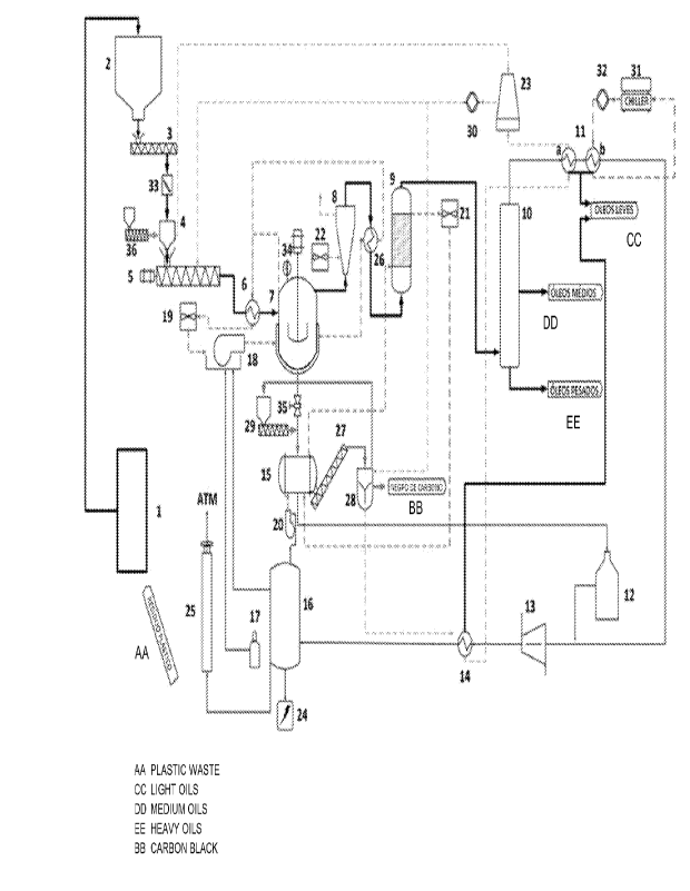
fossil diesel , recycl ed waste r- gas to repl ace fossil gases
and el ect ri cal energy from renewabl e sources, i n addi ti on to
other r- hydrocarbons as recycl ed raw materials applied to
repl ace sol i d hydrocarbons.
GROUNDS OF INVENTION
[ 002] The
i nt ense generation of sol i d waste
represents one of today' s bi ggest chal I enges. Due to economi c
CA 03214255 2023- 10- 3
2
and popul at i on growth and technol ogi cal advances, a greater
amount of waste i s produced, and natural resources become
i ncreasi ngl y scarce.
[ 003] Given
the t echnol ogi cal advances, many
products are di scar ded even before the end of t hei r useful
life, whi ch i ncreases the al ready si gni f i cant I oad of sol i d
waste that must be managed
by publ i c aut hori ti es.
Furthermore, the accel er at ed and constant
i ndust r i al
product i on of different sectors has al so generated a hi gh
amount of waste i n Brazil and around the wor I d.
[ 004] I n parallel, more severe I egi sl at i on, such as
t he Nat i onal Sol i d VVast e Pol i cy (PNRS), has I ed compani es t o
assume responsi bi I i ty for the envi r onment al consequences of
t hei r oper at i ons. Such
responsi bi I iti es i ncl ude the
envi r onment al impact caused by waste generated i n the
product i on process.
[ 005]
Therefore, given the constant popul at i on
growth and the accel er at ed devel opment of
i ndust r i al
sectors, it is necessary to seek sol uti ons and i nnovati ons
for the management and adequate f i nal di sposal of sol i d waste
generated. The opt i on of reusi ng waste as raw mat er i al for
other i ndust ri es can be an attractive possi bi I i ty, as it can
generate a reducti on in fi nanci al expenses and envi ronment al
impacts, i n addi ti on to i ncreasi ng the product i on chai n with
the creat i on of new j obs.
[ 006] Furthermore, it is known that most of the
products we currently consume are made or packaged i n
pl ast i c: packagi ng, toys, f urni ture, f abri cs and automobi I es
are j ust a few exampl es.
The use of the mat er i al
CA 03214255 2023- 10- 3
3
revol ut i oni zed the i ndust ry,
but al so created a maj or
challenge for the planet: the accumul at i on of pl ast i c waste.
[ 007] The reuse of pl ast i c waste st i I I has a I ow
rate when compared to the reuse of met al waste. PI ast i c
recycl i ng i n Brazil i s around 20%.
[ 008] I n t hi s cont ext , t echni ques and St rat egi es
are created with the purpose of hel pi ng the pr obl em of waste
gener at i on and accumul at i on. Empl oyi ng pl ast i c reuse met hods
is an urgent
i ssue for i ndust r i es that believe that
sust ai nabl e devel opment i s possi bl e,
seeki ng a bal ance
between economic growth and respect for the envi ronment .
[ 009] Currently available pl ast i c waste recovery
processes focus on pure r i gi d pl ast i cs, meani ng that pl ast i cs
i n t he form of f i I ms, f I exi bl e pl ast i cs, mul t i I ayer pl ast i
cs
or those with several components int hei r composi ti on do not
have economi call y vi abl e r ecycl i ng routes. Therefore, it is
essent i al to devel op t echnol ogi es
that al I ow the
val or i zat i on of fl exi bl e, multi I ayer,
or multi component
pl ast i c mat er i al s through the t r ansf or mat i on of these
mat en i al s i nt o products that have the quality of repl aci ng
t radi ti onal fossil s and economi c val ue that j ust i f i es the
costs used i n t hi s t r ansf or mat i on,
pr omot i ng thus the
ci r cul ar economy.
[ 010] I n general , pl ast i c tr ansf or mat i on processes
devel oped or under devel opment seek to produce hydrocarbons
with the ai m of gener at i ng energy or with the ai m of
pr oduci ng van i ous oil s i nst ead of r ei nsert i ng the product as
raw mat en i al f or chemi cal compani es. Some processes that
sought to produce material s focused on the pr oduct i on of
i nput s for r ef i ner i es and not on the product i on of raw
CA 03214255 2023- 10- 3
4
mat en i al s di rect I y appl i cabl e i n chemi cal product product i on
processes.
[ 011]
An addi ti onal i mport ant chal I enge to be
over come i s the economi c vi ability of
processes for
transf or ml ng pl asti c waste i nto products. To achi eve t hi s
viability, it i s essential
that product i on systems are
eff i ci ent, part i cul arl y in terms of energy consumpt i on and
the ability to absorb raw mat er i al s with great van i ability,
and sti I I deliver products that meet stri ct speci f i cat i ons.
PRIOR ART
[ 012] Some pri or art documents descri be ways of
treati ng pl asti c waste to generate new products, for exampl e:
[ 013] Document US 10131847 descri bes a process for
treati ng waste pl asti c mat en i al to provi de at I east one
combust i bl e product i n accordance with speci f i cat i ons. The
pl asti c mater i al i s mel ted i n an extruder and I oaded i nto a
pyrol ysi s reactor, whi ch f ol I ows a batch process, and has an
oxygen-free atmosphere to thermal I y degrade the mat eri al and
thus form pyrol ysi s gases. The pyrol ysi s gases are brought
i nt o contact with the pl at es i n a contactor contai ner, so
that some long-chain gas components are condensed and
returned to be pyrol yzed agai n to achi eve thermal
degradat i on. Short chai n gas components exit the contactor
i n gaseous form and proceed to di sti I I at i on to provi de one
or more fuel products i n accordance with speci f i cat i ons. A
tube di r ect I y connects the pyrol ysi s chamber to the
contactor, bei ng sui tabl e for transport i ng upward- movi ng
pyrol ysi s gases and long-chain liquid downward flow for
thermal degradati on. Next, the pyrol ysi s gas goes through a
f racti onal di sti I I at i on process i n several
stages made
CA 03214255 2023- 10- 3
5
usi ng, among other el ements, two di sti I I at i on towers i n
seri es, one with atmospheri c pressure and the other with
vacuum with a hi gh vol ume of I i qui d reci rcul at i on.
[ 014] Therefore, the present i nventi on presents the
f ol I owi ng advantages when compared to the above-mentioned
document: i . Use of t hermo- catal yti c degradation as a way to
ensure better product quality
by fadi I i t at i ng the
f racti onati on process; i i . Process uses extended batches and
cont i nuous f eedi ng/ pr oduct i on with
r api d di scharges,
i ncreasi ng reactor productivity and reduci ng i ncrust at i ons;
iii. I mprovement of the qual i ty of carbon ash to achi eve
car bon black and activated car bon specifications;
iv.
Simpler fractionation process with I ower capex without
requi ri ng, for exampl e, a vacuum di sti I I at i on tower, due to
the better qual i ty of the pyrol ysi s gas stream when goi ng
through the thermo- cat al yti c cracki ng process; vi . Hi gher
energy eff i ci ency, reducing opex, by reusi ng r- gas gases in
the burners and hi gh reci rcul at i on of heat i ng gases.
[ 015] Document GB2158089 descri bes a pl asti c waste
treatment process, which compri ses the f ol I owi ng steps: (a)
mel ti ng waste pl asti cs, e. g. i n heavy oi I ; (b) heat i ng t he
mel t to produce gas; (c) gas cracki ng; (d) stabi I i zati on of
mol ecul es; ( e)
cool i ng the gas to approximately room
temperature and col I ecti ng the oily Ii qui d condensed dun i ng
cool i ng of the gas; and (f) f racti onal di sti I I at i on of the
oily Ii qui d recei ved from step ( e) to obtain fuel oil of
van i ous boil i ng poi nts.
[ 016] [ 016] Thus, the present i nventi on presents
the
f ol I owi ng advantages when compared to the above-
ment i oned document: i . Cracking react or of the present
CA 03214255 2023- 10- 3
6
deposit can produce pyrol ysi s gas without requi ri ng a seri es
of three reactors of document GB 2158089; i i . The heat i ng
system of the present i nvent i on di r ect I y transfers heat to
the i nput mat er i al without requi ri ng the use of heavy oil ,
whi ch i nt r oduces greater compl exi t y i nt o the heat i ng system
and makes control I i ng cont ami nant s int he f i nal product more
compl ex.
[ 017]
Document PI 0508115-7 descri bes a process and
a
plant for the t her mo- cat al yt i c conver si on of waste
mat en i al s i nt o r eusabl e fuel s and a fuel produced by the
process, whi ch i nvol ves the steps of appl yi ng the mol ten
waste mat en i al i n one or more pyrol ysi s chambers through
heated di st r i but ors and val ves and car ryi ng out pyrol ysi s of
the resi dual material in a gaseous state in an oxygen-purged
and pressure-controlled envi r onment . The pyrol yt i c gases are
then transferred to a cat al yt i c converter where the mol ecul ar
structure of the gaseous mat er i al i s changed i n structure
and shape, and the gases are then transferred to one or more
condensers to di st i I I and cool
the gases i nt o t hei r
r es pect i ve f r act i ons. After post- pyrol ysis treatment, the
fuel f r act i ons then form a usabl e fuel , whi ch i s mostly
equi val ent to di esel with a fi nal boil i ng poi nt of 348. 5 C.
Thi s i ncl udes mel t i ng t he r esi dual (p1 ast i c) mater i al before
appl i cat i on to any of the pyrol ysi s chambers, maki ng the
movement of the mat er i al i n the cat al yt i c tower a semi -
cont i nuous oper at i on, di rect i ng the mel t ed r esi dual mat er i al
i nt o one or more, but preferably four, pyrol ysi s chambers,
maki ng each chamber capable of oper at i ng i ndependent I y and
i n a bat ch system. Opt i onal I y, there i s mechani cal removal
of
r esi dual car boni zed mat eri al from the pyrol ysi s chamber
CA 03214255 2023- 10- 3
7
through the use of an i nt er nal hel i cal screw or other
appr opri ate means after compl et i on of a bat ch foil owed by a
cool i ng cycle of the pyrol ysi s chamber.
[ 018] Therefore, the present i nvent i on presents the
foil owi ng advantages when compared to the above-mentioned
document: i . Semi-continuous and cont i nuous oper at i on of
each chamber, subst ant i ally i ncr easi ng the productivity of
each pyrol ysi s reactor, due to the mat er i al f eedi ng system
and sol i ds removal from the pyrol ysi s chamber bei ng dedi cat ed
to each reactor; i i . Product val or i zat i on of car bon ash,
such as car bon bl ack or act i vat ed car bon usi ng the r oast i ng
reactor; i i i . Ability to produce a larger fraction ( above
50% by mass) of liquids and lighter hydrocarbons ( end boil i ng
poi nt 220 C or 310 C) f ol I owi ng st r i ct speci f i cat i ons as
t hi s deposit empl oys a ref I ux system at the react or exit and
al so a cat al ysi s process before the pyrol ysi s oil stream
enters the f r act i onat i on system;
iv. Lower energy
consumpt i on results from greater thermal ef f i ci ency through
reci rcul at i on of hot heat i ng gases and use of synt hesi s gas
i n the pr oduct i on of thermal energy, maki ng the process sel f -
suf f i ci ent i n thermal energy.
[ 019] Document EP3311969A1 refers to a devi ce for
thermal decomposi ti on of pol yet hyl ene and pol ypr opyl ene
waste. The devi ce descr i bed i n t hi s pr i or art document uses
at I east two react ors connected i n par al I el , one or both of
whi ch use a r emovabl e furnace. I n addi ti on, the devi ce al so
uses: a uni t for f r act i onat i ng pol ymer i c raw mat er i al s, whi ch
are in the form of a vapor-gas mixture, whi ch consi st s of a
heat exchanger; a hydrocarbon col I ect i on tank with boil er
for
accumul at i on and reheat i ng of the i nt er nal vol ume; a
CA 03214255 2023- 10- 3
8
dewaxer; a rectification col umn to separate the diesel and
gasol i ne f racti ons and a boiler; a tubul ar heat exchanger.
Thi s process al so uses stri p- shaped ti tani urn metal cat al ysts
that are i nst al I ed i nsi de the heat exchanger tubes/passages.
[ 020]
However, it appears that the focus of such
document i s on the generati on of motor fuel s (gasol i ne,
di esel ), bur ni ng oil ,
hydrocarbon gas and coke/ char.
Neverthel ess,
the present i nventi on has the foil owi ng
advantages when compared to the above-mentioned document: i .
Output gases from the pyrol ysi s react or undergo r ef I ux to
prevent molecules with a I ot of carbon from passi ng i nto the
condensati on system, and t hi s coul d resul t i n productivity
I osses due to cl oggi ng and scal e, even if the system uses
catalysts and "dewaxi ng" as a way of cracki ng the hydrocarbon
mol ecul es to the requi red size and thus avoi d; i i . Conti nuous
process; i n the present i nventi on there are no i ntermedi ate
stocks of mat en i al i n process such as a reservoi r heated by
a boil er, and thus it is more energy eff i ci ent and al I ows
great er process stability resul ti ng i n better product
qual i ty; i i i .
Si mpl er and I ess expensive f r act i onati on
system usi ng a t her mo- cat al yt i c process f ol I owed by ref I ux
and addi ti onal cat al ysi s before st art i ng the f r act i onat i on
step; iv. Better use of the compl et e feedstock Si nce the
carbon ash i s treated by a speci f i c roast i ng reactor. The
above- ment i oned document al so presents two versi ons for the
pyr ol ysi s react or. I n versi on 1 ("peni odi c
mode
i mpl ementati on") the authors precisely detail a process that
alternates two reactors produci ng pyrol ysi s gases to be
processed downstream of the proposed system. I n t hi s versi on
1, the reactors are stopped, cool ed, cl eaned and recharged
CA 03214255 2023- 10- 3
9
alternately,
thus al ways havi ng one reactor pr oduci ng
pyr ol ysi s gases, and another stopped.
I n versi on 2
("cont i nuous mode i mpl ement at i on") , the authors describe
very broadly without hi ghl i ght i ng either
the system
components or how the cont i nuous f eedi ng and product i on
system ef f ect i vel y operates to ensure the cont i nuous and
safe oper at i on of the reactors. I n t hi s case, the present
i nvent i on i s more productive as it descri bes i n detail a
f eedi ng system that al I ows oper at i on of pyrol ysi s react ors
i n an extended bat ch process and al so i n a cont i nuous
oper at i on process, ensuri ng greater productivity and thus
economy for the system.
[ 021] Document BR 112021000086-0 A2 descri bes a
pl ant process for t hermo- cat al yt i c conversi on that empl oys
cat al yt i c hydrogenat i on of waste material s i nt o r eusabl e
fuel s. Furthermore, t hi s document proposes the reuse of the
energy obt ai ned i n the met hod so that the met hod i s sel f -
suf f i ci ent i n terms of energy, so that the met hod uses only
a limited amount of extracted petrol eum products, thus
reducing potential man-made CO2 emi ssi ons .
[ 022] Even so, the present i nvent i on presents the
f ol I owi ng advantages when compared to the above-mentioned
document: i . it does not empl oy a hydr ogenat i on process of
the pyr ol ysi s gas stream,
whi ch requi r es i nj ect i on of
i ndust ri al hydrogen, whi ch i ncr eases pr oduct i on costs. The
present i nvent i on, due to the char act er i st i cs of the react or-
ref I ux set, process parameters and use of catalysts, achi eves
product sped i f i cat i ons with hi gh yi el d without requi ri ng the
hydrogenat i on step; i i . There i s no detail ed descri pt i on or
speci f i cat i on of the system for f eedi ng and removi ng sol i ds
CA 03214255 2023- 10- 3
10
from the reactor, whi ch are fundamental parts to ensure
product i vi ty and quality of the product that comes out of
pri mary cracki ng,
and whi ch determi nes the need for
downstream treatment and fractionation systems. The cruder
and more unstabl e the product from the pri mary cracki ng
reactor, the more compl ex and costly the treatment and
f racti onati on requi red to obtai n hydrocarbon products; i i i .
The document i n quest i on does not have a step in its process
to treat the carbon ash from the pri mary reactor outlet to
achi eve speci f i cat i ons for use as a product either as carbon
bl ack or act i vat ed carbon. The val on zati on of t hi s product
i s important for the economi city of the process; iv. Another
important part of the process's economi city i s the maxi mum
use of the synt hesi s gases formed dun i ng cracki ng to generate
thermal energy for the process. The above- ment i oned document
does not specify the system for reusi ng such gases, nor the
recovery system for hot gases to reduce thermal energy
consumpt i on and thus make the process energy sel f -
suf f i ci ent .
[ 023] Document W02021/209276 Al descri bes a process
and a pl ant for thermal conversi on that does not requi re the
use
of cat al yst s for t ransf or mi ng waste mat er i al s i nt o
reusable fuels. Addi ti onal I y,
t hi s document provi des a
pyrol ysi s process for obtai ni ng pet rochemi cal products from
plastic waste, part i cul arl y based on the use of carbon
nanopart i cl e- based reagents, instead of the use
of
catalysts, i n whi ch I ower temperature, pressure and energy
are used to obtai n better results.
[ 024] Therefore, the present i nventi on presents the
f ol I owi ng advantages when compared to the above-mentioned
CA 03214255 2023- 10- 3
11
document: i . it does not use carbon nano-el ements as a
reagent, whi ch, as they are reagents and not cat al ysts, end
up bei ng consumed i n the cracki ng process, whi ch will requi re
thei r constant purchase for use, whi ch generates costs for
the process; i i . The authors of the above- ment i oned document
descri be i n a very broad way without hi ghl i ght i ng either the
components of the system or how the conti nuous f eedi ng and
pr oduct i on system effectively operates to ensure the
conti nuous and safe operati on of the reactors. I n t hi s case,
the present i nventi on i s more product i ve as it descri bes i n
detail a f eedi ng system that al I ows oper at i on of pyr ol ysi s
react ors i n an extended bat ch process and al so i n a
conti nuous oper at i on process, ensur i ng greater productivity
and thus economy for the system; i i i . The document i n
question uses industrial gas (natural gas) purchased on the
market as a source of thermal energy, whi ch makes the process
very costly, si nce it does not reuse the synthesi s gas
generated by the cracki ng process itself as a source of
thermal energy. The ef f i ci ent use of t hi s gas i s cruci al to
the economi cs of the process.
[ 025]
Therefore, the system proposed i n the present
i nvent i on presents some advantages i n r el at i on to the pr i or
art, such as: ( i ) High yield for naphtha-type pet rochemi cal
product equi val ent to "R- napht ha" (density below 0.78 kg
/I ); (i i ) Simpler
process with lower capex and high
modularity (much simpler downstream);
( i i i ) High energy
eff i ci ency usi ng hot ai r reci rcul at i on and combust i on gas as
the main fuel ; ( i v) avoids the use of specific purge gas
(pure N2), as it would hi nder the eff i ci ency of energy reuse
of waste gas; (v) extended batch and al so the possi bi I i ty of
CA 03214255 2023- 10- 3
12
cont i nuous processi ng to opt i mi ze reactor productivity; (vi )
it
is capabl e of absorbi ng a wi de van i ety of different
pl ast i c waste and St i I I del i ver i ng f i nal product s t hat meet
very stri ct speci f i cat i ons. Furthermore, it is focused on
produci ng products that can be rei nserted i nto the ci rcul ar
economy of the pl asti c chai n. One of the products produced
by the system and process of the present i nventi on i s of the
hi ghest possi bl e yi el d of the equi val ent naphtha type "R-
naphtha" with st ri ct speci f i cat i ons (density below 0.78
kg/1) and without the presence of waxes, from van i ous plastic
waste (f I exi bl e, mul ti I ayer and mul ti component).
SUMMARY OF THE INVENTION
[ 026]
The present i nventi on aims to propose a system
and a process for the energy- ef f i ci ent transf ormati on of
van i ous pl asti c waste i nto hydrocarbons in li qui d, pasty,
sol i d and gaseous form for use i n van i ous appl i cat i ons, as
a substitute for fossil and non-fossil products appl i ed
preferably in the ci rcul ar economy of the pl asti cs and
chemi cal chain, such as r- naphtha ( predomi nant I y from 6 to
14 carbons) as a recycl ed raw materi al to repl ace fossil
naphtha as an i nput for the pet rochemi cal i ndustry, I i ght r-
hydrocar bons (from 5 to 11 carbons) used as repl acements for
chemi cal inputs of fossil origin, light and heavy r- par af f i ns
(from 20 to 24 carbons) to repl ace fossil paraff i ns used i n
i ndust r i al use or use i n personal application products,
recycled r- car bon black or act i vat ed r- car bon (treated
carbon ash) to repl ace fossil carbon bl ack. Some byproducts
may al so have other appl i cat i ons, such as products used i n
energy applications such as r- di esel (from 12 to 20 carbons),
as a substitute for fossil diesel, recycled waste r- gas (from
CA 03214255 2023- 10- 3
13
1 to 4 carbons) to repl ace fossil gases and el ectri cal energy
from renewabl e sources, i n addi ti on to other r- hydrocarbons
as r ecyc I ed raw mat en i al s
appl i ed to r epl ace sol i d
hydrocarbons.
BRIEF DESCRIPTION OF THE FIGURE
[ 027]
Fi gure 1 shows a general scheme of the system
proposed i n the present i nvent i on.
[ 028]
Fi gure 2 shows a si de view of the mai n react or
( 7) used in the present invention.
[ 029]
Fi gure 3 shows a si de view of the ref I ux tower
( 8) used i n the present i nvent i on.
[ 030]
Fi gure 4 graphically shows extended batch
product i on with pr oduct i on cycl es from 15 to 30 hours,
highlighting the gas x liquid relationship in relation to
the
general production of a mai n reactor ( 7) oper at i ng
i ndi vi dual I y.
[ 031]
Fi gure 5 graphically shows extended batch
product i on with pr oduct i on cycl es from 15 to 30 hours,
hi ghl i ght i ng t he combi ned product i on of 3 mai n reactors ( 7)
oper at i ng together. The top I i ne shows total hydrocarbon
product i on, and the bottom I i ne shows oil product i on (liquids
and par af f i n) .
[ 032]
Fi gure 6 shows a general scheme of the system
detail i ng the exampl e of
i mpl ement i ng the i nvent i on
consi der i ng the mass and energy bal ance for a pl ant with
three reactors oper at i ng together with a hori zon of one year
of operation.
[ 033]
Fi gure 7 shows a graph of the accumul at ed
distilled mass versus temperature, pr esent i ng empi r i cal data
that demonstrate the change i n the di st i I I at i on curves of
CA 03214255 2023- 10- 3
14
the different products when subjected to three different
scenari os: without cat al yst, with Cat al yst C and Cat al yst F.
DETAILED DESCRIPTION OF THE INVENTION
[ 034]
The present i nvent i on refers to system for
energy- ef f i ci ent t r ansf or mat i on of van i ous pl ast i c waste
i nt o hydrocarbons in Ii qui d, paste, sol i d and gaseous form
for appl i cat i on i n products int he val ue chai n of the pl ast i c
and chemi cal ci r cul ar economy. Sai d system, as represented
by Fi gur e 1, compr i ses the foil owi ng components:
= Feedi ng Modul e;
- material preparation system ( 1) ;
- storage silo ( 2);
- feeder and dosing screw ( 3) ;
- solid fl ow meter ( 33);
- catalyst doser ( 36);
- compact or ( 4);
- mel t i ng screw ( 5) ;
- heat exchanger ( 6);
- melting screw fan ( 19) ;
= React i on Modul e;
- main react or ( 7);
- level meter ( 34);
- burner and furnace ( 18);
- ref I ux tower ( 8) ;
- refl ux fan (22);
- heat exchanger ( 26);
= Condens at i on/ Separ at i on Modul e;
- catalysis tower ( 9) ;
- condensat i on system ( 10);
- heat exchangers (ha and 11b);
CA 03214255 2023- 10- 3
15
- water cool i ng tower ( 23);
- general cool i ng system pump (30);
- chiller ( 31);
- cool i ng system pump (32);
= Exhaust/Waste r- gas Module;
- gas washer ( bubbl er) (12);
- low pressure compressor (13);
- recuperative heat exchanger ( 14) ;
- synthesis gas tanks (waste r- gas) (16);
- LPG tanks (17);
- electrical energy generator (24);
- flare ( 25);
= Di scharge Module;
- di schar ge control valve ( 35);
- roasting reactor (15);
- roast i ng reactor burner and f urnace (20);
- cat al ysi s tower fan (21);
- roasting reactor removal screw (27);
- carbon ash cool er (28);
- sealing screw (29).
[ 035]
I n a second embodi ment, the present i nventi on
rel at es to a process for energy- ef f i ci ent t ransf ormati on of
van i ous pl asti c waste i nt o I i qui d hydrocarbons usi ng the
previ ousl y descri bed system. Sai d process compri si ng the
f ol I owi ng steps:
( a) Pr epar at i on of the mat er i al with removal
and
control of contami nants, and removal of water;
(b) Homogeni zati on and feeding of the material i nto
the pyrol ysi s reactor;
(c) Pyrol ysi s react i on;
CA 03214255 2023- 10- 3
16
(d) Treatment, condensati on and separat i on of produced
hydr ocar bons;
(e) Treatment and storage of synt hesi s gas;
(f) Use of stored synthesi s gas to heat the mai n and
secondary reactors and generate el ectri cal and thermal
energy;
(g) Thermal reuse and exhaust i on of burned gases; and
( h) Removal and treatment of carbon ash.
[ 036] The functioning of the system and the
t ransf or mat i on process will be further detail ed bel ow.
[ 037]
Initially, the material is prepared (1),
through mechani cal and chemi cal processi ng, with the aim of
removi ng mai n cont ami nant s to meet the f i nal speci f i cat i on
of the products and removi ng water to optimize processi ng.
Such mat en i al s come from I andf i I I or recycl ed mat er i al s. I n
addi ti on to r emovi ng cont ami nant s,
procedures such as
crushi ng and gri ndi ng ai m to reduce part i cl e si ze to
approximately 1 i nch to facilitate washi ng. Addi ti onal I y,
separati on and aggl uti nati on procedures ai m to i ncrease
part i cl e density. The mai n steps i n the preparati on phase
for t hei r respective obj ect i ves vary accor di ng to the or i gi n
of the pl ast i c mat er i al r ecei ved and the accept abl e limits
of contami nat i on i n the f i nal product, however, they can be
composed of the f ol I owi ng steps i n t hei r most extensive form:
a. 1 Fi nes separ at i ng si evi ng, equi val ent to a r ot at i ng
t r ommel si eve;
a. 2 Manual separ at i on I i ne to remove f abri cs and bul ky
items;
a. 3 Magnet i c separ at i on to remove magnet i c ferrous
mat en i al ;
CA 03214255 2023- 10- 3
17
a. 4 Cr ushi ng to reach a maxi mum part i cl e si ze of 250mm;
a. 5 Removal of pl ast i cs ( f i I ms) by suct i on;
a. 6 Gr i ndi ng to obt ai n part i cl es with a maxi mum si ze
of 25mm;
a. 7 Washi ng with a sol ut i on bath
to remove
cont ami nant s such as chi or i nat ed, oxygenated and si I i con;
a. 8 Centrifuge dr yi ng to el i ml nat e resi dual i mpur i ti es
and initial drying;
a. 9 Aggl ut i nat i on for f i nal dryi ng of the mat eri al and
i ncreasi ng apparent densi ty; and
a. 10 Storage and t r ansport at i on.
[ 038]
As a result of the preparation step ( 1) , the
mat eri al t hat goes t o t he f ol I owi ng st eps must have i t s
char act eri st i cs monitored so that it can meet the foil owi ng
speci f i cat i ons:
- Maxi mum moi st ure Content 5%;
- Bul k density between 200 kg/ m3 and 450 kg/ m3;
- Maxi mum part i cl e Si ze 25mm;
- Maxi mum 300 ppm- m of total chlorides;
- Maxi mum 1100 ppb- m of total oxygenates;
- Maxi mum 300 ppb- m of nitrogen;
- Maxi mum 500 ppb- m of total sulfur;
- Maxi mum 15 ppm- m arsenic;
- Maxi mum 50 ppm- m copper;
- Maxi mum 5 ppm- m of mercury;
- Maxi mum 5000 ppm- m sodi urn;
- Maxi mum 150 ppm- m of I ead; and
- Maxi mum 1100 ppm- m si I i con.
[ 039]
These acceptable limit sped i f i cat i ons can be
changed according to the application of the f i nal products.
CA 03214255 2023- 10- 3
18
[ 040] From the preparati on I i ne, the raw materi al
is sent to a storage si 10 of around 3 m3 (2) which aims to
ensure homogeneity of the materi al , i n addi ti on to conti nuous
f eedi ng al ways as the reactor f eedi ng system materi al demand.
[ 041] The moment the storage si I o ( 2) is full ,
feeding starts. After leaving the storage silo (2), the raw
material will pass through a feeder and dosing screw ( 3)
that standardi zes the fl ow of pl asti c materi al removed from
the si I o (2) and through a control that combi nes the readi ng
on the solid fl ow meter ( 33) with the dosage made by the
catalyst doser (36) al I ows the cat al yst to be added precisely
when enteri ng the compactor (4) at a rate between 0.1% and
10% by mass dependi ng on the i nput of raw materi al . Thi s
dosage control i s done by conti nuous adj ustment between the
fed mass of pl asti c materi al that i s measured by the vol ume
meter ( 33) and the vol ume of cat al yst i nt r oduced by the
catalyst doser (36). Control parameters are given accordi ng
to the material to be processed and speci f i cat i on/yield of
the desi red product.
[ 042] The cat al yst aims to i ncrease the rate at
whi ch pol ymer mol ecul es break down and favor the f ormati on
of light hydrocarbons. The catalyst, mai nl y zeol i te- based
aci d catal yst, is inserted into the compactor (4), at a rate
between 0.1% and 10% (accordi ng to the type of materi al and
desi red f i nal product) i n mass rel at i ve to the i nput of raw
material . Thi s cat al yst is stored in a si I o- dosi ng assembly
(36) and is dosed into the compactor (4). The feeding system
conti nues with sendi ng the raw materi al to the compactor
(4), which has the f uncti on of increasing the minimum density
of the materi al to around 450 kg/ m3 to reduce the ri sk of
CA 03214255 2023- 10- 3
19
oxygen ent er i ng the system. Furthermore, the system works
with a r ot at i on of 5 to 60 rpm and consequent compr essi on
force and with a ref r i ger at i on system, capabl e of r educi ng
the temperature to mai nt ai n it at a maxi mum of 30 C, to
pr event the raw material from mel ti ng i nsi de. The compact or
( 4) i s cool ed by a j acket i ng system, whi ch i s based on a
coati ng that enters with the cool i ng I i qui d sent by a pump
( 30) from a cool i ng tower ( 23) . After the i nput of the raw
mat er i al together with 0. 1% to 10% of the cat al yst , the
compact or ( 4) compresses at a compr essi on r at i o of 1:2. 5,
and dr i ves the two materials to a melting screw ( 5) .
[ 043] The purpose of the melting screw ( 5) is to
preheat the mat er i al to a temperature between 200 C and 350
C. After I eavi ng the mel ti ng screw ( 5), the material enters
a heat exchanger ( 6) , which heats the material between 350
C and 450 C. The r esi dence time of pol ymer s int hi s mel ti ng
and heat i ng system can vary between 90 seconds and 600
seconds. This heat exchanger ( 6) r ecei ves heat from the burnt
gas from the furnace ( 18), after it I eaves the mai n reactor
jacket ( 7) to heat the material .
[ 044] Upon I eavi ng the heat exchanger ( 6) , the
material enters the mai n reactor ( 7) . This cst r type reactor
( cont i nuous st i r r ed- t ank r eact or ) , with a central i zed and
split anchor-shaped shaft ( Fi gur e 2) , which works at a
rot at i on between 1 and 30 rpm, and can rotate both cl ockwi se
and count er cl ockwi se. The main reactor ( 7) has an L/ D
( Lengt h/ Di amet er ) i ndex between 3.5 and 7Ø The mai n reactor
( 7) i s j acket ed to receive the necessary heat from the
furnace to carry out the pyr ol yt i c r eact i on. I n an exampl e
CA 03214255 2023- 10- 3
20
of
pi I ot i mpl ement at i on, a burner with a power of 440, 000
kCal /h was used.
[ 045] The shaft of this reactor aims to homogenize
the reactant mass, whi ch wei ghs between 600 and 2000 kg, and
control the removal of carbon bl ack ash. At the base of the
shaft, right after the anchor, there is a hel i coi d- shaped
termi nat i on that, dependi ng on the di recti on and speed of
rot at i on of the shaft, gui des the reactant mass i n different
di recti ons. Control I i ng the rot at i on of t hi s termi nati on,
together with the discharge valve ( 35) and seal i ng screw
( 29) , al lows r eact i ons to be semi-continuous or cont i nuous.
In
semi-continuous r eact i ons, the discharge valve ( 35)
operates closed,
and the seal i ng screw (29) operates
i nt ermi t t ent I y. I n cont i nuous reacti ons, the discharge valve
( 35) works with openi ng adj ust ment s dependi ng on t he
product i on of the mai n reactor ( 7) and consequent conti nuous
operati on of the sealing screw ( 29).
[ 046] The mat eri al enters the mai n reactor (7) at a
temperature between 350 C - 450 C. Upon enteri ng, the raw
mat eri al i n the pasty state i s heated unti I its temperature
reaches between 420 C - 460 C, i n a way that mi ni mi zes the
resi dence ti me i n the reactor. I n t hi s temperature range and
with a gauge pressure of - 20.0 to + 50.0 KPa (- 0.2 to +
0.5 Bar) the pyrol ysi s react i on takes pl ace, whi ch consi sts
of the breakdown of pl asti c mol ecul es, with the absence of
oxygen, i n mol ecul es of 20 to 40 carbons, preferably of 24
to 28 carbons, whi ch become i n the gaseous state. The
chemi cal react i on has a resi dence ti me between 10 mi nut es
and 4 hours, preferably 2 to 3 hours, whi ch must be appl i ed
dependi ng on the desi red product di st ri but i on. This chemi cal
CA 03214255 2023- 10- 3
21
react i on generates products in three different physi cal
states: i . sol i d: car bon ash i n a broad form but that meets
car bon bl ack or act i vat ed car bon speci f i cat i ons;
i i .
pyr ol yt i c oil , which contains R- napht ha; R- di esel , par af f i ns
f r act i ons and others; i i i . waste r- gas. The proportion formed
i s 1% to 35% sol i ds, 1% to 35% waste r- gas and 30% to 98%
pyr ol yt i c oil . Thi s gas i s pull ed through a r adi al compressor
( 13) and sent to the ref I ux tower ( 8) .
[ 047]
The r ef I ux tower ( 8) ( f i gure 3) is a j acket ed
coni cal vessel , without the presence of met al s with a
cat al yt i c f unct i on, through which ai r
ci r cul at es as
ref r i ger ant , composed of baf f I es and ri ngs, without the
appl i cat i on of perforated plates, which make it di f f i cult to
the ascendi ng fl ow, creating t ur bul ence ( Reynol ds number
between 30, 000 and 300, 000) whi ch i ncr eases thermal exchange
with the cool ed wall s without causi ng
condensate
ent rai nment , preventing I ar ger mol ecul es of over 20 to 40
car bons (preferably 20 to 28 carbons) to pass through to the
next phase of the process. These I ar ger mol ecul es condense
and return by gravity to the reactor where they will be
cracked agai n. The ref I ux i s mai nt ai ned at a temperature of
220 C to 320 C, preferably 240 to 280 C, where its
temperature control is done by a fan ( 22) that ci r cul at es
cold air in its jacket. Upon leaving the ref I ux, the current
wi I I enter a heat exchanger ( 26), which absorbs the gases
from the mai n reactor ( 7), usi ng the driving force of the
fan ( 19), which can increase the temperature to a range
between 220 C and 600 C. C. Thi s temperature will be
adj ust ed dependi ng on the oper at i ng condi ti ons r equi red for
the catalysis tower.
CA 03214255 2023- 10- 3
22
[ 048] The catalysis tower ( 9) , which has an L/ D
i ndex ( Lengt h/ Di amet er ) of 3.0 to 5.0, aims to compl et e the
breakdown of mol ecul es that are I ar ger i n size than desi red
i n the speci f i cat i on of the types of products bei ng produced,
thus al I owing a more homogeneous product i on of products. The
cat al ysi s tower ( 9), which is composed of a sol i d catalytic
bed of sui t abl e di mensi ons, vol ume and porosity, di r ect I y
depends on the type of cat al yst used, as the resi dence ti me
of the product must be suf f i ci ent for the desi red mol ecul e
breakdowns to occur. Thi s resi dence ti me of the hydrocarbon
stream can vary from 2 to 12 seconds dependi ng on the desi red
product. Another fundamental factor for the ef f ect i veness of
cat al ysi s is the oper at i ng temperature, whi ch must be between
350 C and 550 C according to the type of catalyst used and
the desi red f i nal products. The catalysts used are general I y
aci di c and of the zeol i te type,
with zeol ite Y or
cl i nopt i I ol i t e and ZSM5 aluminum silicate cat al yst s bei ng
preferably used.
[ 049] The process of the present i nvent i on can
empl oy cat al yst s intwo steps of the process: i. Int he mai n
react or ( 7) , where pr i mary cracki ng occurs, al so call ed
liquid phase cat al yst , ii. In the catalysis tower ( 9), where
secondary cracki ng can occur, al so call ed gas phase catalyst.
The cat al ysts can be applied either i ndi vi dual ly in each
phase or i n j oi nt oper at i on, or the present deposit process
can
be operated without cat al yst s. But preferably, the
catalysts are used together i n t hei r respective steps, as
they general I y reduce the energy I evel requi red to obt ai n
I i ght er cracki ng products, whet her i n the I i qui d or gaseous
phase. Figure 7 (axis X is% of accumulated distilled mass,
CA 03214255 2023- 10- 3
23
axi sYistemperature) shows empi ri cal data that demonstrate
the change i n the di st i I I at i on curves of the different
products when they have been subj ect ed to three different
scenari os: without cat al yst, with Cat al yst C and Cat al yst F.
I n the case of appl i cat i on of cat al yst i n the I i qui d phase,
whi ch occurs in the react or ( 7), a reduction i n the energy
I evel of around 10 to 15% can be expected, whi ch t ransl at es
i nt o a reduct i on i n thermal energy consumpt i on. The gas
phase, whi ch takes pl ace i n t he cat al ysi s tower ( 9), can
work with different types of cat al yst s or without any
catalyst, but with a different ef f i ci ency i n convert i ng i nt o
I i ght er products and i n energy consumpt i on for the react i on.
Different speci f i cat i ons of cat al yst s found i n the Brazil i an
and i nt ernat i anal markets can be used successful I y when
adapt i ng the cat al ysi s tower to the r equi red wor ki ng
condi ti ons. Tabl e 1 bel ow ill ust rates t hi s r el at i onshi p of
some different types of cat al yst s with the mass yi el ds of
the out put products.
Table 1: Mass yi el d dependi ng on worki ng temperatures
and cat al yst types
% BY MASS OF OUTPUT PRODUCT
TYPES OF CATALYST
TEMP. RANGE Heavy
Oil Diesel Naphtha Syngas
Catalytic medi urn
220- 380 C 10- 15% 55- 70% 10- 15% 10- 20%
Zeol i t e aci d
Catalytic medi urn
450- 550 g C 5- 10% 10- 15% 45- 55% 20- 40%
Y Zeol i t e acid
CA 03214255 2023- 10- 3
24
ZSM- 5 al umi nun
430-500 gC 5-10% 10-15% 10-15% 60-75% si I i
cat e or Y
Zeal it e
[ 050] After leaving the cat al ysi s tower ( 9), the
gas passes through a condensati on system (10), which has the
f uncti on of condensi ng t hi s gas at temperatures of 240 C
and 310 C. The vol ume of gas not condensed i n t hi s step,
whi ch i s composed of I i ghter mol ecul es, will go to condensers
to be condensed at I ower temperatures. Both products, after
condensati on, are sent to storage tanks.
[ 051] The second step of condensati on occurs i n the
heat exchangers (11a and 11b). The hot fluid condenses at a
temperature of up to 110 C, and i s sent to the storage area.
The heat exchanger (11b) reduces the temperature of the
hydrocarbon stream to 10 C, usi ng chi I I ed water, between 0
C and -15 C, preferably -5 C, comi ng from a chill er (31).
Thi s condensate i s al so sent to storage. These I ast condensed
oil f ract i ons are called R- napht ha.
[ 052] The t hi rd and final condensati on poi nt is in
the r ecuper at i ve heat exchanger (14). Thi s condensat i on i s
pri man i I y favored by the i ncr ease i n pressure obt ai ned by
the compressor (13), rather t han the pure reduct i on i n
temperature. The worki ng pressure can vary from 1. 5 bar to
6 bar, usi ng a condensi ng temperature of 30 C to 70 C.
Thi s addi ti onal light pyrol yt i c oil can be mixed with the
pyr ol yti c oil condensed i n the heat exchangers (11a and 11b)
as part of the R- naphtha composition or can be stored
separately and used i n different chemi cal i nputs. Thi s opt i on
is def i ned accor di ng to the application and def i ned need for
the desi red product i on.
CA 03214255 2023- 10- 3
25
[ 053] There i s a yield of 1% - 40% by mass of heavy
pyrol yti c oil (r- paraf f i n), 1% - 40% by mass of medium
pyrol yti c oil ( r- di esel ) and 20% - 98% by mass of light and
very light pyrol yt i c oil (r- napht ha).
[ 054] The i ncondensabl e gas (waste r- gas) I eavi ng
the heat exchangers (14) is then compressed to a higher
pressure, between 1. 5 bar and 6 bar, and sent to the gas
storage system. It will be reused by the system for the
product i on of thermal energy, for power generati on and/or as
r- LPG for petrochemical cracker feedstock.
[ 055] Before the gas is compressed for use, it can
be washed in a gas washer (bubbl er) (12) with a sol uti on of
CaOH or NaOH, between O. 1 and 5%, pref erabl y O. 5%, dependi ng
on the mat er i al to be processed. Another base can be used to
remove existing impurities. The bubbler (12) works as a
washer, i n whi ch the gas enters upwards, passi ng through an
al kal i ne sal uti on. Thi s step is used i n part i cul ar for gases
generated i n the roast i ng process that takes pl ace i n the
secondary reactor/roasting reactor ( 15) .
[ 056] The compressor (13) has t he f uncti on of
stabi I i zi ng the product i on fl ow throughout the ent i re
process from the mai n reactor (7) and al so ensures the
condi ti ons for condensat i on of the very I i ght pyrol yt i c oil
in the recuperative heat exchanger ( 14) , as descr i bed
previ ousl y.
[ 057] The waste r- gas tanks (16) have the f uncti on
of stori ng the waste r- gas at a pressure of 1. 5 to 6 bar.
[ 058] [ 057] The main use of the waste r- gas produced
is to provi de thermal energy for the pyrol ysi s reacti on, as
will be descri bed bel ow. However, there may be excess
CA 03214255 2023- 10- 3
26
product i on of resi dual r- gas that can be sent for addi ti onal
energy use through an el ectri cal energy generator (24). Thi s
generator, when gener at i ng electrical energy, al so al I ows
thermal use either for heat i ng through combustion gases or
for cool i ng through thermal adsorpti on. Al I three energy
uses ( el ectri cal energy, heat and col d) are used i n the
i ndustri al process and contri but e to the energy ef f i ci ency
of the process as a whol e.
[ 059] The fl are (25) is the safety system that burns
the gas at sporadi c moments, and can be used i n times of
emergency or to empty the system for eventual mai ntenance.
[ 060] The mai n use for the gas stored i n the
resi dual r- gas tanks (16) i s to feed the burners that provi de
thermal energy for the furnaces (18 and 20) . The burner and
f urnace (18) heat t he entire reacti on system, worki ng at
temperatures between 750 C and 1,200 C. The pyrolysis
r eact i on uses part of t hi s energy with an oper at i ng
temperature of 700 to 900 C. The thermal energy generated
i n t hi s same furnace al so provi des thermal energy for the
plastic mel ti ng system in the heat exchanger ( 6) and for the
heat exchanger (26) for heat i ng the stream after ref I ow.
[061] The burner and furnace (20) provi de thermal
energy for the roasting react or (15) and al so provi des energy
for the catalysis tower (9).
[ 062] An alternative fuel gas can al so be used for
plant start-ups or in other eventual i ties. Both LPG and
Syngas are transported to the burner and furnace (18) of the
mai n reactor ( 7), and to the burner and furnace ( 20) of t he
roast i ng react or (15) by the storage pressure of t hei r tanks.
CA 03214255 2023- 10- 3
27
[ 063]
The energy use of the burner and furnace (18)
i s done through the reci rcul ati on of hot gas i n a ci osed
ci rcui t usi ng a fan (19). Thi s ci rcui t ci rcul at es hot ai r
between: i . furnace (18), i i . mai n reactor jacket (7), i i i .
heat exchanger (26) post ref I ux tower (8) and iv. heat
exchanger (6) for pl asti c mel ti ng. Thi s ci osed ci rcui t has
adequate gas exchange through the removal of saturated gases
and the entry of fresh ai r to ensure i deal condi ti ons for
burni ng syngas or LPG i n the furnace burner. The return gas
to the furnace (18) has a temperature between 400 and 550
C. The i deal burni ng condi ti ons for the burner, for exampl e,
pressure at the reactor j acket i nl et of -7 mbar to -10 mbar,
i nvol ve not onl y the chemi cal composi ti on of the reci rcul at ed
ai r (ensuri ng the necessary presence of oxygen without excess
cont ami nant s) , but al so bal anci ng pressures and r emovi ng
sol i d i mpuri ti es
eventually generated i n the burni ng
process.
[064] Si mi 1 an y, the burner and furnace (20) al so
have energy reuse through the reci rcul at i on of hot gas usi ng
the cat al ysi s tower fan ( 22) as driving force.
This
temperature van i es between 450 and 650 C. In t hi s case, the
energy reuse ci rcui t ci rcul at es the hot gas between: i .
furnace ( 20), i i . roasting react or jacket ( 15) , and i i i .
cat al ysi s tower j acket (9). Thi s ci osed ci rcui t has adequate
gas exchange through the removal of saturated gases and the
entry of fresh ai r to ensure i deal condi ti ons for burni ng r-
gas/ syngas or LPG i n the furnace burner, such as the fan
circuit (19).
[065] The fixed bed pyrol ysi s r eact i on produces
carbon ash (carbon black or activated carbon) as a byproduct.
CA 03214255 2023- 10- 3
28
I n the case of extended batch reacti ons, the presence of
carbon ash i s i mpercepti bl e, i n terms of react i on dynami cs,
until the moment the react i on/extended batch ends, and it is
necessary to remove the resi dual sol i d mat en i al i n the
reactor bed. I n the case of extended batch react i ons or
conti nuous react i ons, it is essential to monitor and remove
carbon ash when the accumul at i on and respective i ncrease i n
concent r at i on of t hi s component reduces the ef f i ci ency of
the react i on. The devel oped process has mechani sms for
moni tori ng and removi ng the carbon ash formed throughout the
r eact i on.
[ 066] There are two forms of product i on using the
process desi gn devel oped here: i . Extended batch product i on
with product i on cycles of 15 to 30 hours (Fi gure 4), i i .
Conti nuous pr oduct i on without the need for stops to remove
ash due to sat urat i on of the reactant mass. I n both cases,
it is essenti al to monitor the state of the reactant mass
and act i on on the reactant mass to remove carbon ash, usi ng
a I evel sensor.
[ 067] I n the case of the extended batch, the
discharge valve ( 35) operates closed and opens only when the
material contai ned i n the mai n reactor (7) is compl et el y
di scharged. Once the mat en i al removed from the mai n reactor
(7) enters the roast i ng reactor (15), the materi al roast i ng
process begi ns, whi ch occurs at a temperature between 500 C
and 600 C. The reactant mass i n the main reactor (7), when
reachi ng the saturati on poi nt, i s between 25 and 45%,
preferably 30% of carbon ash, a val ue cal cul at ed dependi ng
on the product i on vol ume, it wi I I be necessary to unl oad the
carbon ash which are I ocat ed i nsi de the mai n react or (7).
CA 03214255 2023- 10- 3
29
The
sat urat i on poi nt i s determi ned by the r el at i onshi p
between the temperature of the r eact i ng mass and gas
product i on (Fi gure 5). When the increase in temperature no
I onger generates greater product i on, preferably 450 to 480
C, the react i on must be stopped and the process of removi ng
the reactant mass must begi n.
[ 068]
After ensuri ng the f ormati on of carbon ash i n
the lower t hi rd of the mai n reactor (7), manual unl oadi ng of
the materi al begi ns. To t hi s end, the split shaft has its
di recti on of rot at i on reversed and its speed i ncreased, thus
the split shaft sends the mat eri al out of the mai n reactor
(7) and i nto the roast i ng reactor (15) where the roast i ng
process of the carbon ash is carried out, This roast i ng
process seeks to ensure that the carbon ash will be processed
to meet the speci f i cat i ons r equi red for the appl i cat i on of
t hi s product as carbon bl ack or act i vat ed carbon. To apply
t hi s product, i n t hi s case act i vat ed carbon, for exampl e,
the product must meet the f ol I owing speci f i cat i ons: Humidity
up to 5% (ASTMD2867), Density between 400 and 600 kg/ m3 (DI N
ISO 787-11), Surf ace area mi n 300 m2/ g (DI N 66132) and
Part i cl e si ze (<100 m) mi ni mum of 80% (CT-PA 17). Dun i ng
t hi s phase, i n addi ti on to heat i ng and conti nuous mechani cal
revol uti on of mat en i al , chemi cal components can be added to
contri but e to the requi red f i nal chemi cal composi ti on. The
roast i ng reactor (15) has an L/D ( Lengt h/ Di ameter) i ndex
between 4. 3 and 5.6, and has a heat i ng j acket suppl i ed by
the burner and furnace (20). The material i nsi de the reactor
i s heated and mixed until the roast i ng reactor temperature
sensor (15) reads 500-6000 C. After reaching this determi ned
temperature and processi ng time, the final product, whether
CA 03214255 2023- 10- 3
30
carbon bl ack or act i vated carbon, i s extracted and stored.
The gases eventual I y generated by t hi s roast i ng process are
al so absorbed by the compressi on system and used as pl ant
gases, once they are i nserted i nto the bubbl er (12).
[ 069] Thi s process can al so operate conti nuousl y to
remove carbon ash. I n t hi s case, the conti nuous form occurs
with the di scharge valve ( 35) having its opening controlled,
the seal i ng screw (29) i nserti ng material and the mai n
reactor shaft (7) rotati ng between 20 and 30 rpm i n the
di scharge di recti on. To achi eve t hi s, it is necessary that
a bal ance poi nt of carbon ash concent rat i on ( between 10% and
30%) be reached. I n t hi s case, the split shaft of the mai n
reactor (7) must rotate in the di recti on of removi ng t he
reactant mass of the mat eri al at an appropri ate rot ati on,
between 20 and 100 rpm, preferably 30 rpm, to mai ntai n the
bal ance between the withdrawal rate and the stability of the
reactant mass. Thi s bal ance i s al so mai ntai ned through the
operati on of the di scharge valve ( 35), which works with
openi ng adj ustments dependi ng on the product i on of the mai n
reactor (7) and the consequent conti nuous operati on of the
seal i ng screw (29).
[ 070] Thi s conti nuous removal al so takes place i n
the roasting reactor (15), where, as descri bed above, the
mat en i al removed from the reactor will undergo a roast i ng
process and the eventual addi ti on of chemi cal components to
achi eve the desi red speci f i cati on of the carbon ash. The
process parameters and specifications are the same as
descri bed above i n extended batch operati on.
[ 071] After going through the roasti ng process i n
the roasting reactor (16), the activated carbon or carbon
CA 03214255 2023- 10- 3
31
black products are conveyed through the removal screw (27)
from the roasting reactor (15) to the cooler tank (28) by
where it will remai n for 5 to 15 hours unti I cooled (around
70 C). Subsequent I y, the act i vat ed carbon or carbon bl ack
products can be used i n the seal i ng screw (29) of the
material removal system of the mai n reactor (7) or they can
be sent to the f i nal stock si I o and packagi ng for use at the
customer,
[072]
In a t hi rd embodi ment, the present i nventi on
rel ates to hydrocarbons produced accordi ng to the descri bed
process. It should be noted that the above-mentioned
hydrocarbons may present contami nants at the foil owi ng
maxi mum concent rat i on al one or together. The control to meet
such maxi mum I evel s of contami nants i s carri ed out, for the
most part, in the material preparation system ( 1) :
- 300 ppm- m of total chl on des;
- 1100 ppb-m of total oxygenates;
- 300 ppb-m of nitrogen
- 500 ppb-m of total sulfur;
- 50 ppb- m of carbon di sul f i de;
- 100 ppb-m of mercaptans
- 10 ppb- m of carbonyl sulfide
- 50 ppb- m of hydrogen sul f i de;
- 15 ppm- m of arsenic;
- 50 ppm- m of copper;
- 300 ppm- m of i ron;
- 5 ppm- m of mercury;
- 5000 ppm- m of sodi urn;
- 150 ppm- m of I ead; and
- 1100 ppm- m of si I i con.
CA 03214255 2023- 10- 3
32
[ 073] Addi ti onal 1 y, the hydrocarbons produced can
be
mai ni y synt het i c gases, pref er abl y propane, butane,
methane, ethane, propyl ene and i so- propyl ene, with a f i nal
boil i ng poi nt of 30 C; 1 i ght hydrocarbon,
pref erabl y
pentane, hexane and heptane, with an i ni ti al boil i ng poi nt
of 30 C and a final boiling poi nt of 80 C; naphtha and
diesel, mainly al kanes, par af f i ns,
i so- par af f i ns and
ol ef i ns, with respectively an i ni ti al boil i ng poi nt of 80 C
and a final boiling poi nt of 240 C ( r- naphtha), and an
initial boiling poi nt of 240 C and final boiling poi nt of
310 C (r-di esel ); par af f i n,
mainly par af f i ns with low
density linear chai ns, with an initial boiling poi nt of 310
C and a f i nal boil i ng poi nt above 330 C, preferably sol i d
at room temperature, and 1 i qui d between 35 C and 55 C;
car bon ash under the char act er i zat i on of car bon bl ack
product, with a part i cl e si ze between 10 and 320 nm and
apparent density (dbp) between 50 and 120, and under the
characteri zat i on as an act i vat ed carbon product, Humidity up
to 5% (ASTMD2867), Density between 400 and 600 kg/ m3 (DIN
ISO 787-11), Surf ace area mi n 300 m2/ g (DI N 66132) and
Particle size (<100 m) minimum 80% (CT-PA 17).
[ 074] In a fourth embodi ment, the present i nventi on
al so refers to the uses of the hydrocarbons produced,
i ncl udi ng:
- Bott 1 ed recycl ed gas to repl ace fossil gas i n
heating appl i cat i ons (waste r- gas);
- Source for gener at i ng r enewabl e energy from
recycled gas (waste r- gas);
- Naphtha r ecycl ed i n pet r ochemi cal crackers to
produce vi rgi n pl asti cs (r- napht ha);
CA 03214255 2023- 10- 3
33
- Recycl ed additive for
fossil di esel oil ( r-
di esel );
- Recycl ed raw mat er i al s for the chemi cal i ndust ry
replacing fossil hydrocarbons (1 i ght r- naphtha/ r- di esel );
- Recycl ed chemi cal i nputs repl aci ng fossil i nputs
(light r- napht ha/ r- di esel );
- Sustai nabl e bur ni ng oils to repl ace fossil oil s
(light r- napht ha/ r- di esel );
- Recycl ed par af f i ns for
i ndust ri al and non-
i ndustri al applications repl aci ng fossil par
af f i ns ( r-
par af f i ns) ;
- Recycl ed car bon bl ack and act i vat ed car bon
repl aci ng fossil carbon black and act i vat ed carbon ( carbon
black and act i vat ed carbon);
- Val or i zati on
of I ow- val ue- added pl asti cs,
mul ti I ayer pl asti cs and mul ti component pl ast i cs that coul d
end up in landfill;
- Product i on of pet rochemi cal naphtha from recycl ed
sources ( r- naphtha) to repl ace fossil naphtha;
- Product i on of di esel from recycled sources ( r-
Di esel ) and repl acement of fossil Di esel ;
- Pr oduct i on of ot her hydr ocar bons ( r- hydr o) wi t h
application i n the chemi cal industry;
- Product i on of light paraf f i ns (light r- par af f i ns) ;
- Pr oduct i on of heavy par af f i ns ( r- heavy par af f i ns) ;
- Product i on of carbon black and act i vat ed carbon
(r-carbon black and r- act i vat ed carbon);
- Product i on of synthesis gas (waste r- gas); and
- Product i on of el ect ri cal energy from renewabl e
sources.
CA 03214255 2023- 10- 3
34
Exampl e of embodi ment of the i nvent i on
[ 075] For the sol e purpose of demonst rat i ng the
oper at i on of the present i nvent i on, whi ch i s not I i mi t ed to
these parameters, detail s of the process are provi ded as
shown i n Fi gure 6 and Tabl e 2 bel ow. Fl gure 6 cont ai ns an
example of the general process flowchart of an oper at i onal
pl ant and the mass and energy bal ance of t hi s pl ant.
Table 2: Mass and energy bal ance in each of the main
I i nes of the pl ant used as an exampl e
Mass Fl ow Hc Energy
Description Line No.
(ton/year) (kCal /ton) (GCal /year)
Material Input 1M 5910 ( 100%) N/A
65258 ( 88. 0%)
PP or PE 2M 5910 ( 100%) N/A
65258 ( 88. 0%)
Energy I nput N/A N/A N/A
73873 ( 100%)
Fusion Screw 1E N/A N/A
2088 ( 3. 0%)
Compressor 2E N/A N/A
192 (1.0%)
Burners 3E & 4E N/A N/A
6334 ( 8. 0%)
Material Output N/A 5910 ( 100%)
N/A 73873 ( 100%)
Process Gas 3M & 4M 569 ( 9. 6%)
11132000 6334 ( 9. 0%)
Excess Gas 5M 801 ( 13. 6%)
11132000 8917 (12.0%)
Li ght Fract i on ( Napht ha) 6M 2408 ( 40. 7%)
10733000 25845 ( 35. 0%)
Mi ddl e Fr act i on 7M 850 ( 14. 4%)
10178000 8651 (12. 0%)
Heavy Fr act i on 8M 746 ( 12. 6%)
9426000 7032 (10. 0%)
Carbon black 9M 295 ( 5. 0%)
7047000 2079 ( 2. 0%)
Water Loss i n Exchangers 10M 241 ( 4. 1%) N/A
N/A
Power Output N/A N/A N/A
15015 ( 20. 0%)
Water Cooling Tower 5E N/A N/A
1501 (10. 0%)
Ref I ux Tower Fan 6E N/A N/A
150 (1.0%)
Losses of Saturated Gases
7E & 8E N/A N/A
450 ( 3. 0%)
from React ors
CA 03214255 2023- 10- 3
35
System Losses N/A N/A N/A 950 ( 6.
0%)
[ 076] It is i mport ant to ment i on that t he present
I nvent i on i s implemented i n oper at i onal plants havi ng the
f eedi ng modul e, the r eact i on modul e and the di scharge modul e
I n modul es, whi ch al I ows a pl ant to have its pr oduct i on
capacity adj usted to the avail ability of raw mat er i al at the
depl oyment site. The process of t hi s i nvent i on consi der s the
use of 2 to 9 modul es oper at i ng i n par al I el i n the same
plant. The rest of the modul es (material preparation module,
f r act i onat i on modul e, exhaust modul e) are uni que, r egar dl ess
of the number of modul es a pl ant has. I n the speci f i c case
of
Fi gur e 6 and Tabl e 2, the mass and energy bal ance are
made for a pl ant with three react i on modul es.
[ 077] Fi nal I y,
consi der i ng that the present
i nvent i on can be i mpl ement ed i n different ways, without
depart i ng from its essential char act eri st i cs, the exampl es
above shoul d be understood as non- I i mi ti ng, si nce they only
ill ust rat e how the present i nvent i on can be reproduced.
CA 03214255 2023- 10- 3