Note: Descriptions are shown in the official language in which they were submitted.
WO 2023/043487
PCT/US2022/021535
ATOMIZER FOR USE IN WATER TREATMENT AND METHOD FOR ITS USE
CROSS-REFERENCE TO RELATED APPLICATIONS
[0001] This application claims priority to and the benefit of U.S. Patent
Application No.
17/220,371, filed April 1, 2021, incorporated herein by reference in its
entirety.
BACKGROUND OF THE INVENTION
[0002] Embodiments described herein relate to systems and methods for removing
a solute
from a solution. More particularly, the embodiments described herein relate to
systems and
methods for the removal of organisms, minerals, other dissolved solids and/or
contaminants
from water using an atomizer.
[0003] There is a need in the industry to develop a zero liquid discharge
system for removing
solutes from fluid. In particular, concentrated industrial waste brines can be
difficult to dispose
of, requiring costly shipping to a processing center along with the subsequent
processing in
evaporator systems which may also be expensive in terms of energy usage as
well as economic
costs.
[0004] By 2050, global water demand is projected to increase by 55% mainly due
to growing
demands from manufacturing, thermal electricity generation, and domestic use.
While 70% of
the world's fresh water supply is used for agricultural purposes, in developed
countries the
industrial market is the biggest consumer, a trend expanding to other
developing markets. Of
the billions of gallons of industrial water used daily, 69%, while treated for
discharge, is not
reused. The U.S. alone produces over 90 trillion gallons of wastewater each
year that is not re-
used.
[0005] Water recovery from saline sources, such as seawater; brackish ground
water; reverse
osmosis reject streams; produced water; wastewaters; and industrial process
waters; is
1
CA 03214384 2023- 10-3
WO 2023/043487
PCT/US2022/021535
necessary to meet municipal and industrial water needs in many regions.
Desalination
technologies are problematic due to high total dissolved solids (TDS)
concentrated in the reject
stream, extensive logistics and supply chain required, and its negative
environment impact. The
disposal of concentrated brine reject streams from treatment processes has
significant
environmental impact, particularly in arid and inland areas. Evaporator
systems are the only
viable solution to treat and reuse wastewater, especially for the zero liquid
discharge (ZLD)
objective. However, this type of treatment of brine reject from desalination
systems and
industrial processes is particularly energy intensive, very costly, and
technically challenging.
[0006] The dairy industry, for example, produces both chloride containing
wastewater, and
reverse osmosis retentate, both of which require additional treatment before
re-use or disposal.
Reuse of the chloride (brine) waste stream requires concentration and removal
of contaminants,
while the nanofiltration/reverse osmosis retentate is generated during whey
processing and can
be concentrated for use as animal feed. In principal, such processing can
result in a reduction
in the amount of water required for dairy farms to pump out of the ground and
at the same time
provide minerals that the cows need. In addition, reusing the concentrated
wastewater for road
deicing (non-food grade) by local authorities can save 15% in rock salt use.
Such processing
can provide potable water, concentrated dairy solids for use in animal feed,
and result in the
aforementioned zero liquid discharge into the environment of contaminated
water. Any
remaining slurry can be dried and encapsulated, and safely landfilled.
[0007] Thus the inventors have realized a need for a system that may be used
for water
purification and in particular for ZLD applications. ZLD is becoming an
industry priority as
the water market moves to a more sustainable future; driven mainly by
environmental,
economic, and regulatory pressures. The need for evaporative technologies to
better manage
concentrated wastewater and reduce disposal cost for industry seeking ZLD
treatment is
growing. A system that is able to implement a ZLD process by concentrating
highly
contaminated wastewater streams from current industrial processes without
large capital and
operating expenses and logistics supply chain of current evaporators is
therefore desirable.
2
CA 03214384 2023- 10-3
WO 2023/043487
PCT/US2022/021535
[0008] Thus, a need exists for improved systems and methods for water
purification.
SUMMARY AND OBJECTS OF THE INVENTION
[0009] In an embodiment, a water treatment system includes an atomizer that
has an influent
inlet, configured and arranged to receive a flow of fluid containing
contaminants, a gas flow
inlet, configured and arranged to receive a flow of gas to be mixed with the
fluid in a mixing
zone, an airflow controlling component, the airflow controlling component
comprising a
plurality of vanes, the vanes being disposed between the gas flow inlet and
the mixing zone,
and configured and arranged to impart a rotational component to a direction of
flow of the gas,
the airflow controlling component further having a downstream face that is
arranged adjacent
to and spaced apart from a cooperating upstream face of a second component,
the downstream
face of the airflow controlling component and the cooperating upstream face of
the second
component together defining the mixing zone, the second component further
defining a
channel, in fluid communication with the influent inlet and configured to
receive the flow of
fluid containing contaminants, and to conduct the flow of fluid containing
contaminants to the
mixing zone, the channel and mixing zone being configured and such that, in
use, radially
outwardly flowing fluid containing contaminants is mixed with radially
inwardly flowing gas
to atomize the fluid conatining contaminants, and an outlet, configured and
arranged to receive
atomized material from the mixing zone and to output it, wherein adjacent
pairs of vanes of the
plurality of vanes define a channel therebetween, and an each vane is
configured such that a
width of an outlet side of the channel is greater than a width of a central
region thereof.
[0010] In an emboidment, a water treatment system includes a blower motor,
configured and
arranged to blow a mixture of air and feed water influent containing
contaminants through the
system, a primary evaporator, including an atomizer as described herein
configured and
arranged to impart rotational velocity and radial velocity to the mixture to
atomize it, and a
heat exchanger that is configured to receive the mixture from the primary
evaporator and to act
3
CA 03214384 2023- 10-3
WO 2023/043487
PCT/US2022/021535
as both a secondary evaporator, and to receive the mixture from the primary
evaporator, and is
further configured to act as a primary condenser.
[0011] In an embodiment, a method of operating a water treatment system of the
preceding
paragraph includes operating the system as described herein.
[0012] In an embodiment, the atomizer includes a mechanism for adjusting a
size of the volume
of the mixing zone. In an embodiment, the mechanism includes movable portions
that can be
adjusted to alter a distance between substantially parallel walls defining the
mixing zone to
adjust the volume.
[0013] In an embodiment, the atomizer includes a bulbous projection extending
into the outlet,
that is configured and arranged to reduce dead zones. That is, the bulbous
projection occupies
spaces that would otherwise be dead zones, or generally reduces regions of low
flow speed.
The bulbous projection may be, for example, conical or paraboloid in shape.
BRIEF DESCRIPTION OF THE DRAWINGS
[0014] The invention may be better understood with reference to the drawings:
[0015] FIG.1 is a schematic diagram of a water processing system in accordance
with an
embodiment.
[0016] FIG. 2 is a schematic diagram of a portion of a water processing system
in accordance
with an embodiment.
[0017] FIG. 3 is a cross-sectional elevation view of an atomizer in accordance
with an
embodiment.
[0018] FIG. 4 is a partially cutaway elevation view of an atomizer in
accordance with an
embodiment.
4
CA 03214384 2023- 10-3
WO 2023/043487
PCT/US2022/021535
[0019] FIG. 5 is a partially cutaway isometric view of an atomizer in
accordance with an
embodiment.
[0020] FIG. 6 is a partially cutaway isometric view of a component of an
atomizer in
accordance with an embodiment.
[0021] FIG. 7 is a partially cutaway isometric view of another component of an
atomizer in
accordance with an embodiment.
[0022] FIG. 8 is an isometric view of another component of an atomizer in
accordance with an
embodiment.
[0023] FIG. 9 is an isometric view of a vectoring component of an atomizer in
accordance with
an embodiment.
[0024] FIG. 10 is an partially cutaway isometric view, from below, of a
vectoring component
of an atomizer in accordance with an embodiment.
[0025] FIG. 11 is an isometric view of a component of an atomizer in
accordance with an
embodiment.
[0026] FIG. 12 is partial cutaway isometric view of an atomizer in accordance
with an
embodiment.
DETAILED DESCRIPTION
[0027] In one type of system for water purification, a cycle is driven by a
blower motor (shown
as 30 in FIG. 1) which pushes air and fluid (which may be in the form of steam
in some portions
of the circuit) to be processed into evaporators. The fluid to be processed
includes material in
solution or entrained that is to be removed from the fluid for disposal. The
solute may include,
for example simple salt (sodium chloride) or the fluid may be industrial
wastewater
incorporating any variety of solutes that may be considered contaminants. For
example, the
CA 03214384 2023- 10-3
WO 2023/043487
PCT/US2022/021535
fluid may include suspended solids, dissolved solids, bacteria, heavy metals,
fungi,
pharmaceuticals, plastic particles, and nano materials. In the case of food
production such as
cheese production, wastewater may include large loads of organic waste along
with saline
loads.
[0028] The blower may be, for example, a centrifugal pump or blower that
produces a flow of
air (e.g., inlet air) having a flow rate of between 30 cubic feet per minute
and 3000 cubic feet
per minute and a pressure of between 3 p.s.i. and 40 p.s.i. In some
embodiments, the blower
can produce a pressurized airflow within a plenum or the like having a
pressure of
approximately 5 p.s.i. at a flow rate of approximately 300 cubic feet per
minute. An intercooler,
not shown, can optionally be included to heat up the air on its way to the
evaporator.
Beneficially, the intercooler, along with waste heat from the power supply may
also be used to
warm water that is provided to the evaporator.
[0029] FIG. 1 schematically illustrates an embodiment of a water processing
system 10. In
this embodiment, influent water is pumped from the influent tank 64 via
influent pump 90
through a secondary condenser 34, which acts as a heat exchanger to warm the
influent with
heat from the vapor flow passing through the condenser side of the secondary
condenser 34.
[0030] Optionally, an influent preheater 92 may be arranged downstream of the
blower 30.
The influent preheater 92 is a heat exchanger configured to remove heat from
the air/vapor
loop generated in a blower 30 and use that heat to further preheat the
influent flow.
[0031] From the influent preheater 92, the influent is passed to the mixing
point 66 where it is
combined with recirculated concentrate. A recirculated concentrate feed pump
68 provides the
flow of recirculated concentrate from the concentrate separator 82. The mixed
recirculated
concentrate and preheated influent is atomized at the atomizer/primary
evaporator 40. The
atomizer 40 (which may also be referred to as the "pod") is a device that is
configured to mix
liquid influent water with high velocity rotating air to atomize the fluid.
6
CA 03214384 2023- 10-3
WO 2023/043487
PCT/US2022/021535
[0032] The atomizer 40 is shaped such that it imparts an angular velocity and
a radial inward
velocity to the water droplets and is able to saturate the air. Specifics of
the construction of an
embodiment of such an atomizer 40 are described below in reference to FIGS. 3-
11
[0033] The output of the atomizer/primary evaporator 40 is predominantly fine
aerosols
entrained in the airflow and the aerosol particulates. The interface device
acts to preserve the
aerosols as they pass down the inside of the tubes. The heat moving through
the walls of the
tubes is heating the air, which lowers the relative humidity, allowing the
aerosols to evaporate
further.
[0034] The atomizer 40 is configured to produce a helical flow directed
radially inward in the
atomizer 40. This flow passes from the atomizer 40 into the evaporator/primary
condenser 80
on the evaporator side which is the inside of the tube. This side, as
described above, is
maintained at a relatively low temperature and pressure. Because the blower
motor 30 is on the
outlet side of the evaporator 80, it produces vacuum inside the tubes,
promoting evaporation in
the inner region, while the outside is higher pressure promoting condensation
in the outer
region.
[0035] The action of the evaporator 80 produces water vapor, which is
generally clean and
constitutes the majority of the input water. The remainder of the water
remains as a
concentrated fluid ¨ with a high concentration of contaminants which will
generally be in a
droplet form. The liquid concentrate and vapor are passed to the concentrate
separator 82. In
an embodiment, the separator 82 includes two components, a centrifugal type
separator
component, and a dispersion component, allowing the flows to slow down to
permit the air and
water to separate and the liquid to gather in a sump, where the concentrate is
passed back via
the recirculation pump to the mixing point 66_ The concentrate is pumped from
the concentrate
separator 82 to the concentrate tank 70 via the slurry conduit 94, while the
vapor and air are
returned to the input of the blower 30.
7
CA 03214384 2023- 10-3
WO 2023/043487
PCT/US2022/021535
[0036] The vapor and air first optionally pass through the influent preheater
92 to remove
excess heat from the blower motor 30 and then cool water is injected at the
water injection
point 96 to further cool the vapor and air. The injection water is cooled by a
heat exchanger
98 that uses ambient air as a coolant. The injection water, vapor, and air
mixture passes through
an injection water recovery separator 100 which is a centrifugal separator
that separates water
from air, and the now hot injection water may be passed through a heat
exchanger 60 before
being returned to the water injection point 96 via the heat exchanger 98. The
other loop of heat
exchanger 60 will be discussed further below.
[0037] The remaining vapor and air mixture passes through the primary
condenser portion of
the evaporator/primary condenser 80, then from there to the secondary
condenser 34. At the
primary condenser 80, the majority of the vapor is condensed to liquid. A
remaining portion
is condensed in the secondary condenser 34. The liquid, entrained in the
airflow, passes
through a liquid/vapor separator 102 where the product water is separated from
the airflow.
The airflow proceeds, via the heat exchanger 60 back to the evaporator to
continue through the
loop. Product water is pumped by pump 104 from the product tank 16. The heat
exchanger
60 uses the airflow through its cool side to cool the injection water that is
passing through the
warm side of the exchanger 60. Simultaneously, the airflow is heated, lowering
its relative
humidity due to whatever amount of vapor remains entrained therein.
[0038] Optionally as shown, some of the product water may be pumped by
injection water
pump 105 to supply water for the injection loop where it may be injected at
injection point 106.
The reinjection serves to align the feed rate with the evaporation rate of the
system. In an
example, for 90 gal/day of feedwater, 300 gal/day of recirculated concentrate
may be used. As
the device is scaled up, it is expected that the recirculation amount will not
increase in the same
ratio, but rather may tend to stay at a similar rate of recirculation for a
larger rate of feedwater
processing. The amount of recirculation can be altered as necessary to
maintain the feed rate
in view of empirical evaporation rates.
8
CA 03214384 2023- 10-3
WO 2023/043487
PCT/US2022/021535
[0039] FIG. 2 illustrates schematically a particular embodiment of the
separator 82 and its
associated components. In this embodiment, a hydrocyclone separator 108 is
included after
pump 68 to further separate the recirculated material into a slurry which is
pumped via the
slurry conduit 94 to the concentrate tank 70, and a solids-free liquid that is
recirculated to the
mixing point 66.
[0040] FIGS. 3-11 illustrate an atomizer 40 in accordance with embodiments.
The atomizer
40 may be manufactured from materials including, for example, anodized
aluminum, acrylic,
stainless steel, aluminum, thermoset polymers, thermoplastic polymers, and
composite
materials or ceramics. Parts may be molded, cast, 3D printed, or machined as
desired.
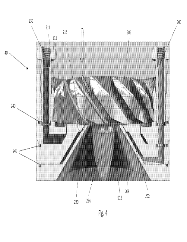
[0041] FIG. 3 is a cross-sectional elevation view of an embodiment of an
atomizer 40 while
FIG. 4 is a partially cutaway elevation view of the atomizer. The atomizer
includes an influent
channel 200, through which influent enters the atomizer 40. The influent
passes along the
channel 200, though the frustoconical space 202, and through a narrower
frustoconical region
203 into a region 204 defined between lower and upper flat surfaces, 206, 208,
respectively.
The influent flows into this region in an inflow direction indicated by arrow
210.
[0042] Simultaneously, air 211 flows through an array of vanes, or vectors,
that impart a
radially inward component as well as a rotational motion to the airflow, as
will be discussed in
greater detail below. The air then proceeds along an annular passage 212
formed between the
lower and upper flat surfaces 206, 208, in an air inflow direction indicated
by arrow 214. The
inflow of air and the inflow of influent meet in a mixing zone 216 that is
radially outward of
the exit of the passage defined by the annular region 203. In an embodiment,
the lower flat
surface 206 includes an annular recess portion (218, best seen in FIG. 7)
extending radially
outward from a radially inner region and extending radially outward past the
annular region
203.
[0043] Because the mixing zone 216 is defined by two substantially flat and
parallel surfaces,
an embodiment may provide for adjustability of the volume of the mixing zone.
Specifically,
9
CA 03214384 2023- 10-3
WO 2023/043487
PCT/US2022/021535
by relative movement of the upper and lower flat surfaces 206, 208, the volume
of the mixing
zone may be increased or decreased, without significant redesign to the
overall size and shape
of the atomizer 40. Such adjustments may allow, for example, to modify a
throughput of the
atomizer, to reduce or eliminate dead zones in flow, to control the
interaction between the
influent flow and the air flow, or other effects that may result from altering
the pressure ratios
in the mixing zone. This differs, for example, from atomizers in which the
mixing zone is
defined by parallel conical or frustoconical surfaces, in that relative
movement of such surfaces
involves a change in angular relationship in addition to the change in volume,
which either
tends to result in unpredictable changes in flows, or requires modifying one
or both of the
surfaces to compensate for the changes in angular relationship.
[0044] A counterflow relationship between the air (flowing with a radially
inward component)
and the influent (flowing with a radially outward component) is established in
the mixing zone
as described above. These counterflows intersect, and where the air and the
influent flows
collide forcefully in the mixing zone, the surface tension of the fluid is
rapidly and forcefully
overcome by the airflow, and atomization of the influent occurs. The resulting
stream of air
mixed with atomized influent is then blown out though a frustoconical exit
region 220, with a
major component in a direction shown by arrow 222.
[0045] The inventor has found that flows through the exit region 220 tend to
include "dead"
spaces in a central portion of the region. These are portions of the region
where airflows are
relatively slower than other portions, which can result in the unwanted
deposition of solids,
often in crystalline form. To reduce this effect, a bulb 224 may be included
in the central region
that occupies the space that would otherwise contain slower airflows. The bulb
224 may be
conical, cylindrical, or, as shown, generally conical with curved sides (for
example, a
paraboloid). The specific shape and volume of the bulb 224 may be determined
empirically,
for example by using flow visualization techniques to determine which regions
tend to have
dead space, or by observing locations where material accumulates.
CA 03214384 2023- 10-3
WO 2023/043487
PCT/US2022/021535
[0046] In an embodiment, the atomizer 40 from time to time has feedwater
injected via
cleaning inlet 230 into its input flow path to clean any deposited solids. The
cleaning feedwater
flows into an annular cleaning water passage 232, and through a narrower
passage into the
region 204 where it flows radially inwardly, passing along through the mixing
zone 216 and
proceeding out through the exit region 220, along a path similar to that of
the atomized influent.
[0047] The cleaning feedwater can remove deposited material, both by
dissolving it, and by
way of mechanical action. Cleaning may be on a schedule or an ad hoc basis in
various
embodiments.
[0048] As may be seen in FIG. 4, an airflow controlling component 900 is
located in a central
portion of the atomizer 40, such that influent flowing through the passages
202, 203 into the
mixing zone 216 meets air flowing through the passage 212 in a controlled and
defined manner.
[0049] In particular, the airflow controlling component 900 includes an array
of vectors or
vanes 902 that are configured to provide a rotational component to the airflow
through the
atomizer. Each vector 902 is angled relative to the axial direction of the
airflow controlling
component 900. Relative to the axial direction, this angle may be about 34 ,
but in general
may lie in a range between about 30 and about 40 , or more particularly, in a
range between
33 and 36 . Optionally, each vector includes a portion 904 on the upstream
side that is curved
or has a different angle from the primary angle of the vector 902_ This curved
portion 904
creates an inlet region 906 that is generally larger than the channel 908
between respective
adjacent vectors. In other words, an upper portion of the channel 908 is wider
than a central
portion thereof.
[0050] Similarly, a portion 910 on the downstream side of each vector 902
likewise includes a
curve or different angle from the primary angle of the vector 902. This
creates an outlet region
912 that is generally larger than the channel 908 between respective adjacent
vectors. That is,
a lower portion of the channel 908 is wider than a central portion thereof. In
principle, the
vectors may be configured such that only one, or both, of the upper and lower
portions of the
11
CA 03214384 2023- 10-3
WO 2023/043487
PCT/US2022/021535
channel 908 is wider than the central portion. The inventor has determined
that, in particular,
the use of a wider lower portion improves the throughput in the mixing zone
216.
[0051] As shown in FIG. 9, the vectors may further include a rounded portion
914 at the
upstream side. This rounding may improve airflow, by reducing sharp corners
and providing
a more streamlined path. Furthermore, each may include a sawtooth or
shouldered portion 916
that can be used to engage corresponding cooperative shoulder structure 918
(see, FIG. 5) in
the wall where the airflow controlling component 900 is supported and held,
thereby holding
it steady in place. In the case that the rounded portion and/or sawtooth
portion 916 are included,
the upper housing member 1000 includes corresponding cooperating structure to
provide
appropriate clearance for airflow therethrough.
[0052] In embodiments, the atomizer may be constructed from a stack of
components, each
formed to cooperate with adjacent components to define the necessary passages.
In this
approach, it may be useful to include grooves in mating surfaces of the
components for holding
respective o-rings 240. An array of fasteners can be used to tightly connect
the components of
the stack. For example, countersunk screws located in holes 242 may be used
for this purpose.
[0053] One example of such a stacked configuration includes a lower component
(600, FIG.
6), a middle component (700, FIG. 7), and an upper component (800, FIG. 8). An
airflow
controlling component (900, FIG. 9) is held radially inward of upward
extending inner ring-
shaped wall 802 of the upper component 800. As seen in FIG. 5, an upper
housing member
1000 has the primary function of surrounding and holding the airflow
controlling component
900. Finally, a top (1100, FIG. 11) may be included to complete the stack.
[0054] As will be appreciated, the structure as shown and described need not
necessarily be
manufactured from a stacked set of components. Rather, the structural features
including the
various channels and passages may be manufactured into either a unitary or
multipart atomizer.
Any particular components as described may be made unitary in any combination.
Thus, the
12
CA 03214384 2023- 10-3
WO 2023/043487
PCT/US2022/021535
middle and upper component may be unitary, or the middle, upper, and airflow
controlling
components may all together be made as a unitary structure.
[0055] In an embodiment of this type, the lower component 600 includes a
frustoconical
portion having a central inner surface 602 that defines the exit region 200 of
the atomizer. An
outer surface 604 of the frustoconical portion, when assembled with the
adjacent middle
component 700, defines the space 202 through which influent flows as shown in
FIG. 3. In
particular, a central inner surface 702 of the middle component 700 includes a
shoulder 704
that provides an offset of the central inner surface 702 relative to the outer
surface 604 of the
lower component 600, cooperating to define the space 202 therebetween.
[0056] In similar fashion, the upper component 800 is configured with
respective shoulders
and offsets on its lower surface 804 such that it cooperates with the middle
component 700 to
define the space 232 for use in the cleaning process.
[0057] In an embodiment, as illustrated in FIG. 10, the airflow controlling
component 900 may
include a central projection 920 on a downstream side of the component. This
projection 920
may be shaped, for example, to provide a surface against which the mixture of
atomized
material and air that comes from the mixing zone is directed downwards and out
towards the
exit region 220. Thus, as seen in FIGS. 3 and 10, the projection includes a
curved surface that
is configured to guide flow that is inwardly radially directed such that it
proceeds in a
downstream direction.
[0058] FIG. 12 shows an atomizer 40 assembled into a portion of a system for
processing water
as described above. The atomizer 40 is connected to an interface 1202 that is
designed to guide
flow from the atomizer to the evaporator/primary condenser 80. The atomizer 40
is connected
to the interface 1202 by a flange 1204 that may be fastened, for example, with
a plurality of
screws (not shown). Also shown are a plenum 1206 through which air flows to
the atomizer
40, and screws 1208 that can be used to adjust the volume of the mixing zone
as discussed
above.
13
CA 03214384 2023- 10-3
WO 2023/043487
PCT/US2022/021535
[0059] In some embodiments, the water purification system can include a
control system (not
shown) to control the flow of air and or water within certain portions of the
system. For
example, the control system can include a set of components such as pressure
sensors and
adjustable valves to monitor and/or control the flow rate and pressure of air
from the blower.
Similarly, the flow rate, pressure, and/or saturation of the solution entering
or exiting the
atomizer assembly and/or the evaporator assembly can be controlled. In this
manner, the
saturation level of the mixture can be monitored and controlled. The term
"sensor" can be
understood to be a single sensor, an array of sensors having separate
functions, and/or a
multifunction unitary sensor.
[0060] The sensors may be monitored and controlled using a controller, which
may be, for
example, a programmable general purpose computer or a purpose-designed
computer. In an
embodiment, a first sensor monitors temperature, pressure, and flow rate at
the evaporator
input, while a second sensor monitors temperature and pressure of the
evaporator output.
Additional sensors are provided to monitor temperature and pressure of the
blower input and
output, to monitor temperature and pressure of the condenser input and output,
and to monitor
the temperature of the first heat exchanger liquid input and output. Likewise,
sensors may be
provided to monitor temperature of the vapor output of the second heat
exchanger and to
monitor temperature of the second heat exchanger liquid input and output.
[0061] In an embodiment, water may be injected into the blower output to cool
it and re-
saturate the air before going to the primary condenser/secondary evaporator,
though this is not
required. Likewise, the blower itself produces heat, and that heat can be used
as part of the
energy involved in operating the system by passing the output of the blower
through a heat
exchanger (intercooler, as noted above).
[0062] A method of treating water may include using an atomizer in accordance
with
any of the foregoing embodiments to atomize water in a water treatment system.
Likewise, a water treatment system may include an atomizer in accordance with
any
of the foregoing embodiment.
14
CA 03214384 2023- 10-3
WO 2023/043487
PCT/US2022/021535
[0063] Embodiments of the atomizer described herein may find use, for example,
in systems
of the type described in U.S. Pat. App. No. 17/274,006, filed March 5, 2021,
herein
incorporated by reference in its entirety. As in the system described therein,
one or both of the
evaporators may be, for example, shell and tube heat exchangers. In a shell
and tube heat
exchanger, one fluid flows through the tubes while the other flows on the
shell side of the tubes.
Heat flows through the tube walls, so the material should be one that is a
good conductor of
heat. Additionally, it may be useful to use a material that is corrosion
resistant and have
sufficient strength to maintain pressure differentials between the zones of
the exchanger and
between the shell and the ambient pressure. Metals, including copper, copper
alloys, stainless
steels, aluminum, and nickel alloys may be used, for example. The use of a
large number of
tubes provides a large surface area for heat transfer.
[0064] The description of the present application has been presented for
purposes of illustration
and description, and is not intended to be exhaustive or limited to the
invention in the form
disclosed. Many modifications and variations will be apparent to those of
ordinary skill in the
art. For example, aspects of each embodiment may be combined with aspects of
each other
embodiment. As one example, the optional structure for providing adjustability
may be used
in any of the depicted embodiments, or may be omitted. Likewise, the stacked
component
approach to assembly is not required, but other manufacturing techniques may
be used to create
the atomizer having the relevant passages and plenums. Various embodiments of
separators
and heat exchangers may find use in each of the different described
embodiments. The specific
placement of pumps may vary from upstream to downstream of the tanks with
which they
interact. The embodiments were chosen and described in order to best explain
the principles
of the invention, the practical application, and to enable others of ordinary
skill in the art to
understand the invention for various embodiments with various modifications as
are suited to
the particular use contemplated. Unless otherwise specified, the term "about"
should be
understood to mean within - 10% of the nominal value. As used in this
specification, the
singular forms "a," "an" and "the" include plural referents unless the context
clearly dictates
otherwise. Thus, for example, the term "a member" is intended to mean a single
member or a
CA 03214384 2023- 10-3
WO 2023/043487
PCT/US2022/021535
combination of members, "a material" is intended to mean one or more
materials, or a
combination thereof. The term "substantially" may be understood to encompass a
variation of
10%, for example.
[0065] While the term zero liquid discharge is used herein, it should be
understood that in some
implementations, the waste stream may include some amount of liquids. That is,
as the term
is used in the art, it may encompass near-zero liquid discharge or minimal
liquid discharge, and
the solids discharged may include some amount of liquid moisture. Likewise, a
ZLD process
may include, in embodiments, a filter press or centrifuge process to remove
residual moisture
from the precipitated solid waste after processing with the system.
[0066] While common reference numerals are used to denote commonly named
components,
this should not be taken to mean that those components must be identical. In
practice, they
will be designed in accordance with operational considerations of the various
systems,
including, for example, flow rates, type of influent, concentration of
contaminants, and the like.
So, for example, while each system described includes a primary
condenser/secondary
evaporator, those may, in practice, take somewhat different forms.
[0067] As used in this specification, the term "fluid" may be understood to
refer to a liquid, a
gas, a liquid including solids which may be in solution or entrained, or
combinations thereof.
The terms "atomize" and "vaporize" describe the process of reducing a liquid
or solution into
a series of tiny particles, droplets and/or a fine spray. For example, as used
herein, a device or
component configured to atomize a liquid and/or produce and atomized flow of a
liquid can be
any suitable device or component that reduces and/or "breaks" the liquid into
a series of tiny
particles and/or a fine spray.
[0068] The descriptions above are intended to be illustrative, not limiting.
Thus, it will be
apparent to one skilled in the art that modifications may be made as described
without departing
from the scope of the claims set out below.
16
CA 03214384 2023- 10-3