Note: Descriptions are shown in the official language in which they were submitted.
WO 2022/216384
PCT/US2022/018215
PATIENT POSITIONING SYSTEMS AND METHODS
CROSS-REFERENCE TO RELATED APPLICATIONS
100011 This application claims the benefit of and priority to U.S. Provisional
Patent
Application No. 63/173,171, filed on April 9, 2021, entitled "Patient
Positioning Device and
Method of Use Thereof,- U.S. Provisional Patent Application No. 63/240,539,
filed on
September 3, 2021, entitled "Patient Positioning Systems and Methods," and
U.S. Provisional
Patent Application No. 63/277,383, filed on November 9, 2021, entitled
"Patient Positioning
Systems and Methods," all of which are hereby incorporated by reference
herein.
BACKGROUND
[0002] The present disclosure generally relates to an apparatus, system, and
method for
supporting a patient for a medical procedure, and in particular for supporting
a patient when
positioned in a non-parallel or tilted position, such as in the Trendelenburg
position.
[0003] When a patient is unconscious, disabled, or otherwise unable to move on
their own, it
is often difficult to retain the patient in a consistent position so as to
keep the patient safe and
out of the way of operating room staff For example, when patients undergo
surgery, it is
often necessary to tilt the operating table on which the patient rests in
order to gain access to
the surgical area. Tilting the operating table results in the patient laying
supine at an angle,
wherein the patient's feet may be above the patient's head or the patient's
head may be above
the patient's feet One such common positioning in surgery is the Trendelenburg
position,
where the patient is tilted at 15 to 45 and the patient's feet are elevated
above the patient's
head. When the patient is in the Trendelenburg position (or the reverse
Trendelenburg
position (i.e., the patient's feet are down and their head is elevated), the
lithotomy position
(i.e., the patient is on their back with their legs flexed), the High Fowler's
position (i.e., the
patient is sitting with the upper half of their body upward), or laterally
tilted, etc.), it is
difficult to maintain the patient's position upon the operating table.
[0004] Furthermore, a patient's arms often need to be adducted during
surgeries in order to
keep the patient's arms safe from cuts, burns, and generally out of the way.
However, in
-1-
CA 03214576 2023- 10-4
WO 2022/216384
PCT/US2022/018215
keeping the patient's arms safe and secure, doctors often lean against the
patient's arms while
operating, which may subject the patient to related-pressure injuries or
potential nerve
damage.
100051 The present disclosure seeks to overcome certain of these limitations
and other
drawbacks of existing devices, systems, and methods, and to provide new
features not
heretofore available.
SUMMARY
100061 At least one embodiment relates to a method for reprocessing a patient
positing
system, the system comprising inflatable device and a high-friction pad
configured to attach
to the inflatable device. The method includes removing the high-friction pad
from the
inflatable device, at least one of cleaning or sterilizing the inflatable
device, and providing a
replacement for at least one component of the patient positioning system.
100071 Another embodiment relates to a method of preparing a patient
positioning system for
reuse. The method includes obtaining a used inflatable device, the inflatable
device
comprising at least one connection mechanism for coupling to a high-friction
pad, and
providing a replacement high-friction pad to replace an original high-friction
pad that was
used with the inflatable device.
100081 Another embodiment relates to a patient support system. The patient
support system
comprises a high-friction pad having a top surface and a bottom surface, where
the top
surface is configured to support a patient and the bottom surface is
configured to face a
support structure. The high-friction pad also includes at least one arm wrap
including a foam
section, where the at least one arm wrap is configured to secure an arm of the
patient, and at
least one strap, where the at least one strap is configured to couple the high-
friction pad to the
support structure.
100091 Another embodiment relates to a method, the method including providing
a patient
positioning system. The patient positioning system includes a high-friction
pad having a top
surface and a bottom surface, the top surface configured to support a patient
and the bottom
surface configured to face a support structure. The high-friction pad also
includes at least one
-2-
CA 03214576 2023- 10-4
WO 2022/216384
PCT/US2022/018215
arm wrap including a foam section, the at least one arm wrap configured to
secure an arm of
the patient, and at least one strap, the at least one strap configured to
couple the high-friction
pad to the support structure. The method further includes placing the high-
friction pad on the
support structure, such that the bottom surface faces the support structure,
and attaching the
high-friction pad to the support structure using the at least one strap.
100101 This summary is illustrative only and should not be regarded as
limiting.
BRIEF DESCRIPTION OF THE FIGURES
100111 The disclosure will become more fully understood from the following
detailed
description, taken in conjunction with the accompanying figures, wherein like
reference
numerals refer to like elements, in which:
100121 FIG. 1 is a top view of a patient positioning system, according to an
exemplary
embodiment.
100131 FIG. 2 is a top view of an inflatable device of the patient positioning
system of FIG. 1,
according to an exemplary embodiment.
100141 FIG. 3 is a bottom view of a high-friction pad of the patient
positioning system of
FIG. 1, according to an exemplary embodiment.
100151 FIG. 4 is a partially exploded cross-sectional end view of a high-
friction pad of the
patient positioning system of FIG. 1, according to an exemplary embodiment.
100161 FIG. 5 is a top view of a high-friction pad of the patient positioning
system of FIG. 1,
according to another exemplary embodiment.
100171 FIG. 6 is a top view of the high-friction pad of the patient
positioning system of FIG.
5, according to an exemplary embodiment.
100181 FIG. 7 is a top view of the high-friction pad of FIGS. 5-6, according
to an exemplary
embodiment.
-3 -
CA 03214576 2023- 10-4
WO 2022/216384
PCT/US2022/018215
100191 FIG. 8 is a bottom view of the high-friction pad of FIGS. 5-7,
according to an
exemplary embodiment.
100201 FIG. 9 is a top view of a portion of a high-friction pad of the patient
positioning
system of FIG. 1, according to an exemplary embodiment.
100211 FIG. 10 is a top view of the patient positioning system of FIG. 1,
according to an
exemplary embodiment.
100221 FIG. 11 is another top view of the patient positioning system of FIG.
1, according to
an exemplary embodiment.
100231 FIG. 12 is a cross-sectional end view of a body pad of the patient
positioning system
of FIG. 1, according to an exemplary embodiment.
100241 FIG. 13 is atop view of a chest strap of the patient positioning system
of FIG. 1,
according to an exemplary embodiment.
100251 FIG. 14 is a view of the patient positioning system of FIG. 1 in use
with a patient,
according to an exemplary embodiment.
100261 FIG. 15 is another view of the patient positioning system of FIG. 1 in
use with a
patient, according to an exemplary embodiment.
100271 FIG. 16 is another view of the patient positioning system of FIG. 1 in
use with a
patient, according to an exemplary embodiment.
100281 FIG. 17 is a view of positioning a patient with the patient positioning
system of FIG.
1, according to an exemplary embodiment.
100291 FIG. 18 is another view of positioning a patient with the patient
positioning system of
FIG. 1, according to an exemplary embodiment.
-4-
CA 03214576 2023- 10-4
WO 2022/216384
PCT/US2022/018215
DETAILED DESCRIPTION OF THE DRAWINGS
[0030] Before turning to the figures, which illustrate certain exemplary
embodiments in
detail, it should be understood that the present disclosure is not limited to
the details or
methodology set forth in the description or illustrated in the figures. It
should also be
understood that the terminology used herein is for the purpose of description
only and should
not be regarded as limiting.
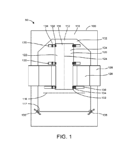
[0031] Referring to FIG. 1, a patient positioning system 50 is shown,
according to an
exemplary embodiment. As shown in FIG. 1, the patient positioning system 50
includes an
inflatable patient support device 102 (hereinafter, "inflatable device" 102)
and a high-friction
pad 104. The high-friction pad 104 is shown lying on the inflatable device
102, with the
inflatable device 102 lying on a support structure 100.
100321 As shown in FIGS. 1-2, the support structure 100 includes a support
surface 110. The
support surface 110 (or support structure 100) may be a bed, gurney,
stretcher, cot, operating
table, or other support suitable for medical and/or patient care use (e.g.,
for supporting a
patient in a supine or other position). The support structure 100, and
corresponding support
surface 110, are not shown in detail, but may generally include other known
features of
medical support for patient care use (e.g., a frame, the support structure 100
supported by the
frame, the support structure 100 including a head, a foot, opposed sides or
edges, etc.).
Similarly, the support structure 100 may also include other medical components
known in the
art (e.g., bed sheets, pillows, blankets, additional sheets, etc.). In some
embodiments, the
support structure 100 is adjustable, such that the support structure 100 (and
the support
surface 110) may be raised, lowered, positioned in an incline, positioned in a
decline, etc. In
an exemplary embodiment, the support structure 100 (and the support surface
110) is/are a
monolithic structure; however, in other embodiments the support structure 100
(and the
support surface 110) comprise a plurality of sections that are coupled (e.g.,
hingedly, slidably,
rotatably, etc.) along an interface (e.g., a break line, etc.). For example,
the support structure
100 (and the support surface 110) may include a first section for supporting a
portion of the
patient (e.g., upper body, mid-section, etc.), and a second section coupled to
the first section,
which is configured to move (hingedly lower, slidably lower, hingedly raise,
pivot, etc.)
-5-
CA 03214576 2023- 10-4
WO 2022/216384
PCT/US2022/018215
relative to the first section and/or position another portion of the patient
(e.g., lower body,
hips, legs, feet, etc.). It should be understood that the patient positioning
system 50, and the
components thereof, may be used with different support structures 100,
inflatable devices
102, high-friction pads 104, etc., and may be used to transfer a patient from
one support
structure 100 to another, or from one support structure 100 to a different
support structure
100.
100331 As shown in FIGS. 1-2, the inflatable device 102 includes a top surface
112, a bottom
surface 114 (not shown), an alignment indicia shown as alignment line 116, and
inflation
ports 117. In an exemplary embodiment, the inflatable device 102 is positioned
on the
support structure 100. More specifically, the inflatable device 102 may be
positioned on the
support surface 110, such that the bottom surface 114 of the inflatable device
102 is
supported by the support surface 110. Although the inflatable device 102 may
be in contact
with the support surface 110, the inflatable device 102 may include one or
more structures
located between the bottom surface 114 and the support surface 110. Further,
in some
embodiments the inflatable device 102 includes inflation ports 117 (e.g.,
configured to couple
to inflation socks 106) for inflating the inflatable device 102. In an
exemplary embodiment,
the inflatable device 102 is flexible and foldable when in the non-inflated
state, and is
generally rectangular in shape, with a chamfered edge and peripheral edges. In
other
embodiments, the inflatable device 102 is another suitable shape, including
different shapes
with varying degrees of symmetry (e.g., rectangular with no chamfered edges,
rectangular
with rounded edges, rounded, etc.). In an exemplary embodiment, the inflatable
device 102 is
approximately 50 inches in length; however, in other embodiments the
inflatable device 102
is longer or shorter.
100341 As shown in FIGS. 1-2, the alignment line 116 is provided near a bottom
portion of
the top surface 112 of the inflatable device 102, and is configured to aid in
aligning
components of the patient positioning system 50. For example, the alignment
line 116 may
aid a user in aligning the inflatable device 102 relative to the support
structure 100 (e.g.,
aligning the alignment line 116 at the break line of the support structure
100, where a second
section of the support structure 100 pivots relative to a first section,
etc.). In some
embodiments, the alignment line 116 is configured to aid a user in aligning
the high-friction
-6-
CA 03214576 2023- 10-4
WO 2022/216384
PCT/US2022/018215
pad 104 relative to components of the inflatable device 102 (e.g., a
connection area, a
connection strip, etc.). In other embodiments, the alignment line 116 is
configured to aid a
user in aligning other components of the patient positioning system 50 (e.g.,
a body pad, etc.)
relative to the support structure 100, the inflatable device 102, and/or the
high-friction pad
104. It should be understood that while the alignment indicia is shown as the
alignment line
116, the indicia may be another suitable indicator (e.g., a bar, hatch, cross,
color, dot, etc.),
and/or positioned at any suitable location on the inflatable device 102 (e.g.,
head, side,
middle, medial, lateral, etc. portion), such that the indicia may aid in
positioning components
of the patient positioning system 50.
100351 As shown in FIG. 1, the high-friction pad 104 includes a top pad
surface 118, a
bottom pad surface 119 (not shown), a first pad section 120, a second pad
section 122, a
perforated separator 124, arm wraps 126 (including foam section(s) 128), and
straps 130. In
an exemplary embodiment, the high-friction pad 104 is positioned on the
inflatable device
102, and supports to a patient while the inflatable device 102 is used for a
number of different
medical and/or patient care uses, as discussed below.
100361 As shown in FIG. 1, the high-friction pad 104 is smaller than the
inflatable device 102
(e.g., less than 50 inches in length), and is positioned on the inflatable
device 102 above the
alignment line 116 (i.e., not covering the alignment line 116) so as to
provide support to a
portion of the patient's body (e.g., upper body, mid-section, etc.). In other
embodiments, the
high-friction pad 104 is a similar size as the inflatable device 102 (e.g.,
around 50 inches in
length), and/or is positioned at another position relative to the alignment
line 116 (e.g., on top
of, at, below, etc.). In an exemplary embodiment, the high-friction pad 104
has a thickness of
approximately 1.0 inch +/- 0.125 inch; however, in other embodiments the high-
friction pad
104 is as thick as 2.0 inches or as thin as 0.125 inch. The high-friction pad
104 may be made
of foam (e.g., open cell foam, gel imprinted polyether foam, etc.), cushion,
and/or any other
suitable material configured to cushion, secure, and/or support the patient.
For example, the
high-friction pad 104 may be made of a material with a high coefficient of
friction so as to
increase the friction between the patient and the inflatable device 102. In
some embodiments,
the top pad surface 118 and/or the bottom pad surface 119 include only
portion(s) of the
surfaces 118 and/or 119 with high coefficients of friction In other
embodiments, the top pad
-7-
CA 03214576 2023- 10-4
WO 2022/216384
PCT/US2022/018215
surface 118 and the bottom pad surface 119 have the same or different
coefficients of friction.
The high-friction pad 104 may be made of material with specific properties
suitable for
certain medical and/or patient care uses (e.g., fluid absorbent, low-lint
properties, disposable,
barrier to fluid passage on one side, breathable on another side, the same or
different
coefficients of friction on either side, etc.). The high-friction pad 104 may
be configured
differently in different embodiments.
100371 As shown in FIG. 1, the high-friction pad 104 includes the first pad
section 120 and
the second pad section 122, separated by the perforated separator 124. The
perforated
separator 124 may be positioned along the central portion of the high-friction
pad 104 (e.g.,
between the first pad section 120 and the second pad section 122). In an
exemplary
embodiment, the high-friction pad 104 may be ripped, cut, or otherwise torn
along the
perforated separator 124 to help move or reposition a patient (e.g., to remove
the first pad
section 120, the second pad section 122, and/or both), as discussed below.
100381 Referring still to FIG. 1, the high-friction pad 104 also includes arm
wraps 126, each
having at least one foam section 128. In an exemplary embodiment, the arm
wraps 126 are
fully integrated with the high-friction pad 104, and are coupled (e.g.,
fastened, sewn, etc.) to
the high-friction pad 104 by stitching, hook/loop fasteners, and/or another
suitable fastening
mechanism, as discussed below. According to an exemplary embodiment, the arm
wraps 126
are formed of a material having a fastening feature (e.g., a loop material,
hook material, etc.)
at a portion of the arm wraps 126 (e.g., at a first surface, a second surface,
a portion of a first
surface, etc.). In some embodiments, the arm wraps 126 are also formed of a
suitable flexible
material (e.g., nylon, etc.). According to an exemplary embodiment, the arm
wraps 126 are
configured to secure a patient's arms in place when the high-friction pad 104
is in use with
the patient. For example, the patient's arms may be adducted using the arm
wraps 126 during
a surgical procedure in order to prevent burns, cuts, pressure injuries,
pinching, and/or keep
the patient's arms out of the way of operating room staff Further, the
patient's arms (or other
anatomy) may be secured, using the arm wraps 126, when the patient is
Trendelenburg
position, the reverse Trendelenburg position, the Lithotomy position, the
Lateral Tilt position,
and/or any other specific position needed for a surgical procedure and/or
patient care use. In
some embodiments, the arm wraps 126 are positioned at a portion of the high-
friction pad
-8-
CA 03214576 2023- 10-4
WO 2022/216384
PCT/US2022/018215
104 that support a patient's torso, such that the patient's arms lie near (or
within) the arm
wraps 126.
[0039] According to an exemplary embodiment, the arm wraps 126 also include at
least one
foam section 128 configured to cushion, secure, protect, and/or support the
patient. In an
exemplary embodiment, the foam section 128 is integrated with the arm wraps
126 via a
suitable manufacturing technique (e.g., lamination, etc.). The foam section
128 may be
formed of the same or similar material as the high-friction pad 104 (e.g.,
open cell foam, gel
imprinted polyether foam, etc., cushion, and/or any other material). According
to an
exemplary embodiment, the foam section 128 is approximately 25 inches in
length (e.g., a
length extending in a direction substantially parallel to the perforated
separator 124, etc.),
and/or approximately 10 inches in width (e.g., a width extending in a
direction substantially
perpendicular to the perforated separator 124), and is configured to cover the
patient's arm,
hand, and/or fingers when the patient's arm is within the arm wrap 126. In
this regard, the
foam section 128 may keep the patient's arms comfortable, safe, and secure
during surgical
procedures. For example, the foam section 128 may reduce the potential
pressure applied to
the patient's arms during surgical procedures (e.g., if a surgeon leans on the
patient's arms),
and may prevent potential pressure-related injuries, pinching, and/or nerve
damage. It should
be understood that while the foam section 128 is described as haying certain
lengths and/or
widths, the foam section 128 may be another suitable length (e.g., 20, 22.5,
27.5, 30, etc.
inches) and/or width (e.g., 7.5, 8, 8.5, 9, 9.5, 10.5, 11, 11.5, 12, etc.
inches), such that the
foam section 128 is configured to cover (partially, completely, etc.) the
patient's arm, hand,
and/or fingers when the patient's arm is within the arm wrap 126.
[0040] As shown in FIG. 1, the high-friction pad 104 also includes straps 130.
The straps 130
may be coupled with the high-friction pad 104 (and/or any of its component
parts), and may
be configured to secure the high-friction pad 104, for example, to the support
structure 100,
the inflatable device 102, etc. The straps 130 may be formed of any suitable
material (e.g.,
fastening material, flexible material, etc.), and may be configured to fasten
to components of
the high-friction pad 104 (e.g., the strap 130 itself, other straps 130, the
arm wraps 126, the
foam section 128, etc.). For example, the straps 130 may be formed of a
combination
hook/loop material at least at a portion of the straps 130 (e.g., a
combination hook/loop
-9-
CA 03214576 2023- 10-4
WO 2022/216384
PCT/US2022/018215
material on a first side, or a hook material on a first side and a loop
material on a second side,
etc.), and may be configured to loop around the support structure 100 and
fasten to itself
(e.g., strap 130 via the hook/look material, etc.), as discussed below. As
shown in FIG. 1, the
high-friction pad 104 includes three straps 130 on each lateral side of the
high-friction pad
104. In an exemplary embodiment, the straps 130 on a first lateral side are
aligned with straps
130 on the opposing lateral side, thereby forming pairs of aligned straps 130.
In other
embodiments, the high-friction pad 104 includes any suitable number straps 130
(e.g., one,
two, four, five, six, seven, eight, nine, ten, etc.), and/or the straps 130
are positioned in any
suitable arrangement along the high-friction pad 104 (e.g., along the head,
foot, arm wraps
126, etc.).
100411 As shown in FIG. 1, the straps 130 are coupled to the high-friction pad
104 by
stitching 132. According to an exemplary embodiment, the stitching 132
integrates (e.g.,
sews, fastens, couples, fixes, etc.) the straps 130 to the high-friction pad
104. In an exemplary
embodiment, the stitching 132 is a double-boxed stitch; however, in other
embodiments, the
stitching 132 is another suitable type of stitching (e.g., zigzag, straight
stretch, stretch knit,
closed overlock, honeycomb, etc.). In yet other embodiments, the stitching 132
is another
suitable type of coupling (e.g., hook/loop fasteners, adhesives, etc.)
configured to couple the
straps 130 to the high-friction pad 104.
100421 Also shown in FIG. 1, the high-friction pad 104 includes buckles 134.
According to
an exemplary embodiment, the buckles 134 are positioned along a lateral side
(e.g., an edge)
of the high-friction pad 104 (e.g., at the straps 130, the stitching 132,
etc.), and are configured
to receive (e.g., loop, hook, etc.) the straps 130 through the opening in the
buckle 134. In
some embodiments, the buckles 134 are coupled to other components of the high-
friction pad
104 (e.g., the straps 130, the stitching 132, etc.), and/or are positioned at
other suitable
positions at the high-friction pad 104 (e.g., along the head, foot, etc.). As
discussed briefly
above, in an exemplary embodiment the straps 130 are configured to loop around
anchors
(e.g., under an anchor on the support structure 100, an external rail, etc.),
pass through the
buckles 134 (e.g., loop through, hook around, etc.), and couple the strap 130
to itself (e.g., via
a hook/loop connection, etc.). In other embodiments, the straps 130 and/or the
buckles 134
comprise other fastening components (e.g., snaps, hooks, hook and loop
fasteners, etc.),
-10-
CA 03214576 2023- 10-4
WO 2022/216384
PCT/US2022/018215
and/or are configured to couple to other components of the high-friction pad
104 (e.g., the
straps 130, the buckles 134, etc.).
100431 Referring now to FIG. 2, a top view of the inflatable device 102 of the
patient
positioning system 50 is shown, according to an exemplary embodiment. As
mentioned with
regard to FIG. 1, the inflatable device 102 includes the top surface 112, the
bottom surface
114 (not shown), the indicia shown as alignment line 116, and the inflation
ports 117 (e.g.,
configured to couple to the inflation socks 106). Further, the inflatable
device 102 also
includes an inflatable body 210, a plurality of connection areas 212, and a
plurality of
connection strips 214.
100441 In an exemplary embodiment, the inflatable body 210 defines an internal
cavity and is
configured to be inflated with air or another gaseous substance (e.g., via the
inflation ports
117 using the inflation socks 106). The inflatable body 210 may be defined by
the top surface
112 (e.g., a top sheet) and the bottom surface 114 (e.g., a bottom sheet),
such that the surfaces
112 and 114 define the internal cavity to be inflated. In some embodiments,
the surfaces 112
and 1114 are made of materials that have properties that are desirable for a
particular
application (e.g., properties favorable for breathability, durability, imaging
compatibility,
flammability, biocompatibility, pressure distribution profile, heat
transmission, electrical
conductivity, cleaning properties, etc.). In other embodiments, the top
surface 112 includes at
least a portion of the surface formed from a high-friction or gripping
material (e.g., knitted
material, polyester, polyurethane coating, etc.), and the bottom surface 114
includes at least a
portion of the surface formed from a low-friction material (e.g., sheet
material). In yet other
embodiments, both surfaces 112 and 114 are made from a low-friction material.
The
inflatable device 102 may be configured as described in U.S. Patent
Application Publication
Number US2018/0353360, entitled "Patient Positioning and Support System- filed
on June
13, 2018, which is hereby incorporated by reference in its entirety.
100451 As shown in FIG. 2, the inflatable body 210 also includes one or more
inflation-
limiting structures (e.g., the plurality of connection areas 212), which are
configured to create
a specific inflated shape for the inflatable device 102. In general, the
inflation-limiting
structures are positioned between the surfaces 112 and 114 in order to limit
the amount the
-11 -
CA 03214576 2023- 10-4
WO 2022/216384
PCT/US2022/018215
surfaces 112 and 114 can move apart during inflation (e.g., while the
inflatable device 102 is
inflating). For example, the plurality of connection areas 212 may be
positioned between the
top surface 112 and the bottom surface 114, and form an inflation-limiting
structure. Further,
the plurality of connection areas 212 may be connected to the surfaces 112 and
114 in a
variety of configurations (e.g., one or more concentric circles, three
concentric circles,
squares, rectangles, and/or any combination, etc.) and/or connection methods
(e.g. stitching,
adhesive, sealing, and/or any combination, etc.). In an exemplary embodiment,
the inflatable
device 102 fully inflated has a shape that is defined by the configuration of
the inflatable
device 102, as well as, the configuration of the plurality of connection areas
212.
100461 Referring still to FIG. 2, the inflatable body 210 also includes a
plurality of
connection strips 214. In an exemplary embodiment, the connection strips 214
are made of
hook and/or loop fasteners, and are configured to attach the bottom pad
surface 119 (of the
high-friction pad 104) to the top surface 112 (of the inflatable device 102),
as discussed
below. In some embodiments, the connection strips 214 are formed of different
fastening
mechanisms (e.g., strings, snaps, hooks, loops, etc.), and/or are configured
to attach the top
surface 112 (of the inflatable device 102) to other components of the patient
positioning
system 50 (e.g., a bottom surface of a body pad, etc.). In an exemplary
embodiment, the
connection strips 214 extend substantially the length of the inflatable body
210 (e.g., from the
chamfer edge near the head of the inflatable body 210, along an edge, and to
the foot). In
other embodiments, the connection strips 214 do not extend the full length of
the inflatable
body 210, and/or have other configurations (e.g., extend along the head, foot,
side edges,
and/or any combination thereof). In yet other embodiments, the inflatable body
210 (and/or
the inflatable device 102) also includes additional anchoring mechanisms
(e.g., additional
anchors, hooks, loops, straps, etc.), which allow the inflatable device 102 to
further attach to
the high-friction pad 104 (e.g., via the straps 130), and/or other components
(e.g., the support
structure 100, external rails, etc.).
100471 Referring now to FIG. 3, a bottom view of the high-friction pad 104 of
the patient
positioning system 50 is shown, according to an exemplary embodiment. In an
exemplary
embodiment, the high-friction pad 104 is the high-friction pad of FIG. 1. As
shown in FIG. 3,
-12-
CA 03214576 2023- 10-4
WO 2022/216384
PCT/US2022/018215
the bottom pad surface 119 of the high-friction pad 104 includes counterpart
connection
strips 302.
[0048] According to an exemplary embodiment, the counterpart connection strips
302 are
coupled to the bottom pad surface 119 via the stitching 132. In an exemplary
embodiment,
the counterpart connection strips 302 are made of hook and/or loop fasteners,
and are
configured to selectively couple the plurality of connection strips 214 of the
inflatable body
210 (i.e., connect the bottom pad surface 119 of the high-friction pad 104 to
the top surface
112 of the inflatable device 102). For example, the counterpart connection
strips 302 may be
made of opposite hook and/or loop fasteners relative to the connection strips
214 (e.g., the
counterpart connection strips 302 are made of a second member of a hook/loop
fastener to
couple a first member of the hook/loop fastener of the connection strips 214).
Like the
connection strips 214, in an exemplary embodiment the counterpart connection
strips 302
extend the length of the high-friction pad 104 (e.g., from the head of the
high-friction pad
104, down an edge, and to the foot). In some embodiments, the counterpart
connection strips
302 are also coupled to the straps 130 (e.g., via the stitching 132). In other
embodiments, the
counterpart connection strips 302 are made of another suitable fastener (e.g.,
strings, snaps,
hooks, loops, etc.), do not extend the full length of the high-friction pad
104, and/or have
other configurations (e.g., extend along the head, foot, side edges, or any
combination
thereof). In yet other embodiments, the arm wraps 126 also include a
counterpart connection
fastener (e.g., a hook, a loop, a hook/loop opposite the counterpart
connection strips 302,
etc.), such that the arm wraps 126 couple (e.g., fasten, etc.) the counterpart
connection strips
302, as discussed below.
[0049] Referring now to FIG. 4, a partially exploded cross-sectional end view
of the high-
friction pad 104 of the patient positioning system 50 is shown, according to
an exemplary
embodiment. In an exemplary embodiment, the high-friction pad 104 is the high-
friction pad
104 of FIGS. 1 and 3.
[0050] As shown in FIG. 4, the high-friction pad 104 also includes arm wrap
anchors 402.
According to an exemplary embodiment, the arm wrap anchors 402 are fully
integrated with
the high-friction pad 104 (e.g., coupled, adhered, sewn, attached, etc.), and
are positioned at a
-13 -
CA 03214576 2023- 10-4
WO 2022/216384
PCT/US2022/018215
lateral side (e.g., an edge) of the high-friction pad 104. The arm wrap
anchors 402 may be
formed of any suitable fastening material, and may be configured to couple
(e.g., fasten, etc.)
the high-friction pad 104 and/or the arm wraps 126. In an exemplary
embodiment, the arm
wrap anchors 402 are hooks (e.g., a hook portion of a hook/loop fastener,
etc.), and are
configured to couple a portion of the arm wrap 126, so as to secure the arm
wrap 126 to the
high-friction pad 104. In some embodiments, the arm wrap anchors 402 are
positioned in
another suitable arrangement along the high-friction pad 104, include a
plurality of arm wrap
anchors 402, and/or are formed of another suitable fastening component (e.g.,
snap, clip,
buckle, etc.).
100511 As shown in FIG. 4, the arm wrap 126 also includes a first arm wrap
surface 404. In
an exemplary embodiment, the first arm wrap surface 404 includes (and/or is
formed by) a
loop material (e.g., loops of a hook/loop fastener, etc.), and is configured
to couple
components of the high-friction pad 104 (e.g., the arm wrap anchors 402, the
counterpart
connection strips 302, etc.). As shown in FIG. 4, the first arm wrap surface
404 is configured
to couple (e.g., fasten, connect, etc.) the arm wrap anchor 402 at a first
portion of the first arm
wrap surface 404 (e.g., via the loops of the first arm wrap surface 404 and
the hooks of the
arm wrap anchor 402, etc.). The arm wrap 126 may be folded (e.g., bent,
crimped, etc.), so as
to orient the first portion of the first arm wrap surface 404 in a first
direction (e.g., vertically
upward), and a second portion of the first arm wrap surface 404 in a second
direction (e.g.,
vertically downward). The counterpart connection strip 302 may then positioned
so as to
sandwich the first arm wrap surface 404 between the arm wrap anchor 402 (to
which it is
engaged) and the counterpart connection strip 302 (for coupling to the
inflatable device 102),
such that arm wrap 126 may be integrated with the high-friction pad 104. In an
exemplary
embodiment, the arm wrap anchors 402, the first arm wrap surface 404, and/or
the
counterpart connection strip 302 is/are reinforced (e.g., via stitching,
stitching 132, etc.) at a
position of the high-friction pad 104 where the arm wrap anchors 402, the
first arm wrap
surface 404, and/or the counterpart connection strip 302 is/are coupled. In
some
embodiments, the arm wrap anchors 402, the first arm wrap surface 404, and/or
the
counterpart connection strip 302 are reinforced via the stitching 132 at a
position of the high-
friction pad 104 where the straps 130 are integrated with the high-friction
pad 104.
-14-
CA 03214576 2023- 10-4
WO 2022/216384
PCT/US2022/018215
100521 Referring now to FIGS. 5-7, top views of a high-friction pad 104 of the
patient
positioning system 50 is shown, according to another exemplary embodiment. The
components of the high-friction pad 104 of FIGS. 5-7 are similar to components
of the high-
friction pad of FIGS. 1 and 3, and thus, similar reference numerals are used
to refer to similar
components. As shown in FIGS. 5-7, the high-friction pad 104 includes arm
wraps 126 (each
having at least one foam section 128), the straps 130, the stitching 132, and
the buckles 134.
[0053] According to the exemplary embodiment of FIGS. 5-7, the arm wraps 126
are coupled
to the high-friction pad 104 via hook/loop fasteners, and are configured to
selectively
couple/de-couple the high-friction pad 104 so as to be attachable/removable.
In this regard,
the arm wraps 126 may include a material having a fastening feature (e.g.,
hook/loop
material, etc.), which may couple/de-couple a counterpart fastening feature
(e.g., a loop/hook
material, etc.) on the high-friction pad 104, as discussed below.
100541 As shown in FIGS. 5-7, the arm wraps 126 are coupled to a middle
portion of the
high-friction pad 104, such that when the high-friction pad 104 supports a
patient, the
patient's arms lie near (or within) the arm wraps 126. In the exemplary
embodiment shown in
FIGS. 5 and 7, the arm wraps 126 are coupled to a middle (and lower) lateral
portion of the
high-friction pad 104, and extend beyond (e.g., below in a longitudinal
direction) the high-
friction pad 104 and/or the alignment line 116 of the inflatable device 102.
In some
embodiments, the arm wraps 126 are coupled to another portion of the high-
friction pad 104
(e.g., upper, lower, medial, top, bottom, etc.), and/or are oriented in
another configuration
relative to the high-friction pad 104 and/or the inflatable device 102 (e.g.,
extend above the
high-friction pad 104 in a longitudinal direction, extend above the alignment
line 116, etc.).
[0055] As shown in FIGS. 5-7, the arm wraps 126 also include at least one foam
section 128.
According to the exemplary embodiment of FIGS. 5-7, the foam section 128 is
approximately
25-30 inches in length (e.g., a length extending in a direction substantially
parallel to the
perforated separator 124, etc.) and/or approximately 10 inches in width (e.g.,
a width
extending in a direction substantially perpendicular to the perforated
separator 124), and is
configured to completely cover the patient's hand and/or fingers when the
patient's arm is
within the arm wrap 126. In this regard, the foam section 128 may keep the
patient's arms
-15-
CA 03214576 2023- 10-4
WO 2022/216384
PCT/US2022/018215
comfortable, safe, and secure during surgical procedures. It should be
understood that while
the foam section 128 is described as having certain lengths and/or widths, the
foam section
128 may be another suitable length (e.g., 20, 22.5, 25, 27.5, 30, etc. inches)
and/or width
(e.g., 7.5, 8, 8.5, 9, 9.5, 10.5, 11, 11.5, 12, etc. inches), such that the
foam section 128 is
configured to cover (partially, completely, etc.) the patient's hand and/or
fingers when the
patient's arm is within the arm wrap 126.
[0056] As shown in FIGS. 5-7, the high-friction pad 104 also includes straps
130, which are
coupled to the high-friction pad 104 by stitching 132. As discussed above, the
straps 130 may
be configured to secure the high-friction pad 104 to other components of the
patient
positioning system 50 (e.g., to the support structure 100, the inflatable
device 102, etc.).
According to the exemplary embodiment of FIGS. 5-7, the straps also include
the buckles
134. The buckles 134 may be coupled (e.g., fastened, sewn, etc.) to the straps
130, and may
be configured to receive (e.g., loop, hook, etc.) the straps 130 through an
opening in the
buckle 134. In an exemplary embodiment, the buckles 134 are coupled to the
straps 130 a
distance (e.g., 0.5, 1,2, 2.5, 5, etc. inches) from an edge of the high-
friction pad 104 (and/or
the stitching 132, etc.), such that the buckles 134 are easily accessible when
a patient is
positioned on the high-friction pad 104. As discussed above, in other
embodiments, the straps
130 and/or the buckles 134 comprise other fastening components (e.g., snaps,
hooks, hook
and loop fasteners, etc.), are coupled to other components of the high-
friction pad 104 (e.g., a
lateral side of the high-friction pad 104 itself, a connector strip, etc.),
and/or are positioned at
other suitable positions at the high-friction pad 104 (e.g., along the head,
foot, at an edge of
the high-friction pad 104, etc.).
[0057] Referring now to FIGS. 6-7, top views of the high-friction pad 104 of
the patient
positioning system 50 is shown, according to an exemplary embodiment.
According to the
exemplary embodiment of FIGS. 6-7, the arm wraps 126 also include a fastening
strip 612,
which is configured to selectively couple/de-couple the arm wrap 126 to/from
the high-
friction pad 104, such that the arm wraps 126 are attachable/removable.
[0058] According to an exemplary embodiment, the fastening strip 612 is
positioned along a
lateral edge of the arm wrap 126 (e.g., a lateral edge at the medial portion
of the arm wrap
-16-
CA 03214576 2023- 10-4
WO 2022/216384
PCT/US2022/018215
126), and extends substantially the length of the arm wrap 126. The fastening
strip 612 may
be formed of hook and/or loop fasteners, and may be configured to selectively
couple/de-
couple to/from components of the high-friction pad 104. For example, the
fastening strip 612
may be formed of hook/loop fasteners, and may be configured to couple/de-
couple
counterpart loop/hook fasteners of a counterpart fastening strip 812 (shown in
FIG. 8) of the
high-friction pad 104. In the exemplary embodiment shown in FIG. 6, the
fastening strip 612
is coupled to the counterpart fastening strip 812, such that the arm wrap 126
is positioned at a
middle (and lower) lateral portion of the high-friction pad 104. In some
instances, a user may
want to remove the arm wrap 126 (e.g., for cleaning, transporting, etc.)
and/or reposition the
arm wrap 126 (e.g., for a different procedure, patient position, etc.). In
this regard, and as
shown in FIG. 7, the fastening strip 612 may de-couple the counterpart
fastening strip 812 of
the high-friction pad 104, and the arm wrap 126 may be removed and/or
repositioned. It
should be understood that the fastening strip 612 may be formed of different
fastening
mechanisms (e.g., strings, snaps, hooks, loops, etc.), may be positioned at
other suitable
locations along the arm wrap 126 (e.g., a bottom edge, top surface, bottom
surface, only a
portion of a lateral edge, etc.), and/or may be configured to couple/de-couple
other
components of the patient positioning system 50.
100591 In some embodiments, the fastening strip 612 is formed of a hook/loop
fastener on a
first surface and an opposite loop/hook fastener on a second surface, such
that the fastening
strip 612 is configured to couple/de-couple components on the first surface
and/or the second
surface. For example, the fastening strip 612 may be formed of a hook fastener
on the first
surface, and a loop fastener on the second surface. The fastening strip 612
may further be
configured to couple/de-couple a loop fastener at the first surface (e.g., a
loop fastener of the
counterpart fastening strip 812 of the high-friction pad 104, etc.), and/or a
hook fastener at
the second surface (e.g., a hook fastener of the connection strip 214 of the
inflatable device
102, etc.).
100601 Referring now to FIG. 8, a bottom view of the high-friction pad 104 of
the patient
positioning system 50 is shown, according to an exemplary embodiment. In an
exemplary
embodiment, the high-friction pad 104 is the high-friction pad of FIGS. 5-7.
As shown in
-17-
CA 03214576 2023- 10-4
WO 2022/216384
PCT/US2022/018215
FIG. 8, the bottom pad surface 119 of the high-friction pad 104 includes a
counterpart
fastening strip 812 and/or a counterpart connection strip 302.
100611 As shown in FIG. 8, the bottom pad surface 119 includes the counterpart
fastening
strip 812 (or a plurality thereof). The counterpart fastening strip 812 may be
positioned along
a lateral edge of the bottom pad surface 119, and/or at a middle (and lower)
portion of the
bottom pad surface 119, and may couple the bottom pad surface 119 via any
suitable
coupling mechanism (e.g., stitching, adhesive, etc.). According to an
exemplary embodiment,
the counterpart fastening strip 812 extends laterally (e.g., a direction
substantially
perpendicular to the perforated separator 124) a distance from the high-
friction pad 104, and
is formed of a counterpart hook/loop fastener relative to the fastening strip
612 of the arm
wrap 126 (e.g., a second member of a hook/loop fastener to couple a first
member of the
hook/loop fastener of the fastening strip 612). In this regard, the
counterpart fastening strip
812 is configured to selectively couple/de-couple the fastening strip 612,
such that the high-
friction pad 104 may be coupled/de-coupled to/from the arm wraps 126. It
should be
understood that in some embodiments, the counterpart fastening strip 812 is
formed of
different fastening mechanisms (e.g., strings, snaps, hooks, loops, etc.), is
in another suitable
orientation relative to the high-friction pad 104 (e.g., does not extend
laterally a distance, is at
an edge, etc.), and/or is positioned at another suitable location on the
bottom pad surface 119
(e.g., a head portion, a foot portion, a medial portion, etc.). Further, in
some embodiments the
counterpart fastening strip 812 is integrated with other components of the
high-friction pad
104 (e.g., the counterpart connection strip 302, etc.).
100621 In some embodiments, the counterpart fastening strip 812 is formed of a
hook/loop
fastener on a first surface and an opposite loop/hook fastener on a second
surface. Similar to
the fastening strip 612 discussed above, the counterpart fastening strip 812
may be configured
to couple/de-couple components on the first surface and/or the second surface.
For example,
the counterpart fastening strip 812 may be formed of a hook fastener on the
first surface, and
a loop fastener on the second surface. The counterpart fastening strip 812 may
further be
configured to couple/de-couple loop fastener(s) on the first surface (e.g., a
loop fastener of
the fastening strip 612 of the arm wrap 126, a loop fastener of the
counterpart connection
-18-
CA 03214576 2023- 10- 4
WO 2022/216384
PCT/US2022/018215
strip 302 of the high-friction pad 104, etc.), and/or a hook fastener at the
second surface (e.g.,
a hook fastener of the connection strip 214 of the inflatable device 102,
etc.).
[0063] As shown in FIG. 8, the bottom pad surface 119 also includes the
counterpart
connection strip 302 (or a plurality thereof). The counterpart connection
strip 302 may extend
along a lateral edge of the high-friction pad 104, and may be coupled to the
bottom pad
surface 119 (and/or the straps 130) via the stitching 132. According to an
exemplary
embodiment, the counterpart connection strip 302 is formed of a counterpart
hook/loop
fastener relative to the connection strip 214 of the inflatable device 102
(e.g., a second
member of a hook/loop fastener to couple a first member of the hook/loop
fastener of the
connection strip 214). In this regard, the counterpart connection strip 302 is
configured to
selectively couple/de-couple the connection strip 214, such that the high-
friction pad 104 may
be coupled/de-coupled to/from the inflatable device 102. It should be
understood that in some
embodiments, the counterpart connection strip 302 is formed of different
fastening
mechanisms (e.g., strings, snaps, hooks, loops, etc.), and/or is positioned at
other suitable
locations on the bottom pad surface 119 (e.g., at the head, foot, a medial
portion, extend
along a portion of the bottom pad surface 119, etc.).
[0064] In some embodiments, the counterpart connection strip 302 is integrated
with the
counterpart fastening strip 812. In this regard, the counterpart connection
strip 302 and the
counterpart fastening strip 812 may form a unified counterpart strip, which
may extend the
length of the high-friction pad 104 and/or couple/de-couple other components
of the patient
positioning system 50 (e.g., the arm wrap 126, the inflatable device 102,
etc.). In yet other
embodiments, the counterpart connection strip 302 (and/or the counterpart
fastening strip
812) is also aligned with other components of the high-friction pad 104 (e.g.,
the fastening
strip 612 of the arm wrap 126). As discussed above, in some embodiments the
fastening strip
612 is formed of hook/loop fasteners, and includes a first surface (e.g., a
hook fastener) and a
second surface (e.g., a loop fastener). The first surface of the fastening
strip 612 (e.g., the
hook fastener) may couple to the counterpart fastening strip 812 (e.g., a loop
fastener), and
the second surface (e.g., the loop fastener) may be substantially aligned with
the counterpart
connection strip 302 (and the counterpart fastening strip 812). In this
regard, the counterpart
connection strip 302 and the second surface of the fastening strip 612 may
align, so as to
-19-
CA 03214576 2023- 10-4
WO 2022/216384
PCT/US2022/018215
form a counterpart strip (e.g., a loop fastener strip), and may be configured
to selectively
couple/de-couple the connection strip 214 of the inflatable device 102. In
some embodiments,
the counterpart strip (e.g., the counterpart connection strip 302, the
counterpart fastening strip
812, the second surface of the fastening strip 612, etc.) is configured to
couple/de-couple
other components of the patient positioning system 50 (e.g., a body pad, a
surface, etc.).
100651 Referring now to FIG. 9, a top view of a portion of the high-friction
pad 104 of the
patient positioning system 50 is shown, according to an exemplary embodiment.
As
mentioned with regard to FIGS. 1-8, the high-friction pad 104 includes the
strap 130, the
stitching 132, and the buckle 134. In an exemplary embodiment, the strap 130
is formed of a
combination hook/loop material at least at a portion of the strap 130 (e.g.,
on at least one side
of the strap 130), and is integrated with the high-friction pad 104 via the
stitching 132 (e.g.,
double boxed stitching, etc.). In an exemplary embodiment, the buckle 134 is
coupled (e.g.,
fastened, sewn, etc.) to the strap 130 a distance from the high-friction pad
104 (and/or the
stitching 132, etc.) so as to be accessible, and is configured to receive
(e.g., loop, hook, etc.)
the strap 130. In some embodiments, the buckle 134 is integrated (e.g.,
coupled, sewn, etc.)
with the high-friction pad 104, and is configured to receive the strap 130.
According to an
exemplary embodiment, the strap 130 is configured to couple an anchor (e.g.,
loop under an
anchor on the support structure 100, an external rail, loop around, etc.),
pass through the
buckle 134 (e.g., loop under and through the buckle 134, hook around the
buckle 134, couple
the buckle 134, etc.), and couple to itself (e.g., the strap 130 via the
hook/loop material, etc.).
In this regard, the strap 130 may engage (e.g., loop around) components of the
patient
positioning system 50 and/or couple components of the patient positioning
system 50 (e.g.,
the buckle 134, the strap 130 itself, etc.), such that the strap 130 secures
the high-friction pad
104 to the support structure 100, the inflatable device 102, and/or another
suitable device
(e.g., an external rail, etc.).
100661 Referring now to FIGS.10-11, top views of the inflatable device 102 and
a
microclimate body pad (hereinafter "body pad 1002") of the patient positioning
system 50 is
shown, according to an exemplary embodiment. In an exemplary embodiment, the
body pad
1002 is configured to lay under components of the patient positioning system
50 and/or a
patient while the inflatable device 102 is used for a number of different
medical and/or
-20-
CA 03214576 2023- 10-4
WO 2022/216384
PCT/US2022/018215
patient care uses. As will be discussed in greater detail below, in an
exemplary embodiment
the body pad 1002 is positioned on the top surface 112 of the inflatable
device 102 between
other components and/or a patient.
100671 As shown in FIGS. 10-11, the body pad 1002 is configured to have a
folded
configuration and an unfolded configuration (e.g., is configured to be
folded/unfolded). As
shown in FIG. 10, in a folded configuration the body pad 1002 is
folded/compact, such that
the body pad 1002 may be compact and/or positioned between the inflatable
device 102 and
the high-friction pad 104. Conversely, as shown in FIG. 11, in an unfolded
configuration the
body pad 1002 is unfolded/open, such that the body pad 1002 may be positioned
between the
inflatable device 102 and a patient. According to an exemplary embodiment, the
body pad
1002 is a dual z-fold design, as shown in the end view of FIG. 12.
100681 As shown in FIGS. 10-12, the body pad 1002 has a first z-fold 1004 and
a second z-
fold 1006. The first z-fold 1004 and the second z-fold 1006 are configured to
fold/unfold in
laterally opposing directions. In an exemplary embodiment, the first z-fold
1004 and the
second z-fold 1006 are folded by manipulating (e.g., moving, folding,
positioning, etc.) the
first z-fold 1004 and the second z-fold 1006 toward the center of the body pad
1002.
Conversely, the first z-fold 1004 and the second z-fold 1006 may be unfolded
by
manipulating (e.g., moving, folding, positioning, pulling, etc.) a first side
edge of the body
pad 1002 in a first lateral direction and a second side edge of the body pad
1002 in a second
(e.g., opposite) lateral direction, such that the first z-fold 1004 and the
second z-fold 1006 are
open and the body pad 1002 is a single layer. In some embodiments, the body
pad 1002 is of
another suitable design configured to be folded, for example a half fold, bi-
fold, tri-fold,
accordion fold, roll fold, gate fold, double parallel fold, double gate fold,
etc. In yet other
embodiments, the body pad 1002 is not folded.
100691 In some embodiments, the body pad 1002 also includes connection areas
that are
configured to selectively couple components of the patient positioning system
50. For
example, the body pad 1002 may include a connection area on a bottom surface
of the body
pad 1002, which may selectively couple/de-couple the connection strips 214 of
the inflatable
device 102. Similarly, the body pad 1002 may include connection areas on the
first z-fold
-21-
CA 03214576 2023- 10-4
WO 2022/216384
PCT/US2022/018215
1004 and/or the second z-fold 1006, which may selectively couple/de-couple the
counterpart
connection strips 302 of the high-friction pad 104. In this regard, when the
body pad 1002 is
in a folded configuration, the connection areas may selectively couple the
inflatable device
102 (e.g., the connection strips 214, etc.) and/or the high-friction pad 104
(e.g., the
counterpart connection strips 302, etc.), such that the body pad 1002 is
securely positioned
between the inflatable device 102 and the high-friction pad 104. Similarly,
when the body
pad 1002 is in an unfolded configuration, the connection areas may selectively
couple the
inflatable device 102 (e.g., the connection strips 214, etc.), such that the
body pad is securely
positioned on the inflatable device 102 and beneath the patient.
100701 Referring now to FIG. 13, a chest strap of the patient positioning
system 50 is shown,
according to an exemplary embodiment. The chest strap 1300 includes a base
portion 1302, a
first end portion 1304, and a second end portion 1308. According to an
exemplary
embodiment, the chest strap 1300 is formed of any suitable flexible and/or
breathable
material (e.g., polyester, cotton, etc.), and is be configured to be elongated
along (e.g., across)
a patient and/or a surface (e.g., a sheet, bed, support surface, etc.). In an
exemplary
embodiment, components of the chest strap 1300 are also formed of a suitable
fastening
material (e.g., a hook/loop material, an adhesive material, etc.). For
example, the base portion
1302 may be formed of a loop material (e.g., loops of a hook/loop fastener),
and the first end
portion 1304 and the second end portion 1308 may formed of a hook material
(e.g., hooks of
a hook/loop fastener, etc.).
100711 According to an exemplary embodiment, components of the chest strap
1300 are
configured to be manipulated (e.g., moved, pulled, repositioned, etc.), such
that the chest
strap 1300 is positioned across the chest of a patient and secures the patient
within the patient
positioning system 50. For example, the first end portion 1304 may be
configured to be
repositioned in a first direction and couple a first anchor (e.g., loop under
an external rail,
around a post, etc.), and the second end portion 1308 may be configured to be
repositioned in
a second (e.g., opposite) direction and couple a second anchor (e.g., loop
under an external
rail, around a post, etc.). Once the chest strap 1300 (e.g., the first end
portion 1304, the
second end portion 1308, etc.) is coupled to the anchor(s), the first end
portion 1304 may be
coupled (e.g., fasten) to the base portion 1302, and/or the second end portion
1308 may be
-22-
CA 03214576 2023- 10-4
WO 2022/216384
PCT/US2022/018215
coupled (e.g., fasten) to the base portion 1302, for example via the
hooks/loops of the
hook/loop fastening materials. In this regard, the chest strap 1300 may couple
external
anchors (e.g., external rails, posts, supports, etc.) by fastening to itself,
so as to secure the
patient within the patient positioning system 50. The chest strap 1300 may be
further
manipulated (e.g., tightened, loosened, etc.) via the coupling(s) between the
end portions
1404, 1408 and the base portion 1302, such that the chest strap 1300 may
adequately secure
the patient within the patient positioning system 50.
100721 Referring now to FIGS. 14-18, a process of using the patient
positioning system 50 is
shown, according to an exemplary embodiment. The processes described in FIGS.
14-18 may
utilize the components of the patient positioning system 50 described in FIGS
1-13.
100731 Referring to FIG. 14, a patient positioned in the patient positioning
system 50 is
shown, according to an exemplary embodiment. As shown in FIG. 14, the arm of a
patient
1400 may be positioned on the exterior edge of the high-friction pad 104, near
the arm wrap
126. The arm wrap 126 may extend (e.g., open, unfold, unroll, etc.) laterally
from the high-
friction pad 104 (e.g., away from the midline of the patient 1400). As shown
in FIG. 14, the
arm wrap 126 (and the foam section 128) is positioned such that the arm wrap
126 is
configured to cushion, support, and/or secure the patient 1400, for example,
the arm wrap 126
is positioned under the patient's arm. In some embodiments, the arm wrap 126
is positioned
between the patient's arm and torso, and/or above the patient's arm. In an
exemplary
embodiment, the healthcare provider positions the patient 1400 (e.g., the
patient's arm), such
that when the arm wrap 126, the patient 1400, and/or both are repositioned,
the foam section
128 rests on the lateral and top side of the patient's arm.
100741 Referring now to FIG. 15, the patient positioning system 50 is shown in
use,
according to an exemplary embodiment. With the arm wrap 126 extended laterally
from the
high-friction pad 104 (e.g., away from the midline of the patient 1400), the
patient's arm may
be positioned on top of the arm wrap 126. The arm wrap 126 may then be moved
over the
lateral side of the patient's arm and back toward the high-friction pad 104
(e.g., toward the
patient's midline), such that the patient's arm is wrapped in the arm wrap
126. As shown in
FIG. 15, the arm wrap 126 is positioned under the patient's arm, wrapped
around the lateral
-23 -
CA 03214576 2023- 10-4
WO 2022/216384
PCT/US2022/018215
side of the patient's arm, and positioned between the patient's arm and the
patient's torso. In
an exemplary embodiment, the arm wrap 126 (e.g., the exterior portion of the
arm wrap 126)
is further positioned (e.g., tucked) under the patient's torso. In this
regard, when the arm wrap
126 is wrapped around the arm of the patient 1400, and positioned under the
patient's torso,
the weight of the patient 1400 may secure and support the arm wrap 126, the
arm of the
patient 1400, and/or the patient 1400. In other embodiments, the arm wrap 126
includes
additional fasteners (e.g., hook and loop fasteners) such that the arm wrap
126 further
connects to other components of the patient positioning system 50 (e.g., other
portions of the
arm wrap 126, the high-friction pad 104, the inflatable device 102, etc.). In
an exemplary
embodiment, when the arm wrap 126 is in position (e.g., under the patient's
arm, wrapped
around the patient's arm, and positioned between the patient's arm and body,
etc.), the arm
wrap 126 (and/or the foam section 128) covers (completely, partially, etc.)
the patient's arm,
hand, and/or fingers.
100751 In some embodiments, after the arm wrap 126 is extended laterally from
the high-
friction pad 104, the arm wrap 126 is moved between the patient's arm and the
patient's
torso, such that the arm wrap 126 is positioned on top of the patient's arm.
An exterior
portion of the arm wrap 126 may be moved about the lateral side of the
patient's arm (e.g.,
under the patient's arm) and back toward the high-friction pad 104 (e.g.,
toward the patient's
midline), such that the patient's arm is wrapped in the arm wrap 126. The arm
wrap 126 may
be tucked under a support structure (e.g., the support structure 100, a bed,
mattress, etc.),
such that the arm wrap 126 is secured, and the arm wrap 126, the arm of the
patient 1400,
and/or the patient 1400 is/are supported. In an exemplary embodiment, when the
arm wrap
126 is in position (e.g., over top of the patient's arm, wrapped around the
patient's arm, and
tucked under a support structure, etc.), the arm wrap 126 (and/or the foam
section 128) covers
(completely, partially, etc.) the patient's arm, hand, and/or fingers.
100761 Referring now to FIG. 16, another view of the patient positioning
system 50 in use is
shown, according to an exemplary embodiment. As shown in FIG. 16, the arm wrap
126 is
wrapped around the arm of the patient 1400 (e.g., the lateral side of the
patient's arm), moved
between the patient's arm and the patient's torso, and positioned (e.g.,
tucked) under the
patient's torso (as discussed with regard to FIGS. 14-15). In an exemplary
embodiment, when
-24-
CA 03214576 2023- 10-4
WO 2022/216384
PCT/US2022/018215
the patient 1400 is in position in the patient positioning system 50, the foam
section 128 (of
the arm wrap 126) is positioned on the lateral and topside of the patient's
arm. In this regard,
the foam section 128 may provide cushion, support, and/or secure the patient's
arm so as to
prevent unwanted movement (e.g., keep the patient's arm adducted, out of the
way of
operating room staff, etc.), and prevent potential injury (e.g., burns, cuts,
pressure-related
injuries, nerve damage, etc.). In other embodiments, the patient 1400 (e.g.,
the patient's arm)
is positioned in the patient positioning system 50 such that the patient's arm
is positioned in
the arm wrap 126 (and the foam section 128) in a way that is desirable for the
different
positions required by surgical procedures and patient care, as discussed
above.
100771 Referring now to FIGS. 17-18, a process of repositioning a patient on
the patient
positioning system 50 is shown, according to an exemplary embodiment. The
processes
described in FIGS. 17-18 may utilize the components of the patient positioning
system 50
described in FIGS 1-13.
100781 Referring to FIG. 17, a patient on the patient positioning system 50 is
shown,
according to an exemplary embodiment. As discussed above with regard to FIG.
1, when the
high-friction pad 104 is positioned on the inflatable device 102, the patient
1400 may rest on
top of the high-friction pad 104. In some situations, it may be desirable for
a healthcare
provider to remove the high-friction pad 104 (or a portion of thereof) so that
the patient 1400
may rest on top of the inflatable device 102, the body pad 1002, and/or a
smaller portion of
the high-friction pad 104. In this regard, the perforated separator 124 (which
divides the first
pad section 120 and the second pad section 122) may allow a healthcare
provider to remove
the high-friction pad 104 (or a portion thereof) while in use with the patient
1400. As shown
in FIG. 17, to remove the high-friction pad 104 (or a portion thereof), the
patient 1400 may
be rolled onto their side (e.g., such that the patient lies entirely on the
first pad section 120).
The healthcare provider may then rip, cut, tear, or otherwise manipulate the
high-friction pad
104 (e.g., along the perforated separator 124) to remove the second pad
section 122. In some
embodiments, the patient 1400 remains on the first pad section 120.
100791 Referring now to FIG. 18, another view of the patient 1400 on the
patient positioning
system 50 is shown, according to an exemplary embodiment. As mentioned above
with
-25-
CA 03214576 2023- 10-4
WO 2022/216384
PCT/US2022/018215
regard to FIG. 1, in some situations the healthcare provider may want to
reposition the patient
1400 multiple times. As shown in FIG. 18, following the process described in
FIG. 17, the
healthcare provider may gently roll the patient 1400 to the other side (e.g.,
where the second
pad section 122 was removed), such that the patient 1400 lies entirely on the
inflatable device
102 or the body pad 1002. The healthcare provider may then remove the first
pad section 120.
In some situations, the healthcare provider then rolls the patient 1400 into
the desired position
(e.g., onto their back, stomach, side, etc.) such that the patient 1400 is
laying entirely on the
top surface 112 of the inflatable device 102 or the body pad 1002. In some
embodiments,
there is a microclimate body pad (e.g., the body pad 1002) under the high-
friction pad 104
which is revealed after removal of the high-friction pad 104, or a portion
thereof, and
therefore is under the patient without separately positioning the body pad.
Furthermore, after
removal of the high-friction pad 104 (or a portion thereof), the inflatable
device 102 or the
body pad 1002 may be used to transfer the patient 1400 from a first support
structure 100 to
another support structure 100, as discussed above with regard to FIG. 1. The
processes
described in FIGS. 17-18 may be completed in sequence, individually, or in
combination with
any of the other processes described herein.
100801 All of some of the components described in the patient positioning
system 50 may be
provided in a kit, which may be in a pre-packaged arrangement. For example,
the inflatable
device 102 (deflated), the high-friction pad 104, and the body pad 1002 may be
provided in a
pre-folded arrangement or assembly, with the high-friction pad 104 positioned
on the top
surface 112 of the inflatable device 102 (with the body pad 1002 positioned in
between) in
approximately the same position the components would be positioned in use. In
this regard,
the inflatable device 102, the body pad 1002, and the high-friction pad 104
may be pre-folded
to form the pre-folded assembly. This pre-folded assembly can be unfolded when
placed on
the support structure 100 or beneath the patient 1400. For example, the pre-
folded inflatable
device 102, the body pad 1002, and the high-friction pad 104 may be unfolded
together on
the support structure 100 in order to facilitate positioning a patient in the
patient positioning
system 50. Additionally, the inflatable device 102, the body pad 1002, and the
high-friction
pad 104 may be packaged together by wrapping with a packaging material to form
a package,
and may be placed in the pre-folded assembly before packaging. It should be
understood that
-26-
CA 03214576 2023- 10-4
WO 2022/216384
PCT/US2022/018215
in other embodiments, different folding patterns are used and/or other
packaging
arrangements are used.
100811 In another embodiment, the high-friction pad 104 of the patient
positioning system 50
may be provided in a kit, which may be in a pre-packaged arrangement. For
example, the
high-friction pad 104 and its components (e.g., the arm wraps 126, the straps
130, etc.) may
be provided in a pre-folded arrangement or assembly. This pre-folded assembly
can be
unfolded when placed on the inflatable device 102, the body pad 1002, the
support structure
100, and/or beneath the patient MOO. The high-friction pad 104 and its
components may be
packaged together, by wrapping with a packaging material to form a package,
and may be
placed in the pre-folded assembly before packaging. It should be understood
that in other
embodiments, different folding patterns are used and/or other packaging
arrangements are
used.
100821 Though the aforementioned patient positioning system 50, and all the
components
described herein, are intended for single use and then disposal, the patient
positioning system
50 (and any of the components described herein) may be reprocessed.
Reprocessing of the
patient positioning system 50 (and/or components described herein) may include
a plurality
of steps, for example inspecting the system, removing foreign particles,
stains, or odors by
cleaning or sterilizing one or more surfaces of the system, repairing tears or
damage to
components of the system, replacing one or more components of the system,
replacing
missing items from the kit, etc. Further, reprocessing may also include
decontaminating (e.g.,
cleaning, sterilizing, etc.) the patient positioning system 50 and/or any of
the components
described herein (e.g., the support structure 100, the inflatable device 102,
the high-friction
pad 104, the body pad 1002, etc.), for example by sterilization means, such as
the use of
gamma radiation, electron-beam radiation, X-ray radiation, Ethylene oxide
(Et0), steam,
such as through the use of an autoclave, or any combination thereof
100831 According to an exemplary embodiment, the reprocessing process for the
patient
positioning system 50 includes removing the high-friction pad 104 from the
inflatable device
102, at least one of cleaning or sterilizing the inflatable device 102, and
providing a
replacement for at least one component of the patient positioning system 50.
For example, the
-27-
CA 03214576 2023- 10-4
WO 2022/216384
PCT/US2022/018215
process may include cleaning or sterilizing the top surface 112 of the
inflatable device 102,
and/or providing a second high-friction pad 104 to replace the first high-
friction pad 104. In
other embodiments, providing a replacement component of the patient
positioning system 50
includes providing a second inflatable device 102 (e.g., to replace the first
inflatable device
102), a second body pad 1002 (e.g., to replace the first body pad 1002), a
second chest strap
1300 (e.g., to replace the first chest strap 1300), and/or any other suitable
component of the
patient positioning system 50. According to an exemplary embodiment, the
reprocessing
process also includes securing the second high-friction pad 104 to the
inflatable device 102.
In other embodiments, the reprocessing process includes securing other
replacement
components (e.g., the inflatable device 102, the body pad 1002, the chest
strap 1300, etc.) to
other components of the patient positioning system 50 (e.g., the support
structure 100, the
inflatable device 102, the high-friction pad 104, an external rail, etc.).
100841 In an exemplary embodiment, the reprocessing process also includes
repairing a
component of the patient positioning system 50. Repairing may include, for
example re-
coupling (e.g., via an adhesive, fastener, etc.), re-stitching, re-sealing, re-
surfacing, and/or
any other suitable restoration process configured to repair a component of the
patient
positioning system 50. In an exemplary embodiment, the process includes
repairing a
component of the inflatable device 102 (e.g., the top surface 112, the bottom
surface 114, the
alignment line 116, the connection areas 212, the connection strips 214, the
inflation ports
117, the inflation socks 106, etc.). In some embodiments, the process includes
repairing a
component of the high-friction pad 104. For example, the process may include
repairing the
top pad surface 118 and/or the bottom pad surface 119, the arm wraps 126
and/or the foam
section 128, the straps 130, the stitching 132, the buckles 134, the arm wrap
anchors 402, the
counterpart fastening strip 812, and/or any other suitable component of the
high-friction pad
104. In other embodiments, the process includes repairing a component of the
body pad 1002
(e.g., the first z-fold 1004, the second z-fold 1006, a connection strip,
etc.), the chest strap
1300 (e.g., the base portion 1302, the first end portion 1304, the second end
portion 1308,
etc.), and/or any other suitable component of the patient positioning system
50.
100851 In an exemplary embodiment, the reprocessing process also includes
packaging
components of the patient positioning system 50 and/or replacement components.
For
-28-
CA 03214576 2023- 10-4
WO 2022/216384
PCT/US2022/018215
example, the reprocessing process may include packaging the inflatable device
102 and a
replacement high-friction pad 104. In some embodiments, the process includes
packaging a
replacement inflatable device 102, a replacement high-friction pad 104, a
replacement body
pad 1002, and/or a replacement chest strap 1300. In other embodiments, the
process includes
packaging the inflatable device 102 with one or more of a replacement
inflatable device 102,
a replacement high-friction pad 104, a replacement body pad 1002, and/or a
replacement
chest strap 1300. In yet other embodiments, the process includes packaging one
or more of
the inflatable device 102, the body pad 1002, and/or the chest strap 1300 with
a replacement
high-friction pad 104.
[0086] According to an exemplary embodiment, the reprocessing process
is/includes
preparing components of the patient positioning system for reuse. In an
exemplary
embodiment, the process of preparing the patient positioning system 50 for
reuse includes
obtaining a used inflatable device 102, the inflatable device 102 having at
least one
connection mechanism for coupling to the high-friction pad 104, and providing
a replacement
high-friction pad 104 to replace the original high-friction pad 104 that was
used with the
inflatable device 102. In an exemplary embodiment, the at least one connection
mechanism is
a loop fastener; however, in other embodiments the at least one connection
mechanism is
another suitable fastener (e.g., a hook fastener, an adhesive, a strap, etc.).
According to an
exemplary embodiment, the replacement high-friction pad 104 includes a hook
fastener
configured to couple the loop fastener of the inflatable device 102. In other
embodiments, the
replacement high-friction pad 104 includes another fastener (e.g., a loop
fastener, an
adhesive, a strap, a buckle, etc.) configured to couple the inflatable device
102.
[0087] In an exemplary embodiment, preparing components of the patient
positioning system
50 for reuse includes obtaining a used component of the patient positioning
system 50 and/or
providing a replacement component. For example, the process may include
obtaining a used
support surface 100, and proving a replacement inflatable device 102, a
replacement high-
friction pad 104, a replacement body pad 1002, a replacement chest strap 1300,
and/or
another suitable component of the patient positioning system. In some
embodiments, the
process includes obtaining a used inflatable device 102, and providing a
replacement body
pad 1002. In other embodiments, the process includes obtaining a used
inflatable device 102
-29-
CA 03214576 2023- 10-4
WO 2022/216384
PCT/US2022/018215
and a used body pad 1002, and providing a replacement high-friction pad 104.
As discussed
above, in some embodiments the inflatable device 102 (and/or the replacement
inflatable
device 102), the high-friction pad 104 (and/or the replacement high-friction
pad 104), and/or
the body pad 1002 (and/or the replacement body pad 1002) include one or more
fasteners.
For example, the inflatable device 102 may include a fastener for coupling to
a fastener of the
body pad 1002 (and/or the replacement body pad 1002) and/or a fastener of the
high-friction
pad 104 (and/or the replacement high-friction pad 104). In some embodiments,
the body pad
1002 (and/or replacement body pad 1002) includes a first fastener for coupling
to a fastener
of the inflatable device 102, and a second fastener for coupling to a fastener
of the high-
friction pad 104 (and/or the replacement high-friction pad 104). In other
embodiments, the
high-friction pad 104 includes a fastener for coupling to a fastener of the
body pad 1002
(and/or the replacement body pad 1002). According to an exemplary embodiment,
the
process of preparing the patient positioning system 50 for reuse includes
coupling one or
more of the fasteners discussed above in order to couple used and/or
replacement components
of the patient positioning system 50. It should be understood that the
reprocessing process
described herein may include additional, fewer, and/or different steps.
100881 As utilized herein with respect to numerical ranges, the terms
"approximately,"
"about," "substantially," and similar terms generally mean +/- 10% of the
disclosed values,
unless specified otherwise. As utilized herein with respect to structural
features (e.g., to
describe shape, size, orientation, direction, relative position, etc.), the
terms "approximately,"
-about," "substantially," and similar terms are meant to cover minor
variations in structure
that may result from, for example, the manufacturing or assembly process and
are intended to
have a broad meaning in harmony with the common and accepted usage by those of
ordinary
skill in the art to which the subject matter of this disclosure pertains.
Accordingly, these
terms should be interpreted as indicating that insubstantial or
inconsequential modifications
or alterations of the subject matter described and claimed are considered to
be within the
scope of the disclosure as recited in the appended claims.
100891 It should be noted that the term "exemplary" and variations thereof, as
used herein to
describe various embodiments, are intended to indicate that such embodiments
are possible
examples, representations, or illustrations of possible embodiments (and such
terms are not
-30-
CA 03214576 2023- 10-4
WO 2022/216384
PCT/US2022/018215
intended to connote that such embodiments are necessarily extraordinary or
superlative
examples).
100901 The term "coupled" and variations thereof, as used herein, means the
joining of two
members directly or indirectly to one another. Such joining may be stationary
(e.g.,
permanent or fixed) or moveable (e.g., removable or releasable). Such joining
may be
achieved with the two members coupled directly to each other, with the two
members
coupled to each other using a separate intervening member and any additional
intermediate
members coupled with one another, or with the two members coupled to each
other using an
intervening member that is integrally formed as a single unitary body with one
of the two
members. If "coupled" or variations thereof are modified by an additional term
(e.g., directly
coupled), the generic definition of "coupled" provided above is modified by
the plain
language meaning of the additional term (e.g., "directly coupled" means the
joining of two
members without any separate intervening member), resulting in a narrower
definition than
the generic definition of "coupled" provided above. Such coupling may be
mechanical,
electrical, or fluidic.
100911 References herein to the positions of elements (e.g., "top," "bottom,"
"above,"
"below") are merely used to describe the orientation of various elements in
the FIGURES. It
should be noted that the orientation of various elements may differ according
to other
exemplary embodiments, and that such variations are intended to be encompassed
by the
present disclosure.
100921 Although the figures and description may illustrate a specific order of
method steps,
the order of such steps may differ from what is depicted and described, unless
specified
differently above. Also, two or more steps may be performed concurrently or
with partial
concurrence, unless specified differently above.
100931 It is important to note that any element disclosed in one embodiment
may be
incorporated or utilized with any other embodiment disclosed herein. For
example, the high-
friction pad 104 of the exemplary embodiment described in at least Figure(s) 5-
8 may be
incorporated in the patient positioning system 50 of the exemplary embodiment
described in
at least Figure 1. Although only one example of an element from one embodiment
that can be
-31 -
CA 03214576 2023- 10-4
WO 2022/216384
PCT/US2022/018215
incorporated or utilized in another embodiment has been described above, it
should be
appreciated that other elements of the various embodiments may be incorporated
or utilized
with any of the other embodiments disclosed herein
-32-
CA 03214576 2023- 10-4