Note: Descriptions are shown in the official language in which they were submitted.
WO 2022/219318
PCT/GB2022/050909
- 1 -
Article for use in an aerosol provision system
Technical Field
The following relates to an article for use in a non-combustible aerosol
provision
system, a method of forming an article and a non-combustible aerosol provision
system
including an article.
Background
Certain tobacco industry products produce an aerosol during use, which is
inhaled by a
user. For example, tobacco heating devices heat an aerosol generating
substrate such
as tobacco to form an aerosol by heating, but not burning, the substrate. Such
tobacco
industry products commonly include mouthpieces through which the aerosol
passes to
reach the user's mouth.
Summary
In some embodiments described herein, in a first aspect there is provided an
article for
use as or as part of a non-combustible aerosol provision system, the article
comprising:
an aerosol generating material comprising at least one aerosol forming
material; a
hollow tubular member disposed downstream of the aerosol generating material;
a first
substantially cylindrical body disposed downstream of the hollow tubular body;
and a
second substantially cylindrical body adjacent to and downstream of the first
substantially cylindrical body, the second substantially cylindrical body
being disposed
at the mouth end of the article.
In some embodiments described herein, in a second aspect there is provided a
method
of forming an article according to the first aspect, the method comprising:
providing an
aerosol-generating material comprising at least one aerosol forming material;
disposing
a hollow tubular member downstream of the aerosol generating material;
disposing a
first substantially cylindrical body downstream of the hollow tubular body;
and
disposing a second substantially cylindrical body adjacent to and downstream
of the
first substantially cylindrical body, the second substantially cylindrical
body being
disposed at the mouth end of the article.
CA 03214944 2023- 10-6
WO 2022/219318
PCT/GB2022/050909
- 2 -
In some embodiments described herein, in a third aspect there is provided a
system
comprising: an article according to the first aspect above, and a non-
combustible
aerosol provision device comprising a heater.
Brief Description of the Drawings
Embodiments will now be described, by way of example only, with reference to
the
accompanying drawings, in which:
Figure 1 illustrates an article for use as or as part of a non-combustible
aerosol
provision system, the article comprising a mouth end section comprising a
cylindrical
io body;
Figure 2 illustrates an article for use as or as part of a non-combustible
aerosol
provision system, the mouth end section comprising a capsule;
Figure 3 schematically illustrates the steps of a method of manufacturing an
article;
Figure 4 illustrates an article for use as or as part of a non-combustible
aerosol
provision system, including a tubular body between a tubular member and a
first
cylindrical body;
Figure 5 is a perspective illustration of a non-combustible aerosol provision
device for
generating aerosol from the aerosol generating material of the articles of
Figures 1, 2
and 4;
Figure 6 illustrates the device of Figure 5 with the outer cover removed and
without an
article present;
Figure 7 is a side view of the device of Figure 6 in partial cross-section;
Figure 8 is an exploded view of the device of Figure 6, with the outer cover
omitted;
Figure 9a is a cross sectional view of a portion of the device of Figure 6;
and
Figure 9b is a close-up illustration of a region of the device of Figure 9a.
Detailed Description
As used herein, the term "delivery system" is intended to encompass systems
that
deliver at least one substance to a user, and includes:
combustible aerosol provision systems, such as cigarettes, cigarillos, cigars,
and
tobacco for pipes or for roll-your-own or for make-your-own cigarettes
(whether based
on tobacco, tobacco derivatives, expanded tobacco, reconstituted tobacco,
tobacco
substitutes or other smokable material);
non-combustible aerosol provision systems that release compounds from an
aerosol-generating material without combusting the aerosol-generating
material, such
CA 03214944 2023- 10-6
WO 2022/219318
PCT/GB2022/050909
- 3 -
as electronic cigarettes, tobacco heating products, and hybrid systems to
generate
aerosol using a combination of aerosol-generating materials; and
aerosol-free delivery systems that deliver the at least one substance to a
user
orally, nasally, transdermally or in another way without forming an aerosol,
including
but not limited to, lozenges, gums, patches, articles comprising inhalable
powders, and
oral products such as oral tobacco which includes snus or moist snuff, wherein
the at
least one substance may or may not comprise nicotine.
According to the present disclosure, a "combustible" aerosol provision system
is one
io where a constituent aerosol-generating material of the aerosol provision
system (or
component thereof) is combusted or burned during use in order to facilitate
delivery of
at least one substance to a user.
According to the present disclosure, a "non-combustible" aerosol provision
system is
one where a constituent aerosol-generating material of the aerosol provision
system (or
component thereof) is not combusted or burned in order to facilitate delivery
of at least
one substance to a user.
In embodiments described herein, the delivery system is a non-combustible
aerosol
provision system, such as a powered non-combustible aerosol provision system.
In some embodiments, the non-combustible aerosol provision system is an
electronic
cigarette, also known as a vaping device or electronic nicotine delivery
system (END),
although it is noted that the presence of nicotine in the aerosol-generating
material is
not a requirement.
In some embodiments, the non-combustible aerosol provision system is an
aerosol-
generating material heating system, also known as a heat-not-burn system. An
example of such a system is a tobacco heating system.
In one embodiment, the non-combustible aerosol provision system is a hybrid
system
to generate aerosol using a combination of aerosolisable materials, one or a
plurality of
which may be heated. Each of the aerosolisable materials may be, for example,
in the
form of a solid, liquid or gel and may or may not contain nicotine. In one
embodiment,
the hybrid system comprises a liquid or gel aerosolisable material and a solid
CA 03214944 2023- 10-6
WO 2022/219318
PCT/GB2022/050909
- 4 -
aerosolisable material. The solid aerosolisable material may comprise, for
example,
tobacco or a non-tobacco product.
Typically, the non-combustible aerosol provision system may comprise a non-
combustible aerosol provision device and a consumable for use with the non-
combustible aerosol provision device.
In some embodiments, the disclosure relates to consumables comprising aerosol-
generating material and configured to be used with non-combustible aerosol
provision
devices. These consumables are sometimes referred to as articles throughout
the
disclosure.
A consumable is an article comprising or consisting of aerosol-generating
material, part
or all of which is intended to be consumed during use by a user. A consumable
may
comprise one or more other components, such as an aerosol-generating material
storage area, an aerosol-generating material transfer component, an aerosol
generation
area, a housing, a wrapper, a mouthpiece, a filter and/or an aerosol-modifying
agent. A
consumable may also comprise an aerosol generator, such as a heater, that
emits heat
to cause the aerosol-generating material to generate aerosol in use. The
heater may, for
example, comprise combustible material, a material heatable by electrical
conduction,
or a susceptor.
In some embodiments, the non-combustible aerosol provision system, such as a
non-
combustible aerosol provision device thereof, may comprise a power source and
a
controller. The power source may, for example, be an electric power source or
an
exothermic power source. In some embodiments, the exothermic power source
comprises a carbon substrate which may be energised so as to distribute power
in the
form of heat to an aerosol-generating material or to a heat transfer material
in
proximity to the exothermic power source.
In some embodiments, the non-combustible aerosol provision system may comprise
an
area for receiving the consumable, an aerosol generator, an aerosol generation
area, a
housing, a mouthpiece, a filter and/or an aerosol-modifying agent.
In some embodiments, the consumable for use with the non-combustible aerosol
provision device may comprise aerosol-generating material, an aerosol-
generating
CA 03214944 2023- 10-6
WO 2022/219318
PCT/GB2022/050909
- 5 -
material storage area, an aerosol-generating material transfer component, an
aerosol
generator, an aerosol generation area, a housing, a wrapper, a filter, a
mouthpiece,
and/or an aerosol-modifying agent.
In some embodiments, the substance to be delivered may be an aerosol-
generating
material or a material that is not intended to be aerosolised. As appropriate,
either
material may comprise one or more active constituents, one or more flavours,
one or
more aerosol-former materials, and/or one or more other functional materials.
io An aerosol generator is an apparatus configured to cause aerosol to be
generated from
the aerosol-generating material. In some embodiments, the aerosol generator is
a
heater configured to subject the aerosol-generating material to heat energy,
so as to
release one or more volatiles from the aerosol-generating material to form an
aerosol.
In some embodiments, the aerosol generator is configured to cause an aerosol
to be
generated from the aerosol-generating material without heating. For example,
the
aerosol generator may be configured to subject the aerosol-generating material
to one
or more of vibration, increased pressure, or electrostatic energy.
Aerosol-generating material is a material that is capable of generating
aerosol, for
example when heated, irradiated or energized in any other way. Aerosol-
generating
material may, for example, be in the form of a solid, liquid or gel which may
or may not
contain an active substance and/or flavourants. In some embodiments, the
aerosol-
generating material may comprise an "amorphous solid", which may alternatively
be
referred to as a "monolithic solid" (i.e. non-fibrous). In some embodiments,
the
amorphous solid may be a dried gel. The amorphous solid is a solid material
that may
retain some fluid, such as liquid, within it. In some embodiments, the aerosol-
generating material may for example comprise from about 50wt%, 6owt% or 70wt%
of
amorphous solid, to about 90wt%, 95wt% or wowt% of amorphous solid.
The aerosol-generating material may comprise one or more active substances
and/or
flavours, one or more aerosol-former materials, and optionally one or more
other
functional material.
The aerosol-former material may comprise one or more constituents capable of
forming
an aerosol. In some embodiments, the aerosol-former material may comprise one
or
more of glycerine, glycerol, propylene glycol, diethylene glycol, triethylene
glycol,
CA 03214944 2023- 10-6
WO 2022/219318
PCT/GB2022/050909
- 6 -
tetraethylene glycol, 1,3-butylene glycol, erythritol, meso-Erythritol, ethyl
vanillate,
ethyl laurate, a diethyl suberate, triethyl citrate, triacetin, a diacetin
mixture, benzyl
benzoate, benzyl phenyl acetate, tributyrin, lauryl acetate, lauric acid,
myristic acid, and
propylene carbonate.
The one or more other functional materials may comprise one or more of pH
regulators, colouring agents, preservatives, binders, fillers, stabilizers,
and/or
antioxidants.
ro The material may be present on or in a support, to form a
substrate. The support may,
for example, be or comprise paper, card, paperboard, cardboard, reconstituted
material, a plastics material, a ceramic material, a composite material,
glass, a metal, or
a metal alloy. In some embodiments, the support comprises a susceptor. In some
embodiments, the susceptor is embedded within the material. In some
alternative
embodiments, the susceptor is on one or either side of the material.
An aerosol-modifying agent is a substance, typically located downstream of the
aerosol
generation area, that is configured to modify the aerosol generated, for
example by
changing the taste, flavour, acidity or another characteristic of the aerosol.
The aerosol-
modifying agent may be provided in an aerosol-modifying agent release
component,
that is operable to selectively release the aerosol-modifying agent.
The aerosol-modifying agent may, for example, be an additive or a sorbent. The
aerosol-modifying agent may, for example, comprise one or more of a
flavourant, a
colourant, water, and a carbon adsorbent. The aerosol-modifying agent may, for
example, be a solid, a liquid, or a gel. The aerosol-modifying agent may be in
powder,
thread or granule form. The aerosol-modifying agent may be free from
filtration
material.
A susceptor is a material that is heatable by penetration with a varying
magnetic field,
such as an alternating magnetic field. The susceptor may be an electrically-
conductive
material, so that penetration thereof with a varying magnetic field causes
induction
heating of the heating material. The heating material may be magnetic
material, so that
penetration thereof with a varying magnetic field causes magnetic hysteresis
heating of
the heating material. The susceptor may be both electrically-conductive and
magnetic,
so that the susceptor is heatable by both heating mechanisms. The device that
is
CA 03214944 2023- 10-6
WO 2022/219318
PCT/GB2022/050909
- 7 -
configured to generate the varying magnetic field is referred to as a magnetic
field
generator, herein.
Induction heating is a process in which an electrically-conductive object is
heated by
penetrating the object with a varying magnetic field. The process is described
by
Faraday's law of induction and Ohm's law. An induction heater may comprise an
electromagnet and a device for passing a varying electrical current, such as
an
alternating current, through the electromagnet. When the electromagnet and the
object to be heated are suitably relatively positioned so that the resultant
varying
io magnetic field produced by the electromagnet penetrates the object, one
or more eddy
currents are generated inside the object. The object has a resistance to the
flow of
electrical currents. Therefore, when such eddy currents are generated in the
object,
their flow against the electrical resistance of the object causes the object
to be heated.
This process is called Joule, ohmic, or resistive heating. An object that is
capable of
being inductively heated is known as a susceptor.
In one embodiment, the susceptor is in the form of a closed circuit. It has
been found
that, when the susceptor is in the form of a closed circuit, magnetic coupling
between
the susceptor and the electromagnet in use is enhanced, which results in
greater or
improved Joule heating.
Magnetic hysteresis heating is a process in which an object made of a magnetic
material
is heated by penetrating the object with a varying magnetic field. A magnetic
material
can be considered to comprise many atomic-scale magnets, or magnetic dipoles.
When
a magnetic field penetrates such material, the magnetic dipoles align with the
magnetic
field. Therefore, when a varying magnetic field, such as an alternating
magnetic field,
for example as produced by an electromagnet, penetrates the magnetic material,
the
orientation of the magnetic dipoles changes with the varying applied magnetic
field.
Such magnetic dipole reorientation causes heat to be generated in the magnetic
material.
When an object is both electrically-conductive and magnetic, penetrating the
object
with a varying magnetic field can cause both Joule heating and magnetic
hysteresis
heating in the object. Moreover, the use of magnetic material can strengthen
the
magnetic field, which can intensify the Joule heating.
CA 03214944 2023- 10-6
WO 2022/219318
PCT/GB2022/050909
- 8 -
In each of the above processes, as heat is generated inside the object itself,
rather than
by an external heat source by heat conduction, a rapid temperature rise in the
object
and more uniform heat distribution can be achieved, particularly through
selection of
suitable object material and geometry, and suitable varying magnetic field
magnitude
and orientation relative to the object. Moreover, as induction heating and
magnetic
hysteresis heating do not require a physical connection to be provided between
the
source of the varying magnetic field and the object, design freedom and
control over the
heating profile may be greater, and cost may be lower.
_/c) Articles, for instance those in the shape of rods, are often named
according to the
product length: "regular" (typically in the range 68 ¨75 mm, e.g. from about
68 mm to
about 72 mm), "short" or "mini" (68 mm or less), "king-size" (typically in the
range 75 ¨
91 mm, e.g. from about 79 mm to about 88 mm), "long" or "super-king"
(typically in the
range 91 ¨ 105 mm, e.g. from about 94 mm to about 101 mm) and "ultra-long"
(typically in the range from about no mm to about 121 mm).
They are also named according to the product circumference: "regular" (about
23 ¨ 25
mm), "wide" (greater than 25 mm), "slim" (about 22 - 23 mm), "demi-slim"
(about 19
¨ 22 mm), "super-slim" (about 16 ¨ 19 mm), and "micro-slim" (less than about
16 mm).
Accordingly, an article in a king-size, super-slim format will, for example,
have a length
of about 83 mm and a circumference of about 17 mm.
Each format may be produced with mouthpieces of different lengths. The
mouthpiece
length will be from about 30 mm to 50 mm. A tipping paper connects the
mouthpiece
to the aerosol generating material and will usually have a greater length than
the
mouthpiece, for example from 3 to 10 mm longer, such that the tipping paper
covers
the mouthpiece and overlaps the aerosol generating material, for instance in
the form
of a rod of substrate material, to connect the mouthpiece to the rod.
Articles and their aerosol generating materials and mouthpieces described
herein can
be made in, but are not limited to, any of the above formats.
The terms 'upstream' and 'downstream' used herein are relative terms defined
in
relation to the direction of mainstream aerosol drawn though an article or
device in
use.
CA 03214944 2023- 10-6
WO 2022/219318
PCT/GB2022/050909
- 9 -
The filamentary tow material described herein can comprise cellulose acetate
fibre tow.
The filamentary tow can also be formed using other materials used to form
fibres, such
as polyvinyl alcohol (PVOH), polylactic acid (PLA), polycaprolactone (PCL),
poly(1-4
butanediol succinate) (PBS), poly(butylene adipate-co-terephthalate)(PBAT),
starch
based materials, cotton, aliphatic polyester materials and polysaccharide
polymers or a
combination thereof. The filamentary tow may be plasticised with a suitable
plasticiser
for the tow, such as triacetin where the material is cellulose acetate tow, or
the tow may
be non-plasticised. The tow can have any suitable specification, such as
fibres having a
io cross section which is 'Y' shaped, 'X' shaped or '0' shaped. The fibres
of the tow may
have filamentary denier values between 2.5 and 15 denier per filament, for
example
between 8.0 and 11.0 denier per filament and total denier values of 5,000 to
50,000,
for example between 10,000 and 40,000. When viewed in cross section, the
fibres may
have an isoperimetric ratio L2/A of 25 or less, preferably 20 or less, and
more
preferably 15 or less, where L is the length of the perimeter of the cross
section and A is
the area of the cross section.
As used herein, the term "tobacco material" refers to any material comprising
tobacco
or derivatives or substitutes thereof. The term "tobacco material" may include
one or
more of tobacco, tobacco derivatives, expanded tobacco, reconstituted tobacco
or
tobacco substitutes. The tobacco material may comprise one or more of ground
tobacco, tobacco fibre, cut tobacco, extruded tobacco, tobacco stem, tobacco
lamina,
reconstituted tobacco and/or tobacco extract.
In some embodiments, the substance to be delivered comprises an active
substance.
The active substance as used herein may be a physiologically active material,
which is a
material intended to achieve or enhance a physiological response. The active
substance
may for example be selected from nutraceuticals, nootropics, psychoactives.
The active
substance may be naturally occurring or synthetically obtained. The active
substance
may comprise for example nicotine, caffeine, taurine, theine, vitamins such as
B6 or
B12 or C, melatonin, cannabinoids, or constituents, derivatives, or
combinations
thereof. The active substance may comprise one or more constituents,
derivatives or
extracts of tobacco, cannabis or another botanical.
CA 03214944 2023- 10-6
WO 2022/219318
PCT/GB2022/050909
- 10 -
In some embodiments, the active substance comprises nicotine. In some
embodiments,
the active substance comprises caffeine, melatonin or vitamin B12.
As noted herein, the active substance may comprise or be derived from one or
more
botanicals or constituents, derivatives or extracts thereof. As used herein,
the term
"botanical" includes any material derived from plants including, but not
limited to,
extracts, leaves, bark, fibres, stems, roots, seeds, flowers, fruits, pollen,
husk, shells or
the like. Alternatively, the material may comprise an active compound
naturally
existing in a botanical, obtained synthetically. The material may be in the
form of
liquid, gas, solid, powder, dust, crushed particles, granules, pellets,
shreds, strips,
sheets, or the like. Example botanicals are tobacco, eucalyptus, star anise,
hemp, cocoa,
cannabis, fennel, lemongrass, peppermint, spearmint, rooibos, chamomile, flax,
ginger,
ginkgo biloba, hazel, hibiscus, laurel, licorice (liquorice), matcha, mate,
orange skin,
papaya, rose, sage, tea such as green tea or black tea, thyme, clove,
cinnamon, coffee,
aniseed (anise), basil, bay leaves, cardamom, coriander, cumin, nutmeg,
oregano,
paprika, rosemary, saffron, lavender, lemon peel, mint, juniper, elderflower,
vanilla,
wintergreen, beefsteak plant, curcuma, turmeric, sandalwood, cilantro,
bergamot,
orange blossom, myrtle, cassis, valerian, pimento, mace, damien, marjoram,
olive,
lemon balm, lemon basil, chive, carvi, verbena, tarragon, geranium, mulberry,
ginseng,
theanine, theacrine, maca, ashwagandha, damiana, guarana, chlorophyll, baobab
or
any combination thereof. The mint may be chosen from the following mint
varieties:
Mentha Arventis, Mentha c.v.,Mentha niliaca, Mentha piperita, Mentha piperita
citrata
c.v.,Mentha piperita c.v, Mentha spicata crispa, Mentha cardifolia, Memtha
longifolia,
Mentha suaveolens variegata, Mentha pulegium, Mentha spicata c.v. and Mentha
suaveolens
In some embodiments, the active substance comprises or is derived from one or
more
botanicals or constituents, derivatives or extracts thereof and the botanical
is tobacco.
In some embodiments, the active substance comprises or is derived from one or
more
botanicals or constituents, derivatives or extracts thereof and the botanical
is selected
from eucalyptus, star anise, cocoa and hemp.
In some embodiments, the active substance comprises or derived from one or
more
botanicals or constituents, derivatives or extracts thereof and the botanical
is selected
from rooibos and fennel.
CA 03214944 2023- 10-6
WO 2022/219318
PCT/GB2022/050909
- 11 -
In some embodiments, the substance to be delivered comprises a flavour.
As used herein, the terms "flavour" and "flavourant" refer to materials which,
where
local regulations permit, may be used to create a desired taste, aroma or
other
somatosensorial sensation in a product for adult consumers. They may include
naturally occurring flavour materials, botanicals, extracts of botanicals,
synthetically
obtained materials, or combinations thereof (e.g., tobacco, cannabis, licorice
(liquorice), hydrangea, eugenol, Japanese white bark magnolia leaf, chamomile,
fenugreek, clove, maple, matcha, menthol, Japanese mint, aniseed (anise),
cinnamon,
turmeric, Indian spices, Asian spices, herb, wintergreen, cherry, berry, red
berry,
cranberry, peach, apple, orange, mango, clementine, lemon, lime, tropical
fruit, papaya,
rhubarb, grape, durian, dragon fruit, cucumber, blueberry, mulberry, citrus
fruits,
Drambuie, bourbon, scotch, whiskey, gin, tequila, rum, spearmint, peppermint,
lavender, aloe vera, cardamom, celery, cascarilla, nutmeg, sandalwood,
bergamot,
geranium, khat, naswar, betel, shisha, pine, honey essence, rose oil, vanilla,
lemon oil,
orange oil, orange blossom, cherry blossom, cassia, caraway, cognac, jasmine,
ylang-
ylang, sage, fennel, wasabi, piment, ginger, coriander, coffee, hemp, a mint
oil from any
species of the genus Mentha, eucalyptus, star anise, cocoa, lemongrass,
rooibos, flax,
ginkgo biloba, hazel, hibiscus, laurel, mate, orange skin, rose, tea such as
green tea or
black tea, thyme, juniper, elderflower, basil, bay leaves, cumin, oregano,
paprika,
rosemary, saffron, lemon peel, mint, beefsteak plant, curcuma, cilantro,
myrtle, cassis,
valerian, pimento, mace, damien, marjoram, olive, lemon balm, lemon basil,
chive,
carvi, verbena, tarragon, limonene, thymol, camphene), flavour enhancers,
bitterness
receptor site blockers, sensorial receptor site activators or stimulators,
sugars and/or
sugar substitutes (e.g., sucralose, acesulfame potassium, aspartame,
saccharine,
cyclamates, lactose, sucrose, glucose, fructose, sorbitol, or mannitol), and
other
additives such as charcoal, chlorophyll, minerals, botanicals, or breath
freshening
agents. They may be imitation, synthetic or natural ingredients or blends
thereof. They
may be in any suitable form, for example, liquid such as an oil, solid such as
a powder,
or gas.
In some embodiments, the flavour comprises menthol, spearmint and/or
peppermint.
In some embodiments, the flavour comprises flavour components of cucumber,
blueberry, citrus fruits and/or redberry. In some embodiments, the flavour
comprises
eugenol. In some embodiments, the flavour comprises flavour components
extracted
CA 03214944 2023- 10-6
WO 2022/219318
PCT/GB2022/050909
- 12 -
from tobacco. In some embodiments, the flavour comprises flavour components
extracted from cannabis.
In some embodiments, the flavour may comprise a sensate, which is intended to
achieve a somatosensorial sensation which are usually chemically induced and
perceived by the stimulation of the fifth cranial nerve (trigeminal nerve), in
addition to
or in place of aroma or taste nerves, and these may include agents providing
heating,
cooling, tingling, numbing effect. A suitable heat effect agent may be, but is
not limited
to, vanillyl ethyl ether and a suitable cooling agent may be, but not limited
to
eucolyptol, WS-3.
In the figures described herein, like reference numerals are used to
illustrate equivalent
features, articles or components.
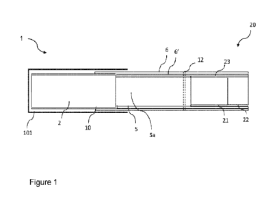
Figure 1 illustrates an article 1 for use as or as part of a non-combustible
aerosol
provision system. The article 1 may be a non-combustible aerosol provision
system
itself, or alternatively, may be for use with a non-combustible aerosol
provision device
to form a non-combustible aerosol provision system. One suitable non-
combustible
aerosol provision device 100 comprising a heater 101 is illustrated in figures
5 to 8B. In
other examples, other non-combustible aerosol provision devices may be used.
The article 1 comprises: a rod of aerosol generating material 2 comprising at
least one
aerosol forming material; and a mouth end section 20 disposed downstream of
the
aerosol generating material 2. The mouth end section 20 comprises a hollow
tubular
member 5. A first cylindrical body 21 is disposed downstream of the hollow
tubular
member 5. A second cylindrical body 22 is disposed adjacent to and downstream
of the
first cylindrical body 21.
In the present example, the article 1 includes a first body of material 21.
The first body
of material 21 is substantially cylindrical, and positioned downstream of the
hollow
tubular member 5. In the present example, the first body of material 21 is
directly
adjacent to the hollow tubular member 5.
The article 1 further includes a second body of material 22 adjacent to and
downstream
of the first body of material 21. In the present example, the second body of
material 22
CA 03214944 2023- 10-6
WO 2022/219318
PCT/GB2022/050909
- 13 -
is disposed at the mouth end of the article 1 such that the downstream end of
the
second body of material 22 forms the downstream end of the article 1.
Preferably, the length of the first body of material 21 is less than about 15
mm. More
preferably, the length of the first body of material 21 is less than about 12
mm. In
addition, or as an alternative, the length of the first body of material 21 is
at least about
5 mm. Preferably, the length of the first body of material 21 is at least
about 6 mm. In
some preferred embodiments, the length of the first body of material 21 is
from about 5
mm to about 15 mm, more preferably from about 7 mm to about 13 mm, even more
_to preferably from about 9 mm to about 11 mm, most preferably about 9 mm,
10 mm,
iimm, or 12MM. In the present example, the length of the first body of
material 21 is 10
mm. In other examples, the second body of material 22 has a length as
described above
in relation to the first body of material 21.
Preferably, the length of the second body of material 22 is less than about
iomm. More
preferably, the length of the second body of material is less than about 9mm,
less than
about 8mm, or less than about 7mm. In addition, or as an alternative, the
length of the
second body of material is at least about 3mm. Preferably, the length of the
first body is
at least about 4mm, more preferably at least about 5mm, most preferably about
5mm,
6mm, or 7mm. In some preferred embodiments, the length of the second body of
materia122is between 3 and 9mm, between mm and 7mm, most preferably about
5mm, 6mm, or 7mm. In the present example, the length of the second body of
material
22 is 6mm. In other examples, the first body of material 21 has a length as
described
above in relation to the second body of material 22.
Preferably, the first body of material 21 is longer than the second body of
material 22.
However, in some examples, the length of the first body of material 21 and the
second
body of material 22 are the same. In other examples, the length of the first
body of
material 21 is shorter than the length of the second body of material 22.
Preferably, the combined length of the first body of material 21 and the
second body of
material 22 is at least iomm, more preferably at least 12MM, and still more
preferably
at least 14mm. Preferably, the combined length of the first body of material
21 and the
second body of material 22 is less than about 20MM, more preferably less than
about
18mm. In some preferred embodiments, the combined length of the first body of
material 21 and the second body of material 22 is between 12 and 20MM, more
CA 03214944 2023- 10-6
WO 2022/219318
PCT/GB2022/050909
- 14 -
preferably between 14 and 18mm. In the present example, the combined length of
the
first body of material 21 and the second body of material 22 is about 16mm.
An article according to any of claims 1 to 19, wherein the combined length of
the first
and second cylindrical bodies is between 10 and 20MM, between 12 and 18mm,
between 14 and 17mm, or approximately 16mm.
By providing second body of material 22 in addition to the first body of
material 21,
having lengths within the ranges described above, the percentage reduction of
toxicant
io levels from the article emissions can be increased, compared to a single
body of
material 21. That is, a greater reduction in toxicants can be achieved through
provision
of a second body of material 22 in addition to the first body of material 21.
It has also been found that, by providing second body of material 22 in
addition to the
first body of material 21, the length of hollow tubular member 5 can be
reduced while
achieving desirable percentage reductions in toxicant levels of the article
emissions.
In the present example, the first body of material 21 and second body of
material 22 are
each formed from filamentary tow. In the present example, the tow used in the
first
body of material 21 and the second body of material 22 are the same. However,
in
other embodiments, the tow used for the first body of material 21 may be
different to
the tow used for the second body of material 22.
In the present example, the tow used in the body of material 21 and body of
material 22
each have a denier per filament (d.p.f.) of 8.4 and a total denier of 21,000.
Alternatively, the tow can, for instance, have a denier per filament (d.p.f.)
of 9.5 and a
total denier of 12,000. Alternatively, the tow can, for instance, have a
denier per
filament (d.p.f.) of 8 and a total denier of 15,000. In the present example,
the tow
comprises plasticised cellulose acetate tow. The plasticiser used in the tow
comprises
about 7% by weight of the tow. In the present example, the plasticiser is
triacetin.
In other examples, different materials can be used to form the first body of
material 21
and/or the second body of material 22. For instance, rather than tow, the
first body of
material 21 and/or the second body of material 22 can be formed from paper,
for
instance in a similar way to paper filters known for use in cigarettes.
Alternatively, the
first body 21 and/or second body 22 can be formed from tows other than
cellulose
CA 03214944 2023- 10-6
WO 2022/219318
PCT/GB2022/050909
- 15 -
acetate, for instance polylactic acid (PLA), other materials described herein
for
filamentary tow or similar materials, such as paper filter material.
The tow is preferably formed from cellulose acetate. The tow, whether formed
from
cellulose acetate or other materials, preferably has a d.p.f. of at least 5,
more preferably
at least 6 and still more preferably at least 7. These values of denier per
filament
provide a tow which has relatively coarse, thick fibres with a lower surface
area which
result in a lower pressure drop across the first body of material 21 and/or
second body
of material 22 than tows having lower d.p.f. values. Preferably, to achieve a
sufficiently
uniform first body of material 21 and/or second body of material 22, the tow
has a
denier per filament of no more than 12 d.p.f., preferably no more than n
d.p.f. and still
more preferably no more than 10 d.p.f.
In the present example, the first body of material 21 has the same denier per
filament
value as the second body of material 22. However, in other examples, the first
body of
material 21 may have a different denier per filament value to the second body
of
material 22.
The total denier of the tow forming the first body of material 21 and/or
second body of
material 22 is preferably at most 30,000, more preferably at most 28,000 and
still
more preferably at most 25,000. These values of total denier provide a tow
which takes
up a reduced proportion of the cross sectional area of the article 1 which
results in a
lower pressure drop across the article 1 than tows having higher total denier
values.
For appropriate firmness of the body of material 21 and/or second body of
material 22,
the tow preferably has a total denier of at least 8,000 and more preferably at
least
10,000.
In the present example, the first body of material 21 has the same total
denier value as
the second body of material 22. However, in other examples, the first body of
material
21 may have a different total denier value to the second body of material 22.
For
example, the first body of material 21 may have a lower total denier value
than the
second body of material 22. This may result in the second body of material 22
being
more firm than the first body of material. The first body of material 21 may
have a
lower total denier than the second body of material 21 providing for improved
cooling.
Therefore, the aerosol may retain desirable cooling characteristics while the
article
retains its shape at the mouth end of the article.
CA 03214944 2023- 10-6
WO 2022/219318
PCT/GB2022/050909
- 16 -
In another example, the first body of material 21 may have a higher total
denier value
than the second body of material 22. This may result in the first body of
material 21
being more firm than the first body of material. Having a high level of
firmness of the
first body of material may provide for greater rigidity and support of the
article 1. .
The, the second body of material 22 may be provided with a lower total denier
than the
first body of material 21 and may provide for improved cooling of the aerosol
passing
through the second body of material 22. Therefore, the rigidity of the article
1 can be
improved while retaining desirable cooling characteristics of the aerosol.
Preferably, the denier per filament of each of first body of material 21 and
second body
of material 22 is between 5 and 12 while the total denier is between 10,000
and 25,000.
More preferably, the denier per filament is between 6 and 10 while the total
denier is
between 11,000 and 22,000. Preferably the cross-sectional shape of the
filaments of
tow are 'Y' shaped, although in other embodiments other shapes such as 'X'
shaped or
'0' shaped filaments can be used, with the same d.p.f. and total denier values
as
provided herein. The tow may comprise filaments having a cross-section with an
isoperimetric ratio of 25 or less, preferably 20 or less, and more preferably
15 or less.
In some examples, the first body of material 21 and/or second body of material
22 may
comprise an adsorbent material (e.g. charcoal) dispersed within the tow.
Irrespective of the material used to form the first body 21 and/or second body
22, the
pressure drop across first body 21 and/or second body 22, can, for instance,
be between
0.2 and 5mmWG per mm of length of the first body 21 and/or second body 22, for
instance between 0.5mmWG and 3mmWG per mm of length of the body 21, 22. The
pressure drop can, for instance, be between 0.5 and 2.5mmWG/mm of length,
between
1 and 1.5mmWG/mm of length or between 1.5 and 2.5mmWG/mm of length. The total
pressure drop across first body 21 and/or second body 22 can, for instance, be
between
2mmWG and 8mWG, or between 4mmWG and 7mmWG. The total pressure drop
across body 21 and/or second body 22 can be about 5, 6 or 7mmWG.
The first body of material 21 and/or second body of material 22, also referred
to as
cylindrical body 21 and cylindrical body 22 respectively, can be formed
without any
cavities or hollow portions, for instance without cavities or hollow portions
having a
dimension greater than 0.5mm therein. For instance, the cylindrical body of
material
21 and/or cylindrical body of material 22 can comprise material which extends
CA 03214944 2023- 10-6
WO 2022/219318
PCT/GB2022/050909
- 17 -
substantially continuously throughout its volume. They can, for instance, have
a
density which is substantially uniform across its diameter and/or along its
length.
The first body of material 21 is wrapped in an additional wrapping material,
such as a
first plug wrap 23. In the present example, the second body of material 22 is
also
wrapped with the first plug wrap 23, such that the first plug wrap 23 joins
the first body
of material 21 to the second body of material 22. Alternatively, in other
examples, the
first body of material 21 and the second body of material 22 may be
individually
wrapped in a plug wrap 23. In case the first body of material 21 and the
second body of
io material 22 are wrapped individually, the first and second bodies of
material 21, 22 may
be combined by wrapper 6 and/or wrapper 6'.
In some examples, the first plug wrap 23 has a basis weight of less than 50
gsm, for
instance between about 20 gsm and 40 gsm. For instance, the first plug wrap 23
can
have a thickness of between 30 um and 6o um, or between 35 pm and 45 um.
In other examples, the first plug wrap 23 has a basis weight greater than 65
gsm, for
instance greater than 80 gsm, or greater than 95 gsm. In some examples, the
first plug
wrap 23 has a basis weight of about wo gsm.
In some examples, the first plug wrap 23 is provided with an embossed pattern.
The
embossed pattern may be provided on the plug wrap in a region surrounding the
first
cylindrical body 21 and/or the second cylindrical body 22. It has
advantageously been
found that providing a first plug wrap having a basis weight in the ranges
specified
above and comprising an embossed pattern can reduce the temperature of the
external
surface of the article 1 at a position overlying the first cylindrical body 21
and/or the
second cylindrical body 22. For instance, first plug wrap 23 may be provided
with an
embossed pattern comprising a hexagonal repeating pattern, a linear repeating
pattern,
or a series of raised areas having any suitable shape. Without wishing to be
bound by
theory, it is thought that providing an embossed first plug wrap 23 can
provide an air
gap between the plug wrap and the additional wrapper 10, which can reduce heat
transfer to the external surface of the article 1.
Preferably, the first plug wrap 23 is a non-porous plug wrap, for instance
having a
permeability of less than loo Coresta units, for instance less than 50 Coresta
units.
CA 03214944 2023- 10-6
WO 2022/219318
PCT/GB2022/050909
- 18 -
However, in other embodiments, the first plug wrap 23 can be a porous plug
wrap, for
instance having a permeability of greater than 200 Coresta units.
The hollow tubular member 5 is provided between the aerosol generating
material 2
and the cylindrical body 21. The hollow tubular member 5 may also be referred
to
herein as a cooling section. The length of the hollow tubular member 5 may be
such
that the cylindrical body 21 is spaced away from the aerosol generating
material 2 by a
maximum distance d. In the present example, the hollow tubular member 5 has a
length of 21 mm. The cylindrical body 21 is therefore separated from the
aerosol
io generating material by a distance d of 21 mm. Preferably, the maximum
distance
between the cylindrical body 21 and the aerosol generating material 2 is 22
mm.
Suitably, the distance d may be 21 MM. It has been surprisingly found that by
providing
a cooling section configured to extend a maximum of 22 mm from the aerosol
generating material, an improved aerosol may be provided. It is hypothesised
that
limiting the combined length of the cooling sections to less than 22 mm may
reduce the
condensation of desirable components of the aerosol on the inner surfaces of
the
cooling section.
Preferably, the hollow tubular member 5 has a wall thickness of at least 300
microns
and/or a permeability of at least wo Coresta units. By constructing the hollow
tubular
member 5 to have a permeability of at least loo Coresta units, the hollow
tubular
member takes up moisture from aerosol generated by the aerosol generating
material 2
when the article 1 is heated by the non-combustible aerosol provision device
loo.
Futhermore, papers with permeability greater than wo Coresta units are
generally low
weight and easier to work with during manufacturing.
In the present example the hollow tubular member 5 is formed from paper.
Specifically,
the hollow tubular member 5 is formed from a plurality of layers of paper
which are
parallel wound, with butted seams, to form the tubular member 5, which
underlies a
wrapper 6. The paper tube provides additional rigidity to the first cavity 5a.
In the
present example, first and second paper layers are provided in a two-ply tube,
although
in other examples 3, 4 or more paper layers can be used forming 3, 4 or more
ply tubes.
Other constructions can be used, such as spirally wound layers of paper,
cardboard
tubes, tubes formed using a papier-mache type process, moulded or extruded
plastic
tubes or similar.
CA 03214944 2023- 10-6
WO 2022/219318
PCT/GB2022/050909
- 19 -
The hollow tubular member 5 can also be formed using a stiff plug wrap and/or
tipping
paper, for instance as the wrapper 6 and/or further wrapper 6' described in
more detail
below, meaning that a separate tubular element is not required. The stiff plug
wrap
and/or tipping paper is manufactured to have a rigidity that is sufficient to
withstand
the axial compressive forces and bending moments that might arise during
manufacture and whilst the article 1 is in use. For instance, the stiff plug
wrap and/or
tipping paper can have a basis weight between 70 gsm and 120 gsm, more
preferably
between 80 gsm and no gsm. Additionally or alternatively, the stiff plug wrap
and/or
tipping paper can have a thickness between 80 nm and 200 M, more preferably
io between 100 um and i6o um, or from 120 pin to 150 pin. It can be
desirable for both
the wrapper 6 and/or further wrapper 6' to have values in these ranges, to
achieve an
acceptable overall level of rigidity for the hollow tubular member 5.
In other examples, the hollow tubular member 5 may be formed from other
materials,
such as a moulded or extruded plastic tube, or a fibrous material, as
described in
relation to the tow of cylindrical bodies 21 and 22.
The hollow tubular member 5 preferably has a wall thickness, which can be
measured,
for example using a calliper, of at least about wo nm and up to about 1.5mm,
preferably between wo nrn and 1 mm and more preferably between 150 pm and 500
pm, or about 300 um. In the present example, the hollow tubular member 5 has a
wall
thickness of about 250 p.m.
Preferably, the length of the hollow tubular member 5 is less than about 26
mm. More
preferably, the length of the hollow tubular member 5 is less than about 22
mm.
Additionally or alternatively, the length of the hollow tubular member 5 is
preferably at
least about 5 mm. Preferably, the length of the hollow tubular member 5 is at
least
about lo mm. In some preferred embodiments, the length of the hollow tubular
member 5 is from about 18 mm to about 24 mm, more preferably from about 20
ifirri to
about 22 MIT1, most preferably about 21 mm. In the present example, the length
of the
hollow tubular member 5 is 21 mm.
The hollow tubular member 5 is located around and defines an air gap within
the
mouthpiece 20 which act as a cooling segment. The air gap provides a chamber
through
which heated volatilised components generated by the aerosol generating
material 2
flow.
CA 03214944 2023- 10-6
WO 2022/219318
PCT/GB2022/050909
- 20 -
The cavity 5a can, for instance, have an internal volume greater than 100 mm3,
for
instance greater than 200 mm3, 300MM3, 350 M3, 400 mm3, or 500 mm3, allowing
further improvement of the aerosol. In some examples, the cavity 5a comprises
a
volume of between about 400 mm3 and about 600 mm3, or between about 450 mm3
and about 550 mm3, for instance about 500 mm3.
Preferably, the cavity 5a has an internal volume greater than about 400 mm3.
Providing cavities of at least these volumes has been found to enable the
formation of
_ro an improved aerosol, as well as providing the cooling function
described herein. Such
cavity size provides sufficient space within the mouthpiece 20 to allow heated
volatilised components to cool, therefore allowing the exposure of the aerosol
generating material 2 to higher temperatures than would otherwise be possible,
since
they may result in an aerosol which is too warm.
The hollow tubular member 5 can be configured to provide a temperature
differential of
at least 40 degrees Celsius between a heated volatilised component entering a
first,
upstream end of the hollow tubular member 5 and a heated volatilised component
exiting a second, downstream end of the hollow tubular member 5. The hollow
tubular
member 5 is preferably configured to provide a temperature differential of at
least 6o
degrees Celsius, preferably at least 8o degrees Celsius and more preferably at
least loo
degrees Celsius between a heated volatilised component entering a first,
upstream end
of the hollow tubular member 5 and a heated volatilised component exiting a
second,
downstream end of the hollow tubular member 5. This temperature differential
across
the length of the hollow tubular member 5 protects the first and second bodies
of
material 21, 22 from the high temperatures of the aerosol generating material
3 when
they are heated.
In each embodiment, the article further comprises the wrapper 6 at least
partially
surrounding the aerosol generating material 2 and the hollow tubular member 5
to
connect the aerosol generating material 2 to the hollow tubular member 5. In
some
examples the wrapper may extend along the full length of the article 1 to
attach the
aerosol generating material 2 to the components of the mouth end section 20.
In the
present example, a further wrapper 6' underlies the wrapper 6, and extends
along the
mouth end section 20. Further wrapper 6' combines the hollow tubular member 5,
first
cylindrical body 21, and second cylindrical body 22. In the present example,
wrapper 6
CA 03214944 2023- 10-6
WO 2022/219318
PCT/GB2022/050909
- 21 -
extends partially along the length of the aerosol generating material 2 to
attach the
aerosol generating material to the wrapped mouth end section 20.
A plug wrap 23 circumscribes the cylindrical body 21. Further wrapper 6'
circumscribes
and attaches the second cylindrical body 22 to the first cylindrical body of
material 21,
and the hollow tubular member 5. The wrapped second cylindrical body 22, first
cylindrical body 21, and hollow tubular member 5 are attached to the aerosol
generating material 2 by wrapper 6.
_to The wrapper 6 may be a paper material comprising a citrate, such as
sodium nitrate or
potassium nitrate. In such examples, the wrapper 6 may have a citrate content
of 2% by
weight or less, or 1% by weight or less. This reduces charring of the wrapper
6 when the
article 1 is heated in the non-combustible aerosol provision device too.
In some embodiments, the aerosol generating material 2 described herein is a
first
aerosol generating material 2 and the hollow tubular body 3 may comprise a
second
aerosol generating material. For example, the second aerosol generating
material may
be disposed on an inner surface of the hollow tubular member 5.
The second aerosol generating material comprises at least one aerosol former
material,
and may also comprise at least one aerosol modifying agent, or other sensate
material.
The aerosol former material and/or aerosol modifying agent can be any aerosol
former
material or aerosol modifying agent as described herein, or a combination
thereof.
In use, as the aerosol generated from the first aerosol generating material 2
is drawn
through the hollow tubular member 5, heat from the first aerosol may
aerosolise the
aerosol forming material of the second aerosol generating material, to form a
second
aerosol. The second aerosol may comprise a flavourant, which may be additional
or
complementary to the flavour of the first aerosol.
Providing a second aerosol generating material on the hollow tubular member 5
can
result in generation of a second aerosol which boosts or complements the
flavour or
visual appearance of the first aerosol.
The article 1 may further comprise at least one ventilation area 12 arranged
to allow
external air to flow into the article. In the illustrated embodiments, the
ventilation area
CA 03214944 2023- 10-6
WO 2022/219318
PCT/GB2022/050909
- 22 -
12 comprises a row of ventilation apertures, or perforations, cut into the
wrapper 6. The
ventilation apertures may extend in a line around the circumference of the
article 1. The
ventilation area 12 may comprise two or more rows of ventilation apertures. By
providing a ventilation area 12, ambient air may be drawn into the article
during use to
further cool the aerosol.
In the illustrated embodiments, the at least one ventilation area 12 is
arranged to
provide external air into the cavity 5a of the hollow tubular member 5. To
achieve this,
the one or more rows of ventilation apertures extend around the circumference
of the
rrr article over the hollow tubular member 5.
Suitably, the ventilation area 12 may be provided at a position between 14 mm
and 20
mm downstream of the aerosol generating material 2. For instance, the
ventilation area
may be provided at a position about 14.5 mm or 18.5 mm downstream of the
aerosol
generating material 2. In other examples, ventilation may be provided at a
position 22.5
mm upstream of the mouth end of the article.
In one example, the ventilation area 12 comprises a single row of perforations
formed
as laser perforations. In some other examples, the ventilation area comprises
first and
second parallel rows of perforations formed as laser perforations, for
instance at
positions 17.925 mm and 18.625 mm respectively from the mouth end. These
perforations pass though the wrapper 6 and hollow tubular member 5. In
alternative
embodiments, the ventilation can be provided at other locations.
It has been surprisingly found that by locating the ventilation area 12 closer
to the
mouth end of the article, and particularly at approximately 18.5mm, the
reduction in
certain toxicants from the generated aerosol passing through the article and
exiting the
mouth end is greater than the reduction in those toxicants when a ventilation
area is
provided closer to the aerosol generating material.
However, it has also been found that providing ventilation closer to the mouth
end
results in higher nicotine delivery compared to articles having ventilation
provided
closer to the aerosol generating material.
Without wishing to be bound by theory, it is also believed that providing
ventilation
closer to the mouth end also results in higher delivery of aerosol forming
agent (e.g.
CA 03214944 2023- 10-6
WO 2022/219318
PCT/GB2022/050909
- 23 -
glycerol) to the user, compared to articles having ventilation provided closer
to the
aerosol generating material.
Therefore, an article 1 as illustrated in Figure 1 can provide higher
deliveries of nicotine
and aerosol while reducing the levels of undesirable toxicants by providing a
ventilation
area closer to the mouth end of the article.
In some examples, the perforations pass through the full thickness of the wall
of the
hollow tubular member 5. In other examples, the ventilations may be formed
through
io only a portion of the wall thickness of the tubular member 5. For
example, the
ventilation perforation may extend into the tubular member by a depth of up to
about
0.2 mm, or up to about 0.3 mm, or up to about 0.4 mm.
Alternatively, the ventilation can be provided via a single row of
perforations, for
instance laser perforations, into the portion of the article 1 in which the
hollow tubular
member 5 is located. This has been found to result in improved aerosol
formation,
which is thought to result from the airflow through the perforations being
more
uniform than with multiple rows of perforations, for a given ventilation
level. In the
present example, the ventilation area 12 comprises a single row of laser
perforations
18.5 mm downstream of the aerosol generating material 2.
It shall be appreciated that the exact location of the at least one
ventilation area 12 is
not essential. In another embodiment, the at least one ventilation area 12 is
arranged to
provide external air into the aerosol generating material 2. To achieve this,
the one or
more rows of ventilation apertures extend around the circumference of the
article over
the rod of aerosol generating material 2.
The level of ventilation provided by the at least one ventilation area 12 is
within the
range of 40% to 70% of the volume of aerosol generated by the aerosol
generating
material 2 passing through the article 1, when the article 1 is heated in the
non-
combustible aerosol provision device loo.
Aerosol temperature has been found to generally increase with a drop in the
ventilation
level. However the relationship between aerosol temperature and ventilation
level does
not appear to be linear, with variations in ventilation, for instance due to
manufacturing tolerances, having less impact at lower target ventilation
levels. For
CA 03214944 2023- 10-6
WO 2022/219318
PCT/GB2022/050909
- 24 -
instance, with a ventilation tolerance of 15%, for a target ventilation level
of 75%, the
aerosol temperature could increase by approximately 6 C at the lower
ventilation limit
(60% ventilation). However, with a target ventilation level of 6o% the aerosol
temperature may only increase by approximately 3.5 C at the lower vent limit
(45%
ventilation). The target ventilation level of the article can therefore be
within the range
40% to 70%, for instance, 45% to 65%. The mean ventilation level of at least
20 articles
can be between 40% and 70%, for instance between 45% and 70% or between 51%
and
59%.
In some embodiments, an additional wrapper 10 at least partially surrounds the
aerosol
generating material 2, between the aerosol generating material 2 and the
wrapper 6. In
particular, during manufacture of the article, the aerosol generating material
is first
wrapped by additional wrapper 10 before being attached in combination with the
other
components of the article 1 by wrapper 6.
In some embodiments, the additional wrapper 10 surrounding the aerosol
generating
material has a high level of permeability, for example greater than about woo
Coresta
Units, or greater than about 1500 Coresta Units, or greater than about 2000
Coresta
Units. The permeability of the additional wrapper 10 can be measured in
accordance
with ISO 2965:2009 concerning the determination of air permeability for
materials
used as cigarette papers, filter plug wrap and filter joining paper.
The additional wrapper 10 may be formed from a material with a high inherent
level of
permeability, an inherently porous material, or may be formed from a material
with
any level of inherent permeability where the final level of permeability is
achieved by
providing the additional wrapper 10 with a permeable zone or area. Providing a
permeable additional wrapper lo provides a route for air to enter the smoking
article.
The additional wrapper lo can be provided with a permeability such that the
amount of
air entering through the rod of aerosol generating material 2 is relatively
more than the
amount of air entering the article 1 through the ventilation area 12 in the
mouthpiece.
An article 1 having this arrangement may produce a more flavoursome aerosol
which
may be more satisfactory to the user.
Figure 2 illustrates an article 1' for use as or as part of a non-combustible
aerosol
provision system. Article 1' is the same as article 1, except that cylindrical
body 21 of the
mouth end section 20' comprises a capsule 24. The capsule 24 can comprise a
CA 03214944 2023- 10-6
WO 2022/219318
PCT/GB2022/050909
- 25 -
breakable capsule, for instance a capsule which has a solid, frangible shell
surrounding
a liquid payload. In the present example, a single capsule is used. The
capsule is
entirely embedded within the body of material 21'. In other words, the capsule
is
completely surrounded by the material forming the body. In other examples, a
plurality of breakable capsules may be disposed within the body of material
21', for
instance 2, 3 or more breakable capsules. The length of the body of material
21' can be
increased to accommodate the number of capsules required. In examples where a
plurality of capsules is used, the individual capsules may be the same as each
other, or
may differ from one another in terms of size and/or capsule payload. In other
examples, a capsule may be provided within second body of material 22 in
addition/alternatively to the first body of material 21'. In other examples,
more than
two bodies of material may be provided, with each body containing one or more
capsules.
The capsule 24 has a core-shell structure. In other words, the capsule 24
comprises a
shell encapsulating a liquid agent, for instance a flavourant or other agent,
which can be
any one of the flavourants or aerosol modifying agents described herein. The
shell of
the capsule 24 can be ruptured by a user to release the flavourant or other
agent into
the body of material 21. The first plug wrap 23 can comprise a barrier coating
to make
the material of the plug wrap substantially impermeable to the liquid payload
of the
capsule. Alternatively or in addition, the further wrapper 6' and/or wrapping
material
6 can comprise a barrier coating to make the material of that further wrapper
6' and/or
wrapping material 6 substantially impermeable to the liquid payload of the
capsule.
In some examples, the capsule is spherical and has a diameter of about 3 mm.
In other
examples, other shapes and sizes of capsule can be used. The total weight of
the
capsule may be in the range about 10 mg to about 50 mg.
It is known to generate, for a given tow specification (such as 8.4Y21000), a
tow
capability curve which represents the pressure drop through a length of rod
formed
using the tow, for each of a range of tow weights. Parameters such as the rod
length
and circumference, wrapper thickness and tow plasticiser level are specified,
and these
are combined with the tow specification to generate the tow capability curve,
which
gives an indication of the pressure drop which would be provided by different
tow
weights between the minimum and maximum weights achievable using standard
filter
rod forming machinery. Such tow capability curves can be calculated, for
instance,
CA 03214944 2023- 10-6
WO 2022/219318
PCT/GB2022/050909
- 26 -
using software available from tow suppliers. It has been found that it is
particularly
advantageous to use a body of material 21' which includes filamentary tow
having a
weight per mm of length of the body of material 21' which is between about 10%
and
about 30% of the range between the minimum and maximum weights of a tow
capability curve generated for the filamentary tow. This can provide an
acceptable
balance between providing enough tow weight to avoid shrinkage after the body
21' has
been formed, providing an acceptable pressure drop, while also assisting with
capsule
placement within the tow, for capsules of the sizes described herein.
io The body of material 21' and body of material 22' may have different
denier per
filament values and/or total denier values to each other in order to achieve
desirable
pressure drop and firmness characteristics when the capsule 24 is included in
the body
of material 21'
A method of manufacturing an article for use with a non-combustible aerosol
provision
device loo comprising a heater 101 will now be described with reference to
Figure 3.
The method comprises:
the step Si of providing an aerosol generating material 2 comprising at least
one
aerosol forming material;
the step S2 of disposing a cylindrical body 21 downstream of the aerosol
generating material, such that the upstream end of the cylindrical body 21 is
less than
about 22 mm from the downstream end of the aerosol generating material 2;
the step S3 of disposing a first cylindrical body downstream of the tubular
member 5;
the step S4 of disposing a second cylindrical body adjacent to and downstream
of the first cylindrical body.
Figure 4 illustrates an article 1" for use as or as part of a non-combustible
aerosol
provision system. Article 1" is the same as article 1, except a tubular body 3
is further
provided between the tubular member 5 and the first cylindrical body 21.
Additionally/alternatively, a second tubular body 24 may be provided at the
mouth end
of the article.
The hollow tubular body 3 is configured to serve as a heat dissipater to
reduce the
phenomena of 'hot puff. 'Hot puff is defined as aerosol delivered to the user
at an
uncomfortably high temperature. Hot puff may be exacerbated when a user draws
CA 03214944 2023- 10-6
WO 2022/219318
PCT/GB2022/050909
- 27 -
aerosol through a heated article 1 at a high rate, reducing the time for heat
in the
aerosol to be dissipated. When inserted into a non-combustible aerosol
provision
device mo, the hollow tubular body 3 separates the mouth end section from the
heater
101 to provide space for heat to dissipate before the aerosol reaches the
downstream
end of the article. Further, it shall be appreciated that heat will be
conducted away from
the aerosol and into the hollow tubular body 3 as the aerosol is drawn
therethrough. In
this way, the hollow tubular body 3 acts as a heat sink.
In the present example, hollow tubular body 3 is formed from filamentary tow.
In other
embodiments, other constructions may be used, such as spirally wound layers of
paper,
cardboard tubes, tubes formed using a papier-mâché type process, tubes formed
from
paper filter material, moulded or extruded plastic tubes or similar.
The hollow tubular body 3 preferably has a wall thickness of at least about
325 um and
up to about 2 mm, preferably between 500 pm and 2 mm and more preferably
between
mo um and 1.5 mm. In the present example, the hollow tubular body 3 has a wall
thickness of about 1.4 mm. The "wall thickness" of the hollow tubular body 3
corresponds to the thickness of the wall of the hollow tubular body 3 in a
radial
direction. This may be measured, for example, using a caliper. The use of
filamentary
tow and/or wall thicknesses in these ranges have advantage of insulating the
hot
aerosol passing through the second cavity 3a from the outer surface of the
hollow
tubular body 3.
The wall thickness together with the external diameter of the hollow tubular
body 3
together define the internal diameter or cavity size of the hollow tubular
body 3.
In some embodiments, the thickness of the wall of the hollow tubular body 3 is
at least
325 microns and, preferably, at least 400, 500, 60o, 700, 8o0, 900 or woo
microns. In
some embodiments, the thickness of the wall of the hollow tubular body 3 is at
least
1250 or 1500 microns.
In some embodiments, the thickness of the wall of the hollow tubular body 3 is
less
than 2000 microns and, for instance, less than 1500 microns.
The increased thickness of the wall of the hollow tubular body 3 means that it
has a
greater thermal mass, which has been found to help reduce the temperature of
the
CA 03214944 2023- 10-6
WO 2022/219318
PCT/GB2022/050909
- 28 -
aerosol passing through the hollow tubular body 3 and reduce the surface
temperature
of the mouth end section 20 at locations downstream of the hollow tubular body
3. This
is thought to be because the greater thermal mass of the hollow tubular body 3
allows
the hollow tubular body 3 to absorb more heat from the aerosol in comparison
to a
hollow tubular body 3 with a thinner wall thickness. The increased thickness
of the
hollow tubular body 3 also channels the aerosol centrally through the mouth
end
section 20 such that less heat from the aerosol is transferred to the outer
portions of the
mouth end section 20.
/0 Preferably, the density of the hollow tubular body 3 is at least about
0.25 grams per
cubic centimetre (g/cc), more preferably at least about 0.3 g/cc. Preferably,
the density
of the hollow tubular body 3 is less than about 0.75 grams per cubic
centimetre (g/cc),
more preferably less than 0.6 g/cc. In some embodiments, the density of the
hollow
tubular body 3 is between 0.25 and 0.75 g/cc, more preferably between 0.3 and
0.6
g/cc, and more preferably between 0.4 g/cc and o.6 g/cc or about 0.5 g/cc.
These
densities have been found to provide a good balance between improved firmness
afforded by denser material and the lower heat transfer properties of lower
density
material. For the purposes of the present example, the "density" of the hollow
tubular
body 3 refers to the density of the filamentary tow forming the element with
any
plasticiser incorporated. For the purposes of the present invention, the
"density" of the
material forming the hollow tubular body 3 refers to the density of any
filamentary tow
forming the element with any plasticiser incorporated. The density may be
determined
by dividing the total weight of the material forming the hollow tubular body 3
by the
total volume of the material forming the hollow tubular body 3, wherein the
total
volume can be calculated using appropriate measurements of the material
forming the
hollow tubular body 3 taken, for example, using callipers. Where necessary,
the
appropriate dimensions may be measured using a microscope.
The filamentary tow forming the hollow tubular body 3 preferably has a total
denier of
less than 45,000, more preferably less than 42,000. This total denier has been
found to
allow the formation of a tubular element 13 which is not too dense.
Preferably, the total
denier is at least 20,000, more preferably at least 25,000. In preferred
embodiments,
the filamentary tow forming the hollow tubular body 3 has a total denier
between
25,000 and 45,000, more preferably between 35,000 and 45,000. Preferably the
cross-sectional shape of the filaments of tow are 'Y' shaped, although in
other
embodiments other shapes such as 'X' shaped filaments can be used.
CA 03214944 2023- 10-6
WO 2022/219318
PCT/GB2022/050909
- 29 -
The filamentary tow forming the hollow tubular body 3 preferably has a denier
per
filament of greater than 3. This denier per filament has been found to allow
the
formation of a tubular element 13 which is not too dense. Preferably, the
denier per
filament is at least 4, more preferably at least 5. In preferred embodiments,
the
filamentary tow forming the hollow tubular body 3 has a denier per filament
between 4
and 10, more preferably between 4 and 9. In one example, the filamentary tow
forming
the hollow tubular body 3 has an 8Y4o,000 tow formed from cellulose acetate
and
comprising 18% plasticiser, for instance triacetin.
The hollow tubular body 3 preferably comprises from 10% to 22% by weight of
plasticiser. For cellulose acetate tow, the plasticiser is preferably
triacetin, although
other plasticisers such as polyethelyne glycol (PEG) can be used. The hollow
tubular
body 3 can comprise less than about 18% by weight of plasticiser, such as
triacetin, or
less than about 17%, less than about 16% or less than about 15%. More
preferably, the
tubular body 3 comprises from lo% to 20% by weight of plasticiser, for
instance about
11%, about 12%, about 13%, about 15%, about 17%, about 18% or about 19%
plasticiser.
In some embodiments, the permeability of the material of the wall of the
hollow tubular
body 3 is at least wo Coresta Units and, preferably, at least 500 or woo
Coresta Units.
It has been found that the relatively high permeability of the hollow tubular
body 3
increases the amount of heat that is transferred to the hollow tubular body 3
from the
aerosol and thus reduces the temperature of the aerosol. The permeability of
the hollow
tubular body 3 has also been found to increase the amount of moisture that is
transferred from the aerosol to the hollow tubular body 3, which has been
found to
improve the feel of the aerosol in the user's mouth. A high permeability of
hollow
tubular body 3 also makes it easier to cut ventilation holes into the hollow
tubular body
3 using a laser, meaning that a lower power of laser can be used.
The hollow tubular body 3 may comprise a filamentary tow comprising filaments
having a cross-section with an isoperimetric ratio L2/A of 25 or less, 20 or
less or 15 or
less, where L is the length of the perimeter of the cross section and A is the
area of the
cross section. In other words, the filaments may comprise a substantially `c.'
shaped
cross section, or at least as close as it is possible to achieve. For a given
denier per
filament, filaments with a substantially '0' shaped cross section have a lower
surface
CA 03214944 2023- 10-6
WO 2022/219318
PCT/GB2022/050909
-30 -
area than other cross sectional shapes, such as 'Y' or 'X' shaped filaments.
Therefore,
the delivery of aerosol to the user is improved.
It shall be appreciated that aerosol drawn through the hollow tubular body 3
passes
through both a central second cavity 3a in the hollow tubular body 3 and also
partly
through the filaments of the hollow tubular body 3 itself. By providing
filaments with a
substantially 'o' shaped cross section, a greater proportion of aerosol will
pass through
the filament of the hollow tubular body 3 itself, increasing heat transfer to
the hollow
tubular body 3 yet further.
In the present example, hollow tubular body 3 has a length of 9 mm. In other
examples,
hollow tubular body may have a length up to about 12 mm, for instance io mm.
The hollow tubular body 3 and hollow tubular member 5 may also be referred to
as
cooling sections, and define respective first and second cavities 5a, 3a.
An example as described herein with reference to Figure 4 may also be provided
with a
capsule in one or both of the first and second cylindrical bodies 21, 22.
Figure 5 shows an example of a non-combustible aerosol provision device 100
comprising a heater 101 for generating aerosol from an aerosol generating
medium/material such as the aerosol generating material 2 of any of the
articles 1, 1', 1"
described herein. In the examples described herein, a generic article no
illustrated in
Figures 5 to 9 can be considered to correspond to any of the articles 1, 1',
1" described
herein. In broad outline, the device 100 may be used to heat a replaceable
article
comprising the aerosol generating medium, for instance the article 10
described herein,
to generate an aerosol or other inhalable medium which is inhaled by a user of
the
device 100. The device 100 and replaceable article no together form a system.
The device 100 comprises a housing 102 (in the form of an outer cover) which
surrounds and houses various components of the device 100. The device 100 has
an
opening 104 in one end, through which the article 110 may be inserted for
heating by a
heater 101, hereinafter referred to as the heating assembly. In use, the
article 110 may
be fully or partially inserted into the heating assembly where it may be
heated by one or
more components of the heater assembly.
CA 03214944 2023- 10-6
WO 2022/219318
PCT/GB2022/050909
- 31 -
The device 100 of this example comprises a first end member 106 which
comprises a lid
108 which is moveable relative to the first end member 106 to close the
opening 104
when no article no is in place. In Figure 5, the lid 108 is shown in an open
configuration, however the lid 108 may move into a closed configuration. For
example,
a user may cause the lid 108 to slide in the direction of arrow "B".
The device 100 may also include a user-operable control element 112, such as a
button
or switch, which operates the device 100 when pressed. For example, a user may
turn
on the device 100 by operating the switch 112.
The device 100 may also comprise an electrical component, such as a
socket/port 114,
which can receive a cable to charge a battery of the device 100. For example,
the socket
114 may be a charging port, such as a USB charging port.
Figure 6 depicts the device 100 of Figure 5 with the outer cover 102 removed
and
without an article 110 present. The device 100 defines a longitudinal axis
134.
As shown in Figure 6, the first end member 106 is arranged at one end of the
device 100
and a second end member 116 is arranged at an opposite end of the device 100.
The first
and second end members 106, 116 together at least partially define end
surfaces of the
device 100. For example, the bottom surface of the second end member 116 at
least
partially defines a bottom surface of the device 100. Edges of the outer cover
102 may
also define a portion of the end surfaces. In this example, the lid 108 also
defines a
portion of a top surface of the device 100.
The end of the device closest to the opening 104 may be known as the proximal
end (or
mouth end) of the device 100 because, in use, it is closest to the mouth of
the user. In
use, a user inserts an article 110 into the opening 104, operates the user
control 112 to
begin heating the aerosol generating material and draws on the aerosol
generated in the
device. This causes the aerosol to flow through the device 100 along a flow
path towards
the proximal end of the device 100.
The other end of the device furthest away from the opening 104 may be known as
the
distal end of the device 100 because, in use, it is the end furthest away from
the mouth
of the user. As a user draws on the aerosol generated in the device, the
aerosol flows
away from the distal end of the device 100.
CA 03214944 2023- 10-6
WO 2022/219318
PCT/GB2022/050909
- 32 -
The device too further comprises a power source 118. The power source 118
maybe, for
example, a battery, such as a rechargeable battery or a non-rechargeable
battery.
Examples of suitable batteries include, for example, a lithium battery (such
as a
lithium-ion battery), a nickel battery (such as a nickel¨cadmium battery), and
an
alkaline battery. The battery is electrically coupled to the heating assembly
to supply
electrical power when required and under control of a controller (not shown)
to heat
the aerosol generating material. In this example, the battery is connected to
a central
support 120 which holds the battery 118 in place.
_to The device further comprises at least one electronics module 122. The
electronics
module 122 may comprise, for example, a printed circuit board (PCB). The PCB
122
may support at least one controller, such as a processor, and memory. The PCB
122
may also comprise one or more electrical tracks to electrically connect
together various
electronic components of the device too. For example, the battery terminals
may be
electrically connected to the PCB 122 so that power can be distributed
throughout the
device too. The socket 114 may also be electrically coupled to the battery via
the
electrical tracks.
In the example device too, the heating assembly is an inductive heating
assembly and
comprises various components to heat the aerosol generating material of the
article no
via an inductive heating process. Induction heating is a process of heating an
electrically conducting object (such as a susceptor) by electromagnetic
induction. An
induction heating assembly may comprise an inductive element, for example, one
or
more inductor coils, and a device for passing a varying electric current, such
as an
alternating electric current, through the inductive element. The varying
electric current
in the inductive element produces a varying magnetic field. The varying
magnetic field
penetrates a susceptor suitably positioned with respect to the inductive
element, and
generates eddy currents inside the susceptor. The susceptor has electrical
resistance to
the eddy currents, and hence the flow of the eddy currents against this
resistance
causes the susceptor to be heated by Joule heating. In cases where the
susceptor
comprises ferromagnetic material such as iron, nickel or cobalt, heat may also
be
generated by magnetic hysteresis losses in the susceptor, i.e. by the varying
orientation
of magnetic dipoles in the magnetic material as a result of their alignment
with the
varying magnetic field. In inductive heating, as compared to heating by
conduction for
example, heat is generated inside the susceptor, allowing for rapid heating.
Further,
CA 03214944 2023- 10-6
WO 2022/219318
PCT/GB2022/050909
- 33 -
there need not be any physical contact between the inductive heater and the
susceptor,
allowing for enhanced freedom in construction and application.
The induction heating assembly of the example device 100 comprises a susceptor
arrangement 132 (herein referred to as "a susceptor"), a first inductor coil
124 and a
second inductor coil 126. The first and second inductor coils 124, 126 are
made from an
electrically conducting material. In this example, the first and second
inductor coils
124, 126 are made from Litz wire/cable which is wound in a helical fashion to
provide
helical inductor coils 124, 126. Litz wire comprises a plurality of individual
wires which
_ro are individually insulated and are twisted together to form a single
wire. Litz wires are
designed to reduce the skin effect losses in a conductor. In the example
device loo, the
first and second inductor coils 124, 126 are made from copper Litz wire which
has a
rectangular cross section. In other examples the Litz wire can have other
shape cross
sections, such as circular.
The first inductor coil 124 is configured to generate a first varying magnetic
field for
heating a first section of the susceptor 132 and the second inductor coil 126
is
configured to generate a second varying magnetic field for heating a second
section of
the susceptor 132. In this example, the first inductor coil 124 is adjacent to
the second
inductor coil 126 in a direction along the longitudinal axis 134 of the device
100 (that is,
the first and second inductor coils 124, 126 to not overlap). The susceptor
arrangement
132 may comprise a single susceptor, or two or more separate susceptors. Ends
130 of
the first and second inductor coils 124, 126 can be connected to the PCB 122.
It will be appreciated that the first and second inductor coils 124, 126, in
some
examples, may have at least one characteristic different from each other. For
example,
the first inductor coil 124 may have at least one characteristic different
from the second
inductor coil 126. More specifically, in one example, the first inductor coil
124 may
have a different value of inductance than the second inductor coil 126. In
Figure 5, the
first and second inductor coils 124, 126 are of different lengths such that
the first
inductor coil 124 is wound over a smaller section of the susceptor 132 than
the second
inductor coil 126. Thus, the first inductor coil 124 may comprise a different
number of
turns than the second inductor coil 126 (assuming that the spacing between
individual
turns is substantially the same). In yet another example, the first inductor
coil 124 may
be made from a different material to the second inductor coil 126. In some
examples,
the first and second inductor coils 124, 126 may be substantially identical.
CA 03214944 2023- 10-6
WO 2022/219318
PCT/GB2022/050909
- 34 -
In this example, the first inductor coil 124 and the second inductor coil 126
are wound
in opposite directions. This can be useful when the inductor coils are active
at different
times. For example, initially, the first inductor coil 124 may be operating to
heat a first
section/poition of the aiticle 110, and at a later time, the second inductor
coil 126 may
be operating to heat a second section/portion of the article 110. Winding the
coils in
opposite directions helps reduce the current induced in the inactive coil when
used in
conjunction with a particular type of control circuit. In Figure 5, the first
inductor coil
124 is a right-hand helix and the second inductor coil 126 is a left-hand
helix. However,
ro in another embodiment, the inductor coils 124, 126 may be wound in the
same
direction, or the first inductor coil 124 may be a left-hand helix and the
second inductor
coil 126 may be a right-hand helix.
The susceptor 132 of this example is hollow and therefore defines a receptacle
within
which aerosol generating material is received. For example, the article 110
can be
inserted into the susceptor 132. In this example the susceptor 120 is tubular,
with a
circular cross section.
The susceptor 132 may be made from one or more materials. Preferably the
susceptor
132 comprises carbon steel having a coating of Nickel or Cobalt.
In some examples, the susceptor 132 may comprise at least two materials
capable of
being heated at two different frequencies for selective aerosolization of the
at least two
materials. For example, a first section of the susceptor 132 (which is heated
by the first
inductor coil 124) may comprise a first material, and a second section of the
susceptor
132 which is heated by the second inductor coil 126 may comprise a second,
different
material. In another example, the first section may comprise first and second
materials,
where the first and second materials can be heated differently based upon
operation of
the first inductor coil 124. The first and second materials may be adjacent
along an axis
defined by the susceptor 132, or may form different layers within the
susceptor 132.
Similarly, the second section may comprise third and fourth materials, where
the third
and fourth materials can be heated differently based upon operation of the
second
inductor coil 126. The third and fourth materials may be adjacent along an
axis defined
by the susceptor 132, or may form different layers within the susceptor 132.
Third
material may the same as the first material, and the fourth material may be
the same as
CA 03214944 2023- 10-6
WO 2022/219318
PCT/GB2022/050909
- 35 -
the second material, for example. Alternatively, each of the materials may be
different.
The susceptor may comprise carbon steel or aluminium for example.
The device loo of Figure 6 further comprises an insulating member 128 which
may be
generally tubular and at least partially surround the susceptor 132. The
insulating
member 128 may be constructed from any insulating material, such as plastic
for
example. In this particular example, the insulating member is constructed from
polyether ether ketone (PEEK). The insulating member 128 may help insulate the
various components of the device 100 from the heat generated in the susceptor
132.
The insulating member 128 can also fully or partially support the first and
second
inductor coils 124, 126. For example, as shown in Figure 6, the first and
second
inductor coils 124, 126 are positioned around the insulating member 128 and
are in
contact with a radially outward surface of the insulating member 128. In some
examples the insulating member 128 does not abut the first and second inductor
coils
124, 126. For example, a small gap may be present between the outer surface of
the
insulating member 128 and the inner surface of the first and second inductor
coils 124,
126.
In a specific example, the susceptor 132, the insulating member 128, and the
first and
second inductor coils 124, 126 are coaxial around a central longitudinal axis
of the
susceptor 132.
Figure 7 shows a side view of device 100 in partial cross-section. The outer
cover 102 is
present in this example. The rectangular cross-sectional shape of the first
and second
inductor coils 124, 126 is more clearly visible.
The device 100 further comprises a support 136 which engages one end of the
susceptor
132 to hold the susceptor 132 in place. The support 136 is connected to the
second end
member 116.
The device may also comprise a second printed circuit board 138 associated
within the
control element 112.
The device loo further comprises a second lid/cap 140 and a spring 142,
arranged
towards the distal end of the device 100. The spring 142 allows the second lid
140 to be
CA 03214944 2023- 10-6
WO 2022/219318
PCT/GB2022/050909
- 36 -
opened, to provide access to the susceptor 132. A user may open the second lid
140 to
clean the susceptor 132 and/or the support 136.
The device loo further comprises an expansion chamber 144 which extends away
from
a proximal end of the susceptor 132 towards the opening 104 of the device.
Located at
least partially within the expansion chamber 144 is a retention clip 146 to
abut and hold
the article 110 when received within the device 100. The expansion chamber 144
is
connected to the end member 106.
ro Figure 8 is an exploded view of the device roo of Figure 7, with the
outer cover 102
omitted.
Figure 9A depicts a cross section of a portion of the device 100 of Figure 7.
Figure 9B
depicts a close-up of a region of Figure 9A. Figures 9A and 9B show the
article no
received within the susceptor 132, where the article no is dimensioned so that
the
outer surface of the article no abuts the inner surface of the susceptor 132.
This
ensures that the heating is most efficient. The article 110 of this example
comprises
aerosol generating material noa. The aerosol generating material noa is
positioned
within the susceptor 132. The article 110 may also comprise other components
such as a
filter, wrapping materials and/or a cooling structure.
Figure 9B shows that the outer surface of the susceptor 132 is spaced apart
from the
inner surface of the inductor coils 124, 126 by a distance 150, measured in a
direction
perpendicular to a longitudinal axis 158 of the susceptor 132. In one
particular example,
the distance 150 is about 3 mm to 4mm, about 3-3.5mm, or about 3.25mm.
Figure 9B further shows that the outer surface of the insulating member 128 is
spaced
apart from the inner surface of the inductor coils 124, 126 by a distance 152,
measured
in a direction perpendicular to a longitudinal axis 158 of the susceptor 132.
In one
particular example, the distance 152 is about 0.05 mm. In another example, the
distance 152 is substantially omm, such that the inductor coils 124, 126 abut
and touch
the insulating member 128.
In one example, the susceptor 132 has a wall thickness 154 of about o.o25mm to
imm,
or about 0.05 mm.
CA 03214944 2023- 10-6
WO 2022/219318
PCT/GB2022/050909
- 37 -
In one example, the susceptor 132 has a length of about 4omm to 60mm, about
4omm
to 45 mm, or about 44.5 mm.
In one example, the insulating member 128 has a wall thickness 156 of about
0.25 mm
to 2 MM, 0.25 MM to 1MM, Or about 0.5 mm.
In use, the article 1, 1', 1" described herein can be inserted into a non-
combustible
aerosol provision device such as the device 100 described with reference to
Figures 5 to
9. At least a portion of the mouthpiece 20 of the article 10 protrudes from
the non-
/0 combustible aerosol provision device 100 and can be placed into a user's
mouth. An
aerosol is produced by heating the aerosol generating material 2 using the
device 100.
The aerosol produced by the aerosol generating material 2 passes through the
mouthpiece 20 to the user's mouth.
The various embodiments described herein are presented only to assist in
understanding and teaching the claimed features. These embodiments are
provided as
a representative sample of embodiments only, and are not exhaustive and/or
exclusive.
It is to be understood that advantages, embodiments, examples, functions,
features,
structures, and/or other aspects described herein are not to be considered
limitations
on the scope of the invention as defined by the claims or limitations on
equivalents to
the claims, and that other embodiments may be utilised and modifications may
be
made without departing from the scope of the claimed invention. Various
embodiments
of the invention may suitably comprise, consist of, or consist essentially of,
appropriate
combinations of the disclosed elements, components, features, parts, steps,
means, etc,
other than those specifically described herein. In addition, this disclosure
may include
other inventions not presently claimed, but which may be claimed in future.
CA 03214944 2023- 10-6