Note: Descriptions are shown in the official language in which they were submitted.
WO 2022/221509
PCT/US2022/024778
Urinary Catheter With Patterned Drainage Holes To Provide Tip Flexibility
The present application claims the benefit of and priority to U.S.
Provisional Patent Application no. 63/175,962, filed April 16, 2021, which is
hereby incorporated herein by reference.
Field of the Disclosure
[0001] This disclosure relates generally to urinary catheters
that include
shafts having flexible proximal insertion end portions. More particularly,
this
disclosure relates to intermittent urinary catheters wherein the proximal
insertion
end portions of the catheter shafts include a plurality of drainage holes in a
pattern
that imparts selected flexibility to the proximal insertion end portion.
Background
[0002] Intermittent urinary catheters include a catheter
shaft having a
proximal insertion end portion that is inserted through the urethra and into
the
bladder. Once in the bladder, the urine enters the catheter through one or
more
drainage holes. The urine enters into the drainage hole(s) drains through a
drainage lumen of the catheter and out of a distal drainage opening in the
distal
end portion of the catheter shaft.
[0003] Fig. lA illustrates a prior art example of an
intermittent urinary
catheter. Catheter 10 includes an elongated catheter shaft 12 having a
proximal
insertion end portion 14 and a distal end portion 16. Proximal insertion end
portion 14 includes a proximal end insertion tip 18 that is suitable for
insertion into
the urethra. Proximal end insertion tip 18 includes draining holes or eyelets
20 for
receiving urine therethrough and into an internal conduit or lumen of catheter
shaft
12. Distal end portion 16 may include a distal opening that is in fluid
communication with a drainage member 22, such as a funnel, for fluidly
connecting catheter 10 to a collection container, such as a collection bag, or
for
directing urine to a waste receptacle, such as a toilet.
[0004] In some instances, it is preferable or desired for a
urinary catheter to
have a flexible proximal insertion end portion. As shown in Figs. 1B and 1C,
some catheters provide flexible insertion tips by thinning out the neck region
24.
Such catheters typically include an olive/spherical sphere tip 26. Such
designs
result in the eyelets 20 being positioned further back from the tip 26 in
order to
accommodate the longer necked region 24. Accordingly, such catheters are
-1-
CA 03215017 2023- 10- 10
WO 2022/221509
PCT/US2022/024778
relatively longer, which results in a longer portion of the catheter being
inserted
into the bladder, and such relatively long catheters may require additional
material
to form the catheter.
[0005] There remains a need for catheters with improved
flexible tips.
Summary
[0006] In one aspect, an intermittent urinary catheter
includes a catheter
shaft having a proximal insertion end portion for advancement through the
urethra
into a bladder and a distal drainage end portion having a drainage opening.
The
catheter shaft has a drainage lumen in communication with the drainage
opening.
The proximal insertion end portion of the catheter shaft includes a terminal
proximal end and a drainage hole region distal of the terminal proximal end.
The
drainage hole region includes a plurality of drainage holes extending through
the
proximal insertion end portion of the catheter and in communication with the
drainage lumen. The plurality of drainage holes are in a pattern that is
configured
so that the drainage hole region has a greater flexibility than a portion of
the
catheter shaft distal to the drainage hole region.
Brief Description of the Drawings
[0007] Fig. lA is a side elevational view of a prior art
urinary catheter;
[0008] Fig. 1B is a side elevational view of another prior
art urinary catheter;
[0009] Fig. 1C is a side elevational view of another prior art urinary
catheter;
[00010] Fig. 2 is a partial side elevational view of one
embodiment of a urinary
catheter in accordance with the present disclosure;
[00011] Fig. 3 is a cross-sectional view the of the proximal
insertion end
portion of the urinary catheter of Fig. 2;
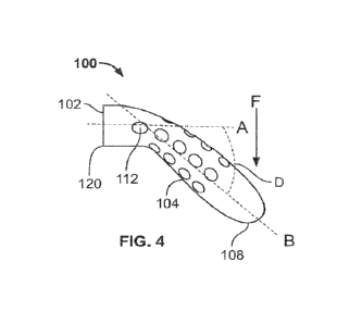
[00012] Fig. 4 is side view of the proximal insertion end portion of the
urinary
catheter of Fig. 2, shown with a force being applied to the proximal insertion
end
portion;
[00013] Fig. 5 is a partial side elevational view of another
embodiment of a
urinary catheter in accordance with the present disclosure;
[00014] Fig. 6 is a partial top view the of the urinary catheter of Fig. 5;
[00015] Fig. 7 is perspective view of the proximal insertion
end portion of the
urinary catheter of Fig. 5;
[00016] Fig. 8 is a partial cross-sectional view the of the
proximal end portion
of the urinary catheter of Fig. 5;
-2-
CA 03215017 2023- 10- 10
WO 2022/221509
PCT/US2022/024778
[00017] Fig. 9 is side view of the proximal insertion end
portion of the urinary
catheter of Fig. 5, shown with a force being applied to the proximal insertion
end
portion;
[00018] Fig. 10 is a partial side elevational view of another
embodiment of a
urinary catheter in accordance with the present disclosure;
[00019] Fig. 11 is perspective view of the proximal insertion
end portion of the
urinary catheter of Fig. 10;
[00020] Fig. 12 is side view of the proximal insertion end
portion of the urinary
catheter of Fig. 10, shown with a force being applied to the proximal
insertion end
portion;
[00021] Fig. 13 is a partial side elevational view of another
embodiment of a
urinary catheter in accordance with the present disclosure;
[00022] Fig. 14 is perspective view of the proximal insertion
end portion of the
urinary catheter of Fig. 13;
[00023] Fig. 15 is side view of the proximal insertion end portion of the
urinary
catheter of Fig. 13, shown with a force being applied to the proximal
insertion end
portion;
[00024] Fig. 16 is a partial side elevational view of another
embodiment of a
urinary catheter in accordance with the present disclosure;
[00025] Fig. 17 is perspective view of the proximal insertion end portion
of the
urinary catheter of Fig. 16; and
[00026] Fig. 18 is side view of the proximal insertion end
portion of the urinary
catheter of Fig. 16, shown with a force being applied to the proximal
insertion end
portion.
Detailed Description of the Embodiments
[00027] The present disclosure is directed to intermittent
urinary catheters
having flexible proximal insertion tips, wherein the drainage holes of the
urinary
catheter are positioned relatively close to the proximal terminal end of the
catheter
shaft and impart a selected or desired flexibility to the proximal insertion
tip of the
catheter shaft.
[00028] Turning now to Figs. 2-4, there is shown one
embodiment of a urinary
catheter 100 of the present disclosure. The urinary catheter 100 includes a
catheter shaft 102 having a proximal insertion end portion 104. Similar to
Fig. 1A,
the urinary catheter 100 also may include a distal end portion (not shown). In
this
-3-
CA 03215017 2023- 10- 10
WO 2022/221509
PCT/US2022/024778
embodiment and the other embodiments disclosed herein, the distal end portion
includes a drainage opening and, optionally, may include a drainage member
(not
shown) or be connected to a collection bag (not shown). Furthermore, the
urinary
catheter 100 includes a drainage lumen 106 (Fig. 3) that is in communication
with
the distal end drainage opening of the catheter shaft.
[00029] The proximal insertion end portion 104 includes a
terminal proximal
end 108. In this embodiment and the other embodiments disclosed herein, the
terminal proximal end 108 may be a closed end or an open end. When the
terminal end 108 is an open end, the terminal end includes an opening in
communication with drainage lumen 106. The proximal insertion end portion 104
also includes drainage hole region 110 (Fig. 2) located distally of the
proximal
terminal end 108. The drainage hole region 110 includes a plurality of
drainage
holes 112 extending through the proximal insertion end portion 104 and in
communication with the drainage lumen 106 (Fig. 3). Referring to Fig. 3, the
urinary catheter shaft 102 includes a sidewall 114 having an outer surface 116
and an inner surface 118. The drainage holes 112 extend through the sidewall
114 from the outer surface 116 to the inner surface 118. The outer surface 116
of
this embodiment, and in the other embodiments, may have a hydrophilic coating
disposed thereon. Turning back to Fig. 2, the drainage hole region 110 extends
along the catheter shaft 102 from the proximal most drainage hole 112a to the
distal most drainage hole 112b. Furthermore, in this and other embodiments,
the
drainage hole region may be located between about 2 mm and about 30 mm, or
preferably between about 5 mm and about 15 mm from the proximal terminal end
108.
[00030] The drainage holes 112 of this embodiment and other embodiments
disclosed herein may be formed in any suitable manner, including but not
limited
to, mechanical punching, thermal forming, ultrasonic cutting, laser cutting,
etc.
The drainage holes 112 in this embodiment and other embodiments disclosed
herein are in a patterned that imparts a selected or desired flexibility to
the
proximal insertion end portion 104, which allows the catheter to easily
navigate
the urethra.
[00031] In the illustrated embodiment, the drainage holes 112
are arranged in
a plurality of adjacent columns C and adjacent rows R. Each column C has an
axis parallel to the longitudinal axis A of the catheter shaft 102 and each
row R
-4-
CA 03215017 2023- 10- 10
WO 2022/221509
PCT/US2022/024778
extends circumferentially about the longitudinal axis A of the catheter shaft
102.
In the illustrated embodiment, the rows R and columns C are in a generally
uniform pattern. In alternative embodiments, the rows R and columns C may be
offset or in a variable pattern. The distance between adjacent rows and
adjacent
columns may be the same or may vary. Additionally, in the illustrated
embodiment, each of the drainage holes 112 has generally the same size and
shape. For instances, the drainage holes 112 have a generally round shape.
However, in other embodiments, the drainage holes may have other shapes, such
as oval, oblong, polygonal or irregular. In one embodiment, the drainage holes
112 may have an opening between about 0.4 mm and about 2 mm and preferably
about 0.72 mm and about 1.5 mm in their widest dimension, which may be a
diameter when the drainage hole is generally round. For example, the opening
be
about 1.2 mm wide. In alternative embodiments, the drainage holes 112 may
have various sizes and shapes relative to one another.
[00032] Referring to Fig. 4, the drainage holes 112 are sized, shaped, and
patterned to impart a selected or desired flexibility to the proximal
insertion end
portion 104. For example, the flexibility of the drainage hole region 110 may
be
between 10% and 70% more flexible, preferably 30% and 50% more flexible, than
the flexibility of a portion 120 of the catheter shaft 102 distal of the
drainage hole
region, as measured by an end loaded cantilever deflection test.
Alternatively, or
in addition to, when a force F of about 1.1 N is applied to the terminal end
108 of
the catheter shaft while a portion distal of the proximal insertion end 104 is
held in
a liner configuration, the proximal insertion end 104 bends such that the axis
B of
the proximal insertion end extends about 30 to 50 degrees D relative to the
longitudinal axis A of the catheter shaft 102. In one alternative, when 0.7 to
1.1 N
of force is applied to the terminal proximal end in a direction perpendicular
to the
longitudinal axis of the catheter shaft, the drainage hole region bends such
that
the longitudinal axis of the drainage hole region is about 30 to 50 degrees,
or
about 40 degrees relative to the longitudinal axis of the catheter shaft.
[00033] In use, proximal insertion end portion 104 is inserted into a
urethra.
As the proximal insertion end portion 104 is advanced through the urethra, the
proximal insertion end portion bends or flexes to assist in such advancement.
The
proximal insertion end portion is advanced until the drainage holes 112 enter
the
bladder. Because the drainage holes 112 are relatively close to the proximal
-5-
CA 03215017 2023- 10- 10
WO 2022/221509
PCT/US2022/024778
terminal end 108 of the catheter shaft 102, only a relatively short length of
the
catheter shaft 102 is required to be inserted into the bladder. The urine is
received into the drainage holes 112, flows through the drainage lumen 106 and
out of the drainage opening (not shown) in the distal end portion of the
catheter
shaft.
[00034] Figs. 5-9 illustrate another embodiment of a urinary
catheter 200 of
the present disclosure. The urinary catheter 200 includes a catheter shaft 202
having a proximal insertion end portion 204. Furthermore, the urinary catheter
200 includes a drainage lumen 206 (Fig. 8) that is in communication with the
distal
end drainage opening (not shown) of the catheter shaft.
[00035] The proximal insertion end portion 204 includes a
terminal proximal
end 208, which may be a closed end or an open end, as described above. The
proximal insertion end portion 204 also includes drainage hole region 210
(Figs. 5
and 6) located distally of the proximal terminal end 208. The drainage hole
region
210 includes a plurality of drainage holes 212 extending through the proximal
insertion end portion 204 and in communication with the drainage lumen 206
(Fig.
8). The drainage hole region 210 extends along the catheter shaft 202 from the
proximal most drainage hole 212a to the distal most drainage hole 212b.
[00036] The drainage holes 212 are in a patterned that imparts
a selected or
desired flexibility to the proximal insertion end portion 204. In the
illustrated
embodiment, the drainage holes 212 are in rows R that extend about the
longitudinal axis A of the catheter shaft 202. At least some rows Fi1_R5 of
drainage
holes 212 have a lesser amount of drainage holes 212 than an immediately
adjacent row of drainage holes. In the illustrated embodiment, the rows have
less
drainage holes 212 than immediate adjacent proximal rows. In other words,
moving distally along the catheter shaft, at least some rows R1-R5 have a
decreased number of drainage holes relative to proximal rows. In the
illustrated
embodiment, each row Ri-R5 has less drainage holes than its immediately
adjacent proximal row. In an alternative embodiment, at least some rows Ri-R5
may have an increased number of drainage holes relative to adjacent distal
rows.
In the illustrated embodiment, the drainage holes 212 have a generally round
shape. However, in other embodiments, the drainage holes may have other
shapes, such as oval, oblong, or polygonal. The drainage holes 212 may have
-6-
CA 03215017 2023- 10- 10
WO 2022/221509
PCT/US2022/024778
any of the sized described above. In alternative embodiments, the drainage
holes
212 may have various sizes and shapes relative to one another.
[00037] Referring to Fig. 9, the drainage holes 212 are sized,
shaped and
pattern to impart a selected or desired flexibility to the proximal insertion
end
portion 204. In illustrated embodiment, the rows increasing in the amount of
drainage holes toward the proximal terminal end 208 may result in variable
flexibility along the proximal insertion end portion 204. For example, the
proximal
segment of the drainage hole region 210, that includes relatively more
drainage
holes, may have greater flexibility than the distal segment of the drainage
hole
region 210. In other words, drainage hole region 210 may transition in
stiffness
from a stiffer distal end segment to more flexible proximal one.
[00038] In one embodiment, flexibility of at least one segment
of the drainage
hole region 210 of the catheter shaft may be between 10% and 70% and
preferably 30% and 50% more flexible than the flexibility of a portion 220 of
the
catheter shaft 202 distal of the drainage hole region, as measured by an end
loaded cantilever deflection test. Alternatively, or in addition to, when a
force F of
about 1.1 N is applied to the terminal end 208 of the catheter shaft 202 while
a
portion distal of the proximal insertion end 204 is held in a liner
configuration, the
drainage hole region 210 of the proximal insertion end may bend in an arc or
curvature G that decreases in radius of curvature from the distal end of the
drainage hole region 210 to the proximal end of said region. In other words,
the
radius of curvature is smaller at the proximal end than at the distal end.
[00039] Figs. 10-12 illustrate another embodiment of a urinary
catheter 300 of
the present disclosure. The urinary catheter 300 includes a catheter shaft 302
having a proximal insertion end portion 304. Furthermore, similar to the
previous
embodiments, the urinary catheter 300 includes a drainage lumen (not shown)
that is in communication with the distal end drainage opening (not shown) of
the
catheter shaft.
[00040] The proximal insertion end portion 304 includes a
terminal proximal
end 308, which may be a closed end or an open end, as described above. The
proximal insertion end portion 304 also includes drainage hole region 310
(Fig.
10) located distally of the proximal terminal end 308. The drainage hole
region
310 includes a plurality of drainage holes 312 extending through the proximal
insertion end portion 304 and in communication with the drainage lumen (not
-7-
CA 03215017 2023- 10- 10
WO 2022/221509
PCT/US2022/024778
shown). The drainage hole region 310 extends along the catheter shaft 302 from
the proximal most drainage hole 312a to the distal most drainage hole 312b.
[00041] The drainage holes 312 are in a patterned that imparts
a selected or
desired flexibility to the proximal insertion end portion 304. In the
illustrated
embodiment, the drainage holes 312 are in rows R, wherein at least some rows
R1_R5 of drainage holes have smaller holes than proximal rows of drainage
holes.
In the illustrated embodiment, the rows have smaller drainage holes than
immediate adjacent proximal rows. In other words, moving distally along the
catheter shaft, at least some rows R1-R5 have drainage holes of decreased size
relative to an adjacent row. In the illustrated embodiment, each row Ri-R5 has
drainage holes of a smaller size than the immediately adjacent proximal rows.
In
the illustrated embodiment, the drainage holes 312 have a generally round
shape.
However, in other embodiments, the drainage holes may have other shapes, such
as oval, oblong, or polygonal. In one embodiment, the drainage holes 312 may
have an opening between about 0.4 mm and about 2 mm, preferably about 0.73
mm and about 1.2 mm in their widest dimension, which may be a diameter when
the drainage hole is generally round. Furthermore, the size of the holes in
one
row may be between about 10% and 70% smaller, or preferably 20% and 40%
smaller, or preferably 20% than an adjacent row. Additionally, the size of the
holes may decrease a constant rate (percentage or width) in a series of rows.
The drainage holes 312 also may be arranged in uniform columns or in offset
columns. In an alternative embodiment, the rows R1-R5 may have drainage holes
of increased size relative to adjacent proximal rows.
[00042] Referring to Fig. 12, the drainage holes 312 are
sized, shaped, and
patterned to impart a selected or desired flexibility to the proximal
insertion end
portion 304. In illustrated embodiment, the increased size of drainage holes
toward the proximal terminal end 308 may result in variable flexibility along
the
proximal insertion end portion 304. For example, the proximal segment of the
drainage hole region 310, which includes relatively larger drainage holes, may
have more flexibility than the distal segment of the drainage hole region. In
one
embodiment, flexibility of at least one segment of the drainage hole region
310
may be between 10% and 70%, preferably 30% and 50% more flexible than the
flexibility of a portion 320 of the catheter shaft 302 distal of the drainage
hole
region, as measured by an end loaded cantilever deflection test.
Alternatively, or
-8-
CA 03215017 2023- 10- 10
WO 2022/221509
PCT/US2022/024778
in addition to, when a force F of about 1.1 N is applied to the terminal end
308 of
the catheter shaft 302 while a portion distal of the proximal insertion end
304 is
held in a liner configuration, the drainage hole region 310 of the proximal
insertion
end may bend in an arc or curvature G that decreases in radius of curvature
from
the distal end of the drainage hole region 310 to the proximal end of said
region.
In other words, the radius of curvature is smaller at the proximal end than at
the
distal end.
[00043] Figs. 13-15 illustrate another embodiment of a urinary
catheter 400 of
the present disclosure. The urinary catheter 400 includes a catheter shaft 402
having a proximal insertion end portion 404. Similar to that described above,
the
urinary catheter 400 includes a drainage lumen 406 (now shown) that is in
communication with the distal end drainage opening (not shown) of the catheter
shaft.
[00044] The proximal insertion end portion 404 includes a
terminal proximal
end 408, which may be a closed end or an open end. The proximal insertion end
portion 404 also includes drainage hole region 410 (Fig. 13) located distally
of the
proximal terminal end 408. The drainage hole region 410 includes a plurality
of
drainage holes 412 extending through the proximal insertion end portion 404
and
in communication with the drainage lumen (not shown). The drainage hole region
410 extends along the catheter shaft 402 from the proximal most drainage hole
412a to the distal most drainage hole 412b.
[00045] The drainage holes 412 are in a patterned that imparts
a selected or
desired flexibility to the proximal insertion end portion 404. In the
illustrated
embodiment, the drainage holes 412 are elongated slots or slits having an
elongated arc or axis H that extends partially along the outer circumference
of the
catheter shaft 402. The drainage holes 412 may have a length L of 2 mm to 3
mm, preferably 2.6 mm and a width W of 0.1 to 0.3 mm and preferably 0.2 mm.
Additionally, the slits may be aligned in offset columns C. The columns C have
an
axis that is parallel with the axis A of the catheter shaft 402.
[00046] Referring to Fig. 15, the drainage holes 412 are sized, shaped, and
patterned to impart a selected or desired flexibility to the proximal
insertion end
portion 404. For example, the flexibility of the drainage hole region 410 may
be
between 10% and 70% preferably 50 % and 70 c/o more flexible than the
flexibility
of a portion 420 of the catheter shaft 402 distal of the drainage hole region,
as
-9-
CA 03215017 2023- 10- 10
WO 2022/221509
PCT/US2022/024778
measured by an end loaded cantilever deflection test. Alternatively, or in
addition
to, when a force F of about 0.7 N is applied to the terminal end 408 of the
catheter
shaft while a portion distal of the proximal insertion end 404 is held in a
liner
configuration, the proximal insertion end 404 bends such that the axis B of
the
proximal insertion end extends about 40 to 60 degrees or preferably 50 degrees
D
relative to the longitudinal axis A of the catheter shaft 402.
[00047] Figs. 16-18 illustrate another embodiment of a urinary
catheter 500 of
the present disclosure. The urinary catheter 500 includes a catheter shaft 502
having a proximal insertion end portion 504. Similar to that described above,
the
urinary catheter 500 includes a drainage lumen 506 (not shown) that is in
communication with the distal end drainage opening (not shown) of the catheter
shaft.
[00048] The proximal insertion end portion 504 includes a
terminal proximal
end 508, which may be a closed end or an open end. The proximal insertion end
portion 504 also includes drainage hole region 510 (Fig.16) located distally
of the
proximal terminal end 508. The drainage hole region 510 includes a plurality
of
drainage holes 512 extending through the proximal insertion end portion 504
and
in communication with the drainage lumen 506 (not shown). The drainage hole
region 510 extends along the catheter shaft 502 from the proximal most
drainage
hole 512a to the distal most drainage hole 512b.
[00049] The drainage holes 512 are in a patterned that imparts
a selected or
desired flexibility to the proximal insertion end portion 504. In the
illustrated
embodiment, the drainage holes 512 are slots having a size and shape similar
to
that described above with respect to Figs. 13-15. In this embodiment, the
slots
are patterned in a helical pattern or configuration about axis A of the
catheter shaft
502.
[00050] Referring to Fig. 18, the drainage holes 512 are
sized, shaped, and
patterned to impart a selected or desired flexibility to the proximal
insertion end
portion 504. For example, the flexibility of the drainage hole region 510 may
be
between 30% and 70%, preferably 40 % and 60 % more flexible than the
flexibility
of a portion 520 of the catheter shaft 502 distal of the drainage hole region,
as
determined by an end loaded cantilever deflection test. Alternatively, or in
addition to, when a force F of about 0.9 N is applied to the terminal end 508
of the
catheter shaft while a portion distal of the proximal insertion end 504 is
held in a
-10-
CA 03215017 2023- 10- 10
WO 2022/221509
PCT/US2022/024778
liner configuration, the proximal insertion end 504 bends such that the axis B
of
the proximal insertion end extends about 40 to 60 degrees, preferably 50
degrees
D relative to the longitudinal axis A of the catheter shaft 502.
[00051] It should be understood that various changes and
modifications to the
presently preferred embodiments described herein will be apparent to those
skilled in the art. Such changes and modification can be made without
departing
from the spirit and scope of the invention disclosed herein.
-11 -
CA 03215017 2023- 10- 10